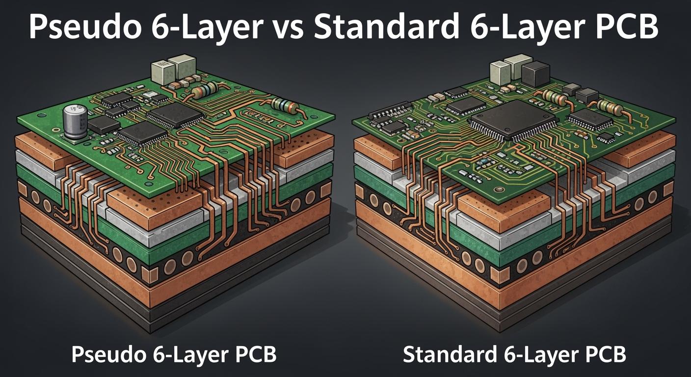
You may see the words pseudo 6-layer and standard 6-layer PCB when you make electronics. A standard 6-layer PCB has six copper layers. A pseudo 6-layer uses a stackup that acts like six layers. It may have different core setups inside. Knowing the PCB layer count and how the stackup works helps you pick better options for your projects.
Key Takeaways
Learn how standard and pseudo 6-layer PCBs are different. This helps you pick the best one for your project.
Choose a standard 6-layer PCB if you want to save money. It gives good signal quality and is easier to make.
Pick a pseudo 6-layer PCB for better results with fast signals. It also helps control crosstalk more.
Think about the stackup arrangement before you decide. It changes signal strength, noise, and how well the PCB works.
Talk to your manufacturer about stackup options. This makes sure your PCB works well and arrives on time.
PCB Layer Count and Stackups
Standard 6-Layer PCB Structure
Many electronics use a 6-layer pcb. The pcb layer count shows how many copper layers are inside. Each layer does something important. Some layers move signals. Other layers are ground or power planes. The way you put these layers together is called the stackup.
Here is a usual stackup for a standard 6-layer pcb:
Layer Number | Layer Type |
|---|---|
1 | Signal Layer |
2 | Ground Plane |
3 | Signal Layer |
4 | Power Plane |
5 | Ground Plane |
6 | Signal Layer |
This stackup helps keep signals strong. Signal layers go next to ground or power planes. This setup lowers noise and crosstalk. It also helps power move better. The pcb layer count and the order of layers both help the board work well.
Tip: Using this stackup means less electromagnetic interference (EMI) and better signals.
Pseudo 6-Layer Stackup Explained
A pseudo 6-layer stackup looks like it has six layers, but the inside is built differently. You use three cores in this design. The middle core often has its copper taken away. This makes more space between layers. It helps lower crosstalk between signals.
You use prepreg instead of a thin core for the outside layers. Prepreg is a special glue that holds layers together. Using prepreg in the center makes the board thinner and easier to bend. This changes how the pcb layer count works inside. The stackup acts like a 6-layer pcb, but the build is not the same as a standard pcb stackup.
Pseudo 6-layer stackups have three cores.
The middle core has copper removed to make more space.
Prepreg takes the place of thin core material for the outside layers.
The center uses prepreg layers for better control.
This design helps control crosstalk and makes the board less likely to change during making.
Key Differences in PCB Construction
It is important to know how each stackup affects your project. The standard 6-layer pcb uses thin prepreg in the center. This makes layers stick together well, but it can change if the prepreg thickness is different. Small changes can hurt signals.
The pseudo 6-layer stackup uses more cores and more prepreg in the center. This gives more space between layers. It helps lower crosstalk and makes the board stronger. You can use a pseudo 8-layer stackup to fix crosstalk problems in a standard 6-layer build. Changing the stackup helps the pcb layer count work better and gives better results for fast signals.
Standard 6-layer pcb: Thin center prepreg, strong but can change easily.
Pseudo 6-layer: More cores, more prepreg, bigger space between layers, less crosstalk.
Pseudo 8-layer stackup: Used to fix crosstalk in standard 6-layer designs.
When you pick a stackup, think about your pcb layer count, the number of layers, and how you arrange them. This choice changes signal strength, noise, and how good your pcb is.
Performance and Application
Signal Integrity and EMI in 6-Layer PCBs
When you design a pcb, you must think about signal integrity. Signal integrity means signals stay strong and clear as they move. A good stackup helps keep signal integrity high. In a standard 6-layer pcb, signal layers are next to ground or power planes. This setup lowers noise and keeps signals from mixing. It also helps stop electromagnetic interference, called EMI, because the layers protect the signals.
A pseudo 6-layer stackup has more space between layers. This extra space helps lower crosstalk. Crosstalk is when signals from one trace jump to another. You get better control over signal integrity, especially with fast signals. If you want less EMI, you should look at how you arrange the stackup and pcb layer count. Picking the right layer count helps you avoid noise and keeps signals clean.
Tip: Put signal layers close to ground or power planes for best performance and lowest EMI.
Reliability and Durability Factors
You want your pcb to last long and work well in hard places. Reliability means your board keeps working without problems. Durability means it can handle stress, heat, and bending. How you build your stackup changes how strong your board is.
A standard 6-layer pcb uses thin prepreg in the center. This makes the board strong, but small changes in prepreg thickness can hurt how it works. A pseudo 6-layer stackup uses more cores and more prepreg in the center. This design gives you a board that is less likely to bend or change shape. You get better reliability because the layers stay in place. The extra space between layers also helps protect your signals.
If you work in automotive, aerospace, or healthcare, you need high reliability. These fields use 6-layer pcbs because they work well and can handle complex designs. You should always check your stackup and pcb layer count to make sure your board will last.
Use Cases for Each PCB Type
You can find both standard and pseudo 6-layer pcbs in many industries. Each type fits different needs. Here are some examples:
Industry | Reasons for Choosing 6-Layer PCBs |
|---|---|
Wearable Devices | You need small and light boards for gadgets. |
Communication Equipment | You want strong construction and good electrical properties. |
Military | You look for better durability and performance in complex systems. |
Healthcare Equipment | You need better performance and reliability in medical devices. |
You see standard 6-layer pcbs in cars, planes, telecom, and electronics. These industries pick them because new devices need more complex and small designs. You also get better performance, strong signal integrity, and less EMI. The stackup and layer count help you meet these needs.
A pseudo 6-layer stackup is good when you want less crosstalk or a board that does not bend easily. You might use this type if you design fast circuits or need more control over your signals.
Pick a standard 6-layer pcb for lower cost and simple stackup.
Pick a pseudo 6-layer when you need better performance for fast signals or more reliability.
Note: As devices get more complex, you need to watch stackup, pcb layer count, and performance needs.
Cost and Manufacturing
Cost Comparison: Pseudo vs Standard
You want to know how much each pcb type costs. The stackup you choose changes the price. A standard 6-layer pcb uses a simple stackup. You pay less because the process uses fewer steps. The materials are common, and the layers fit together easily. You save money when you pick this option for basic designs.
A pseudo 6-layer stackup costs more. You need extra cores and more prepreg. The process takes more time. The stackup needs careful control to keep the layers spaced right. You pay more for better signal control and less crosstalk. If your project needs high speed or strong reliability, you may find the extra cost worth it.
PCB Type | Material Cost | Labor Cost | Total Cost |
|---|---|---|---|
Standard 6-layer | Low | Low | Lower |
Pseudo 6-layer | Medium | Medium | Higher |
If you want to save money, pick a standard stackup. If you need better performance, choose a pseudo 6-layer stackup.
Manufacturing Complexity and Lead Time
You must think about how hard it is to make each pcb. The stackup design changes the steps in manufacturing. A standard 6-layer pcb uses a simple stackup. The layers go together fast. You get a short lead time. The process is easy to control.
A pseudo 6-layer stackup adds more steps. You need to align extra cores and prepreg. The layers must stay spaced right. The process takes longer. You wait more for your finished pcb. The stackup design makes the job harder for workers and machines.
Manufacturing complexity can cause problems. You see more defects when the stackup is complex. Here are some reasons:
Technical faults can happen during layer alignment.
Polluted work environments may cause surface defects.
Device anomalies can affect the stackup process.
Manual mishandling can damage layers.
These problems can lower the reliability of your pcb. You must check the stackup and pcb layer count before you order. If you want fast delivery and fewer defects, pick a standard stackup. If you need special performance, accept a longer lead time for a pseudo 6-layer stackup.
Tip: Always talk to your manufacturer about stackup choices and how they affect layers, cost, and delivery time.
Pros and Cons Table
When you choose between a standard 6-layer and a pseudo 6-layer pcb, you need to look at the good and bad points of each type. This table helps you see the main differences. You can use it to decide which one fits your project best.
Feature | Standard 6-Layer PCB | Pseudo 6-Layer PCB |
|---|---|---|
Cost | Lower | Higher |
Signal Integrity | Good for most uses | Better for high-speed signals |
Crosstalk Control | Basic | Improved |
Manufacturing Time | Short | Longer |
Reliability | Good | Very good |
Stackup Complexity | Simple | More complex |
Flexibility | Less flexible | More flexible |
Best For | Everyday electronics | High-speed or tough projects |
Tip: Use this table when you plan your next design. It helps you match the right board to your needs.
Key Points to Remember
You get lower cost and faster delivery with a standard 6-layer board.
You get better signal control and less crosstalk with a pseudo 6-layer board.
If you work with fast signals or need extra strength, pick the pseudo type.
For simple projects, the standard type works well.
You should always talk to your manufacturer before you order. Ask about the stackup and how it fits your project. The right choice gives you a strong and reliable pcb.
Choosing the Right PCB Type
Decision Factors for Engineers
You have many choices when picking a pcb for your project. The stackup you choose changes how well your design works. First, look at how many layers you need. More layers help with hard circuits and better signals. If you want strong performance, check how the stackup stops crosstalk and helps fast signals. Think about where your pcb will be used. If your board faces heat, shaking, or bending, pick a stackup that makes it stronger. Reliability is very important in these cases. You also need to think about cost and how fast you need your boards. A simple stackup with fewer layers costs less and comes faster. For fast circuits, use a signal integrity plan that fits your stackup.
Tip: Always match your stackup to what your pcb needs and where it will work.
Application Scenarios
You can find different stackup choices in many real-life uses. Each pcb type fits a special job. The table below shows how engineers use different stackups and layers for the best results.
PCB Type | Application Type | Key Features |
|---|---|---|
Flexible PCBs | High-Frequency Applications | Stable dielectric constants, excellent signal integrity for 5G millimeter-wave. |
Rigid-Flex Boards | High-Density, Ruggedized | Combines flexible and rigid designs, ideal for complex applications requiring both static and dynamic connections. |
Rigid PCBs | Cost-sensitive, Standard Mounting | Effective for applications with no movement needed, meeting functional requirements while controlling costs. |
You should use multilayer pcbs when your design needs high performance and strong reliability. For high-frequency or high-density projects, more layers in the stackup give you better signals and make the board work better. If you want to save money and do not need extra features, a simple rigid pcb with a basic stackup is a good choice.
Remember: Picking the right stackup and layer count helps you reach your goals and keeps your pcb working well.
You have learned how pseudo 6-layer and standard 6-layer pcb designs are different. Use the standard type if your project is simple and you want to save money. Choose the pseudo type if your project needs to handle fast signals or tough jobs. Think about what your project needs before you pick one:
Decide what you want for electricity, heat, and strength.
Choose materials that help your board work well.
Plan your stackup to keep signals clear and your board strong.
Good planning helps your design work its best.
FAQ
What is the main benefit of a pseudo 6-layer PCB?
You get better control over crosstalk and signal integrity. The extra space between layers helps your high-speed signals stay clean. This makes your board work better in demanding applications.
Can you use a standard 6-layer PCB for high-speed designs?
You can use a standard 6-layer PCB for many projects. For very fast signals, you may see more crosstalk or noise. If you need top performance, consider a pseudo 6-layer stackup.
Does a pseudo 6-layer PCB cost more to make?
Yes, you pay more for a pseudo 6-layer PCB. The extra cores and careful layer spacing increase both material and labor costs. You should choose this type when your project needs better performance.
How do you choose between standard and pseudo 6-layer PCBs?
Check your signal speed and reliability needs.
Look at your budget and delivery time.
Ask your manufacturer for advice.
You should match the stackup to your project goals.
Are pseudo 6-layer PCBs harder to manufacture?
You may find pseudo 6-layer PCBs more complex to build. The process needs careful alignment and more steps. This can lead to longer lead times and a higher chance of defects if not managed well.