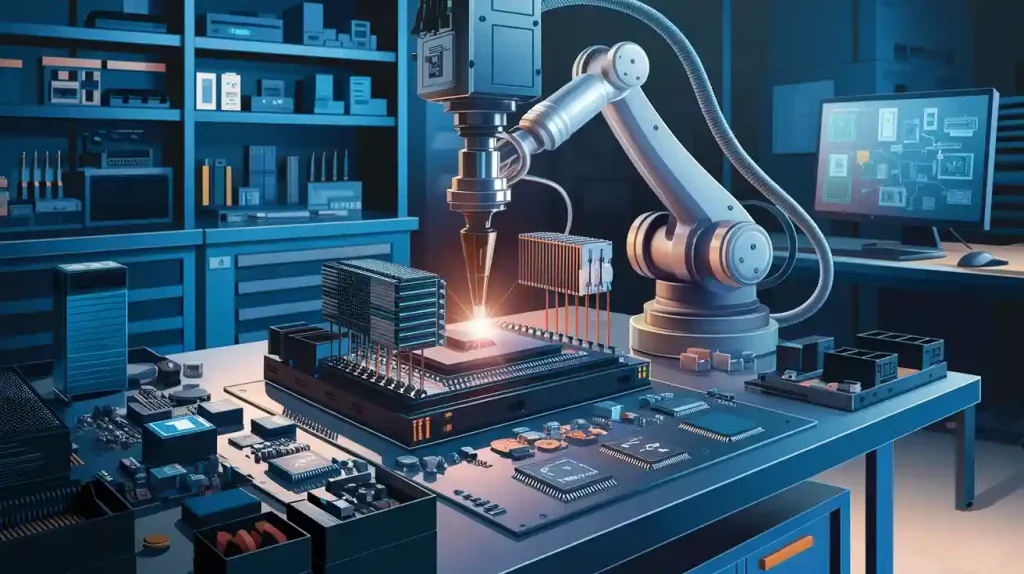
PCB application is crucial for enhancing the performance and longevity of EV DC-DC converters. Engineers develop specialized printed circuit boards to integrate power and control circuits effectively. This PCB application enables the system to deliver higher power density within a compact space while improving EMC performance. As a result, battery electric vehicles can better manage power, reduce energy waste, and improve heat dissipation. The table below illustrates how embedded PCB application technology contributes to power, EMC, and reliability in electric vehicle power electronics.
Aspect | Contribution to High Power Density and Reliability |
|---|---|
Miniaturization | Incorporating components within the PCB application saves space, making the system smaller and capable of handling more power. |
Heat Dissipation | Lead frames distribute heat efficiently, and copper-filled micro vias reduce thermal resistance, strengthening the system. |
Electrical Performance | Low bond wire resistance and minimal parasitic inductance in the PCB application enable faster switching with less energy loss. |
Reliability | Embedded PCB application technology enhances system reliability, with power cycling tests demonstrating durability beyond 700,000 cycles. |
System Integration | Combining power and control circuits on a single PCB application simplifies design, reduces size and cost, and boosts EMC performance. |
High Current Capability | Embedded shunts with improved thermal management in the PCB application allow for more accurate high current measurements. |
Cost Reduction | Reducing the need for connectors, cables, cooling, and smaller part sizes through PCB application lowers overall system costs. |
Applicability | This PCB application is suitable for both low voltage high current and high voltage wide band gap semiconductor implementations. |
Key Takeaways
Smart PCB design helps EV DC-DC converters work better. It makes them smaller and lighter. It also makes them more powerful. Using thick copper layers spreads heat well. Thermal vias help keep converters cool. This makes them more reliable. Good PCB layout lowers electrical noise. Good grounding helps too. This makes the system stable and safe. Putting power and control circuits on one PCB saves space. It also lowers costs and boosts performance. Advanced features help even more. Bidirectional power flow and synchronous rectification save energy. They also make the system more efficient.
PCB Application in DC-DC Converters
Power Distribution and Signal Control
A printed circuit board is very important in dc-dc converters. It helps move power and control signals in a small space. Engineers design the pcb application to handle strong currents and sensitive signals together. This helps electric vehicles use power better and work well.
The pcb application sends power from the battery to things like lights, screens, and the motor. Careful design makes sure power parts get steady voltage and current. This keeps energy loss and voltage drops low. Signal lines on the pcb carry control messages between microcontrollers and power converters. This lets the system react quickly and control power well.
Some dc-dc converters, like ones with MPQ2967-AEC1 and MPQ86960-AEC1, show how putting power and control circuits on one pcb helps. These designs give steady power and good signals, even in tough car conditions. They also help advanced driver-assistance systems (ADAS) work better.
Tip: Engineers use multi-layer pcb designs to keep power and signal layers apart. This lowers interference and helps with electromagnetic compatibility (EMC).
Integration of Components
Putting transformers and power stages right on the pcb is a big step forward. This makes the converter smaller and easier to build. The pcb application helps make designs that fit in tight spaces and are not too heavy for electric cars.
The table below shows how different ways of putting parts together change power density, efficiency, and how easy they are to make:
Converter Stage / Design Approach | Key Integration Features | Power Density (W/in³) | Efficiency (%) | Manufacturing & Performance Benefits |
|---|---|---|---|---|
Single-phase CLLC (1PCLLC) with PCB-based integrated transformer | Integrated matrix transformer with controllable leakage inductance; reduced core loss; smaller footprint; SiC devices at 250 kHz switching | 250 | 98.4 | Reduced magnetic components; compact design; enhanced power density and efficiency |
1PCLLC with winding cancellation technique | Winding cancellation to reduce common mode noise by 17 dB; EMI mitigation | 420 | 98.5 | Improved EMI performance; better parasitic management; enhanced converter reliability |
Three-phase CLLC (3PCLLC) resonant converter | Integrated three-phase transformer combining multiple inductors and transformers; symmetrical resonant tank; soft switching; variable DC-link voltage | 330 | 98.7 | Simplified magnetic components; scalable design; improved thermal and electrical performance |
Scalable matrix integrated transformer for multi-phase CLLC | Integration of multiple perfectly coupled transformers (PCTs) with built-in leakage inductance; standardized or customized cores for better flux distribution and lower core loss | 500 | 98.8 | High power density; peak efficiency; scalable for higher power applications; streamlined manufacturing |

A transformer-in-package dc-dc converter uses special packaging to put the transformer and connections inside. This means fewer parts and a smaller size. This design gets a high quality factor and coupling factor. It works better and can reach a peak power density of 50 mW/mm².
Real car examples show this works well. The Intelli-Phase solution uses the MPQ86940 and MPQ2977-AEC1 controller. It gives smart and strong power to high-tech computers in cars. The MPQ4326-AEC1 dc-dc converter also puts power management ICs on a small pcb. This helps it stay cool and work well, even when things get tough.
Note: Putting power semiconductors and transformers on the pcb makes power density higher. It also makes building easier, costs less, and makes the system more reliable.
Adding more parts to the printed circuit board changes how dc-dc converters help electric vehicles. With new pcb application methods, engineers make small, strong, and dependable power systems. These systems help new car technology work better.
PCB Materials and Construction
Heavy Copper and High-Current Traces
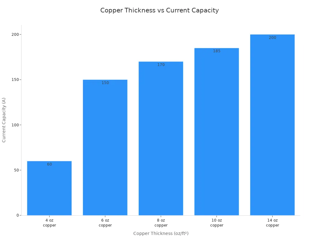
Engineers pick heavy copper layers for pcb construction in EV DC-DC converters. These thick copper traces are between 4 oz and 14 oz per square foot. They help the board carry high currents, sometimes up to 200 amps. Heavy copper acts like a heat sink and spreads heat well. This stops hotspots and keeps the board cooler by 20-30°C. It helps the system stay reliable in tough car conditions.
Manufacturers use selective plating to add more copper only where it is needed. This saves money and supports high-current paths. Wide traces and many vias help carry more current and spread heat. For example, a 10 oz copper trace can carry about 65 amps on a 0.25-inch width. This matches what modern power electronic substrates need.
Tip: Thick copper layers have lower resistance. This means less voltage drop and more power for the parts. It makes the pcb and power electronic substrates last longer and work better.
Copper Thickness (oz/ft²) | Current Capacity (A) | Key Benefit |
|---|---|---|
4 | 60 | Good for moderate loads |
6 | 150 | Excellent heat dissipation |
10 | 200 | Maximum reliability & power |
Multi-Layer and IMS Boards
Multi-layer pcb designs and insulated metal substrate (IMS) boards are important in EV DC-DC converters. Multi-layer boards have several layers stacked together. This keeps power and control circuits apart. It helps the board work better and lowers electromagnetic interference. IMS boards have a metal base that spreads heat fast. This makes them great for high-power uses.
Halogen-free, high CTI, and high RTI materials are used in these boards. Panasonic’s R-3566D is one example. These materials can handle high heat and voltage. They support new power electronic substrates like SiC and GaN devices. IMS boards can make parts 20-30°C cooler than normal boards. This makes parts last twice as long and makes the system more reliable.
Top-side cooling can lower thermal resistance by up to 35%.
IMS boards do not need big heat sinks, so they are smaller and lighter.
Better heat spreading and insulation stop failures from heat and shaking.
Using the right pcb materials and ways to build them gives high efficiency, strong heat spreading, and long-lasting reliability in EV power systems.
Layout and EMI Management

Trace Routing and Grounding
Engineers know layout is very important for dc-dc converters in cars. They use multilayer pcb designs with special ground and power layers. This helps stop emc problems and keeps signals clear. Putting signal layers next to ground layers makes loops smaller and lowers radiation. When ground and power layers are close, it helps with decoupling and boosts emc.
Some good ways to route traces and ground are:
Keep traces short and straight to stop antenna effects and emc issues.
Use stitching vias to link ground layers, which lowers impedance and helps return paths.
Put decoupling capacitors near IC power pins to keep voltage steady and cut noise.
Do not use right-angle bends in traces; 45-degree or curved bends are better for emc.
Good grounding, like star grounding, helps stop ground loops and noise. Keeping fast signals away from slow or analog signals stops interference. These steps help dc-dc converters pass tough emc rules for cars.
Good pcb layout and grounding not only lower emc but also make converters more reliable and work better.
Minimizing Parasitics
Parasitic inductance and capacitance can cause emc problems and lower efficiency in dc-dc converters. Engineers pick surface mount devices for capacitors and resistors to keep connections short and cut down parasitic effects. They use both film and ceramic capacitors to get low impedance at many frequencies, which helps emc.
To cut parasitics even more:
Engineers make solid, wide ground layers instead of thin traces.
They do not use long wires to chassis, which can make loops bigger and cause emc issues.
Damping resistors in capacitor groups stop resonance that can hurt emc.
Placing parts carefully and routing well helps lower both conducted and radiated emissions. For example, putting ground layers under signal traces cuts magnetic flux and emc. Keeping noisy switching parts away from sensitive circuits also lowers electromagnetic coupling.
Car dc-dc converters that use these layout ideas show better emc and meet standards like CISPR 25. These ways make sure power is steady and safe in tough car jobs.
Thermal Management in Electric Vehicle Converters

Heat Spreading and Vias
Engineers use smart ways to help heat leave electric vehicle DC-DC converters. Thick copper layers in the pcb move heat away from hot parts. The copper spreads heat across the board. Small metal-filled holes called thermal vias sit under very hot parts. These vias move heat between pcb layers. This stops hot spots and keeps the board at even temperatures.
Heat spreading planes connect to ground or power layers. These planes lower thermal resistance and help heat leave faster. Direct Bonded Copper (DBC) substrates use thick copper stuck to ceramic. This setup spreads heat fast and keeps the pcb strong, even when the car uses lots of power. DBC technology handles high current and helps the system stay strong under stress.
Engineers pick copper because it moves heat well. This keeps sensitive parts safe in high-power ev systems.
Integration of Heat Sinks
Adding heat sinks to the pcb design changes how power modules handle heat. When engineers put heat sinks on the board, they lower the hottest temperatures in the ev DC-DC converter. Without heat sinks, parts can get too hot and break. With heat sinks, the system stays cooler and safer.
This way, there is no need for extra pads, grease, or clamps. It also lets machines build the boards, which saves money and lowers mistakes. Using lighter pcb materials instead of heavy ones makes the car weigh less. Heat sinks on power semiconductors help heat leave and keep parts cool. This makes ev power electronics safer and more reliable.
A good thermal management plan in pcb design helps electric vehicles last longer. It stops overheating, supports high current, and keeps the system safe in hard conditions.
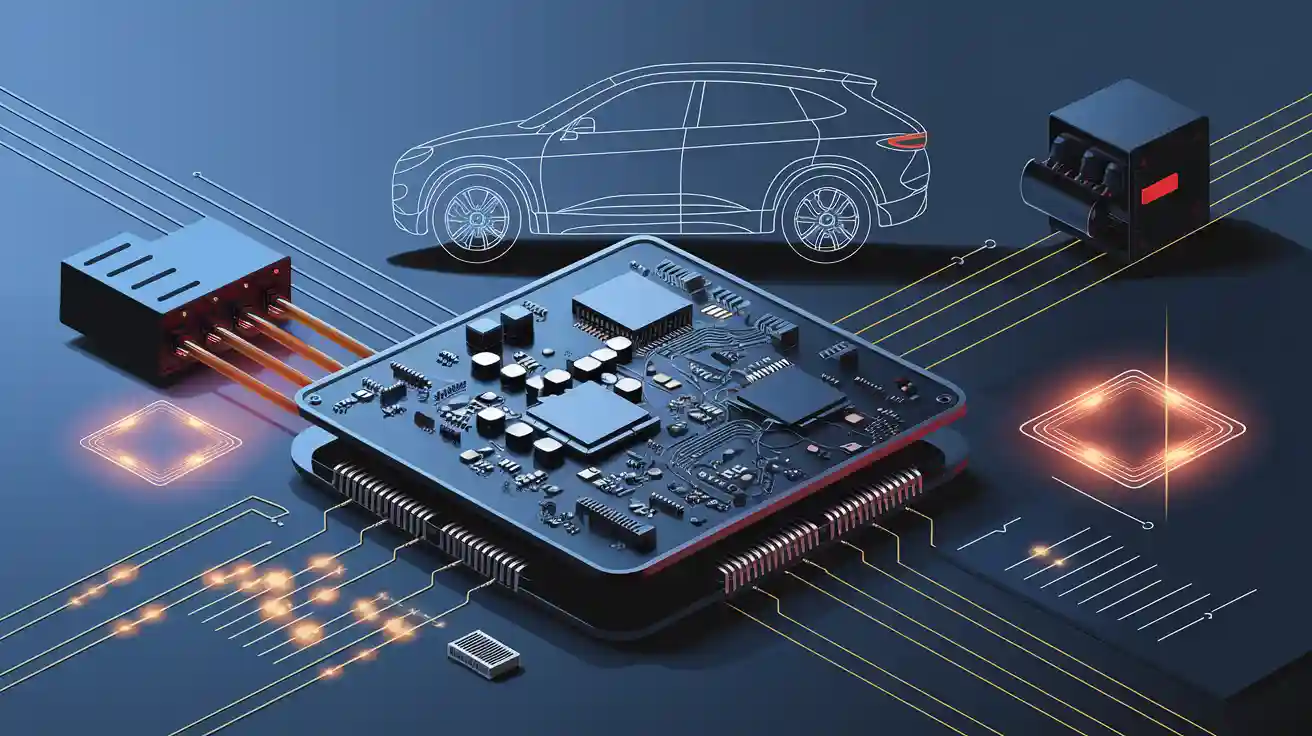
Integration and Miniaturization
Embedded Components
Engineers use miniaturization to help electric vehicles work better. They put power and control circuits together on one pcb. This makes the system small so it fits in tight spaces. There are many good things about this:
Putting both circuits on one pcb makes the converter smaller and lighter.
Higher switching speeds are possible, so smaller parts can be used. This makes the design lighter and smaller.
Smaller chokes with less unwanted capacitance help at high speeds. This also cuts down size and weight.
Fast microcontrollers with good PWM help new power designs and faster switching.
All these things make it easier to put the system together, lower weight, and make it stronger and cooler.
Miniaturization also helps battery electric vehicles by making power modules tougher and easier to cool. This is very important for long-lasting use.
Compact System Design
Small pcb designs in electric vehicles use new ways to build boards, like SMT and HDI. These ways let engineers make tight layouts that save space and weight. Using these methods, the pcb can be up to 30% smaller. Shorter signal paths help the board work better and cut down on noise.
Machines put tiny parts on the board very accurately. This saves money and lets more parts fit on the board.
Smaller boards use less material, which saves money and makes the car lighter.
Special materials like polyimide and LCP help the board handle heat and keep signals clear.
Flexible and rigid-flex pcbs can bend or fold, so they fit in small spaces in cars.
Miniaturized pcbs let engineers add more features to small boards. This gives more room for other systems, like ADAS and battery management. Small boards that spread heat well help batteries work better and save energy. These pcbs also help with things like self-driving by making data move faster and more reliably. Because of this, electric cars get lighter, smarter, and cheaper, with better range and reliability.
Advanced Features in DC-DC Converters
Bidirectional Power Flow
Today’s dc-dc converters in electric cars can move power both ways. Engineers use special pcb layouts to make this work. These designs use a CLLC resonant converter with a full-bridge setup. The converter sends energy from the battery to the grid or back again. This helps with things like vehicle-to-grid (V2G) and vehicle-to-building (V2B).
The resonant converter uses soft-switching, so it makes less heat and loses less energy.
Wide bandgap semiconductors like SiC and GaN switch faster and waste less power.
Real-time microcontrollers and gate drivers control which way the power goes.
The pcb has sensing and feedback circuits for better control.
Tests show these bidirectional dc-dc converters work well in real cars. They can change for different battery voltages and lose less energy when charging. Soft-switching also cuts down on electromagnetic interference, so the system is more reliable. These features help electric cars charge faster and send power back to the grid when needed.
Bidirectional power flow in dc-dc converters gives electric cars more options and helps with new energy uses.
Synchronous Rectification
Synchronous rectification is another important feature in new dc-dc converters. Instead of diodes, engineers use MOSFETs with low resistance. This lowers voltage drop and saves power. The pcb supports new MOSFET packages that carry more current and spread heat better.
Synchronous rectification uses control ICs to switch MOSFETs at the right time.
The pcb design lets the converter run at high frequencies, making it smaller and more efficient.
Better thermal management keeps the system cool and working well.
Tests show synchronous rectification makes converters more efficient and cooler. For example, smart control stops reverse conduction, which wastes energy. High-frequency operation also means the dc-dc converter can be smaller, saving space in electric cars.
Synchronous rectification, made possible by smart pcb design, helps dc-dc converters give more power with less waste.
PCB design helps EV DC-DC converters work better and last longer. It makes the system more reliable and boosts how well it performs. High power density lets cars be lighter and react faster. Fast response means the system can change power quickly. Bidirectional power flow lets energy move both ways, which helps save energy. The table below shows how these features help with emc and make the system work better:
PCB Design Aspect / Power Module Feature | Impact on EV DC-DC Converter Efficiency, Reliability, and Performance |
|---|---|
High power density modules | Smaller, lighter vehicles; improved range and packaging |
Fast transient response | Better system reliability; rapid power changes |
48V zonal architectures | Higher electrical efficiency; reduced losses |
Bidirectional power flow | Enhanced energy recovery; improved emc |
Modular, scalable design | Lower cost; easier maintenance |
High efficiency regulation | Less power loss; better thermal management |
Picking the right materials, good layout, and smart cooling are all important. Putting parts together in a smart way also helps power electronics work their best. The table below shows how each part helps:
Aspect | Contribution to EV Power Electronics Optimization |
|---|---|
Material Choice | Wide bandgap semiconductors and thermal interface materials improve heat dissipation and voltage handling |
Layout | Double-sided cooling and smart trace routing boost emc and reliability |
Thermal Management | Advanced cooling and heat sinks reduce hotspots and failure points |
Integration | Combining thermal and electrical features in one module increases efficiency and shortens supply chains |
Engineers can use these tips to make emc and reliability better:
Make high-frequency traces short and wide.
Keep noisy and sensitive signals apart.
Put decoupling capacitors close to power parts.
Use shielding and filters to stop emc problems.
Add heat sinks and thermal vias to cool things down.
Technical managers should use design tools that work together. They should test early with computer models and real hardware. This helps find emc problems before they become big issues. By using these ideas, teams can build strong and efficient EV DC-DC converters. These converters will meet tough emc rules and help electric cars work better in the future.
FAQ
What is the main benefit of using multi-layer PCBs in EV DC-DC converters?
Multi-layer PCBs let engineers keep power and control circuits apart. This makes less noise and helps the system work better. It also lets the converter fit into smaller spots in electric cars.
How do engineers manage heat in high-power DC-DC converters?
Engineers use thick copper, thermal vias, and heat sinks. These things help move heat away from hot parts. Good heat control keeps the system safe and helps it last longer.
Why is emc important in EV DC-DC converter design?
emc makes sure the converter does not make extra electrical noise. This helps the car’s electronics work without problems. Following emc rules is very important for safety and good performance.
Can PCB design affect the weight of an electric vehicle?
Yes. Small PCB layouts and built-in parts make power modules smaller and lighter. Lighter systems help electric cars go farther and use less energy.
What role do wide bandgap semiconductors play in PCB-based converters?
Wide bandgap semiconductors like SiC and GaN switch faster and handle more voltage. They let engineers make smaller, better converters that do not get as hot.