PCB application is crucial for fast charging electric systems. Engineers create specialized PCB designs to handle high heat and power levels. They incorporate materials like DOWSIL™ coatings and encapsulants to protect electrical components.
PCBs support capacitors, semiconductors, and magnetic devices, all essential for electric charging.
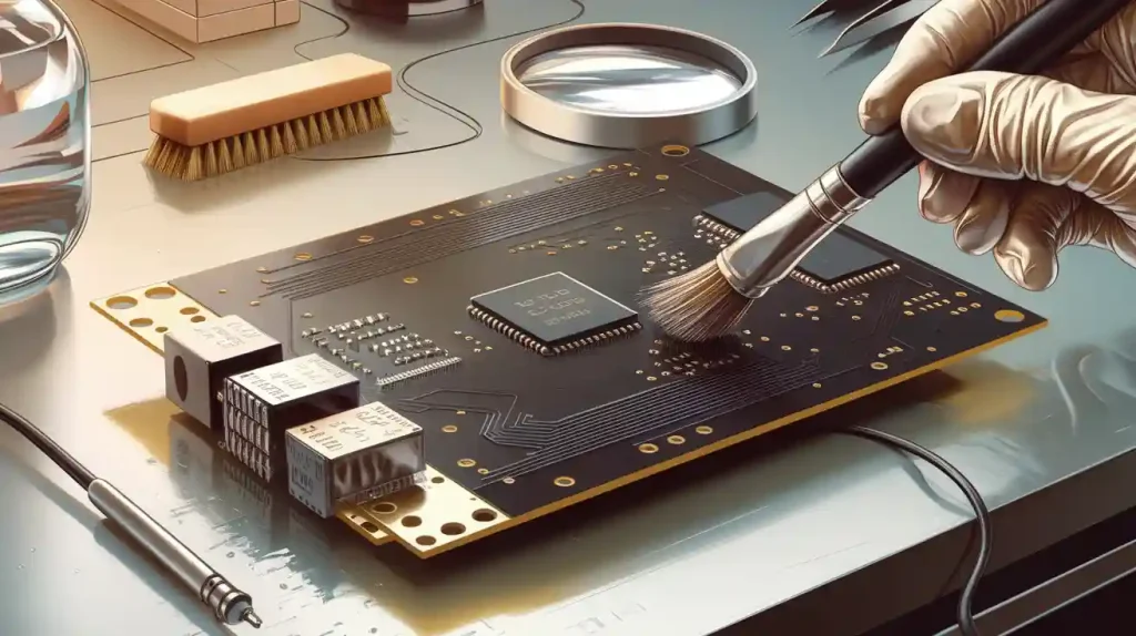
Effective thermal management and insulation are key to maintaining performance and preventing dirt and damage.
Proper system construction enhances safety and extends the system’s lifespan.
These factors highlight the importance of PCB application in every new electric charging pile.
Key Takeaways
PCBs in fast charging piles change AC power to DC. This helps charging go faster and work better. It does this by skipping the onboard chargers.
Special materials and cooling keep PCBs safe when charging with high power. These methods help PCBs stay reliable and not overheat.
Safety parts like protection circuits and communication tools are on PCBs. They stop accidents and help charging go smoothly.
Battery management systems work with PCBs to watch and protect batteries. This keeps batteries safe from harm while charging.
New PCB designs make charging piles smaller and smarter. These changes also make them easier to fix and take care of.
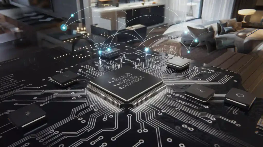
PCB Application in Charging Piles
Power Conversion
Charging piles use advanced pcb application to change AC from the grid into DC for electric vehicles. The charging system pcb has strong parts like rectifiers, inverters, and transformers. These parts work together to give steady power during fast charging.
PCBs in charging piles help change AC to DC. This lets fast charging piles skip the vehicle’s onboard charger. Direct conversion means less energy is lost and charging is faster.
The charging pile uses the pcb for control and communication. It checks voltage, current, and temperature to keep things safe.
PCBs also help with cooling. Heat sinks, thermal vias, and special materials keep the system working well when it gets hot.
The charging system pcb handles a lot of power. This is important for good and steady charging in high-power places.
Charging piles need these pcb application methods to stay safe, reliable, and strong. The power conversion part, built on the pcb, is the main part of every modern charging system.
High-Power Components
Charging piles must handle a lot of power. The charging system pcb uses high-voltage MOSFETs, rectifiers, and inverters with new technology. For example, surface-mount packages like X.PAK let heat escape from the top, which helps cool the pcb. This design makes building easier and lowers electrical loss when it gets hot.
Engineers use isolation tricks, like capacitive isolation and isolated gate drivers, to keep the low-voltage control unit away from the high-voltage power part. This helps stop electromagnetic interference and makes things safer. New charging piles put control units and power devices on one pcb. This saves space and helps with electromagnetic compatibility.
Reference designs from top companies show how to place power modules and other parts on the pcb. These designs focus on keeping things apart, cooling, and where to put each part. The result is a small, strong, and safe charging pile that gives lots of power to electric vehicles.
BMS Integration
The battery management system (BMS) is very important in charging piles. Putting the BMS with the charging system pcb brings some hard problems. The table below shows some main issues:
Technical Challenge | Description |
|---|---|
Circuit Protection Needs | The system must be safe from too much current, surges, ESD, short circuits, and overloads. |
Architecture Impact | Centralized BMS uses long wires and fuses. Modular BMS lowers short circuit risk but costs more. |
Key Protective Components | Fuses, TVS diodes, and diode arrays keep the system safe from voltage spikes and ESD. |
Mechanical Constraints | Vibration, temperature changes, and stress mean the system needs strong parts. |
Physical Design Constraints | Small size, cooling, and sharing space make pcb and BMS work harder together. |
Failure Modes | Overcharging, overheating, and fast discharging can break the battery if not controlled. |
Testing and Collaboration | Early teamwork, strong testing, and working with suppliers make the system better. |
Charging piles must fix these problems to work safely and well. The charging system pcb must sense things well, use many safety steps, and get rid of heat fast. Engineers test the system in real life to find and fix problems early. Good BMS and pcb application together make charging piles safer and better in high-power charging.
Electric Vehicle Charging Systems
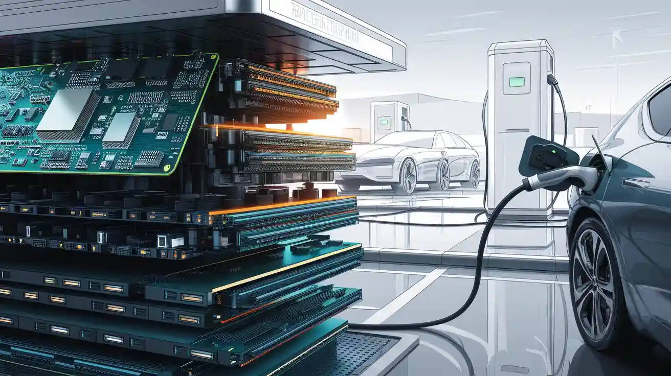
DC Fast Charging
DC fast charging piles are very important for electric vehicle charging. These piles connect straight to the battery packs in new energy vehicles. They do not use the onboard chargers that most cars have. This direct link lets the piles give high DC power, sometimes up to 400 kW. This can charge a car’s battery to 80% in about 30 minutes. The charging pile has many steps inside to change power. These steps include AC input protection, AC-to-DC rectification, power factor correction, DC-to-DC conversion, and DC output protection. Each step uses strong PCBs with power circuits and protection parts.
The table below shows how charging types are used around the world:
Charging Technology | Proportion of Global Installations | Key Characteristics |
|---|---|---|
AC Charging | ~75% | Used most at homes and work; cheaper; has Level 1 (64% of AC) and Level 2 (36% of AC) |
DC Fast Charging | ~20% | Growing fast; needed for public and highway use; gives very fast charging (150-350 kW); costs more to install |
AC charging is used the most, but DC fast charging piles are now needed for public and highway use. These piles help with fast charging, so they are important for new energy vehicles. The PCBs in these piles have high-speed fuses and special parts to protect semiconductors from too much current or voltage. Wires in the charging connector let the pile and car talk to each other for safety. If something goes wrong, the system can stop charging. This keeps both the pile and the car safe during fast charging.
Signal Acquisition
Signal acquisition is very important for safe charging in fast charging piles. Each pile must watch voltage, current, and temperature all the time. This keeps new energy vehicles and their batteries safe. The PCB in the pile has circuits that clean and boost these signals. This helps the pile find problems like too much heat or current and act fast.
Engineers put sensors all over the charging pile to collect data. These sensors watch the charging and send info to the control unit. The PCB looks at this data and turns on safety steps if needed. For example, if it gets too hot, the pile can lower power or stop charging to avoid harm. This control makes sure new energy vehicles get safe and steady charging every time.
Note: Signal acquisition and circuits on the PCB are very important for the safety and good working of fast charging piles. They help stop overcharging, overheating, and other dangers that could hurt cars or batteries.
Communication Interfaces
Modern charging piles use smart communication interfaces to control charging and keep things safe. The PCBA motherboard in each pile has a strong microprocessor. This microprocessor runs charging jobs and keeps new energy vehicles steady. The PCB has many communication interfaces. These let the pile share data with cars, other piles, and the main charging station.
Key jobs of these communication interfaces are:
Changing charging current and voltage based on the battery’s state.
Stopping overcharging or undercharging by watching real-time data.
Cutting off power if there is too much current or voltage.
Helping with data sharing and control for smart charging piles.
These things make charging piles smarter and safer. The communication interfaces also let people check and fix the piles from far away. This helps keep the charging system working well. As more new energy vehicles are used, good communication between piles and cars will be even more important.
Tip: Smart communication interfaces on the PCB are needed for safe and smart fast charging piles. They let the system control and protect in real time, making electric vehicle charging better and safer.
Design Considerations
Materials and Layout
Engineers pick PCB materials with care for fast charging piles. FR-4 is common, but it cannot handle high heat or power here. Aluminum PCBs and ceramic substrates move heat better. These materials help spread heat and keep parts safe. They also let the system use more power without problems. The dielectric constant and loss tangent affect how signals travel. Low numbers keep signals clear and strong. Copper thickness is important too. Thicker copper lets more power flow and lowers resistance, but it can make the PCB bigger. Smooth copper foils help with high-frequency signals. A good PCB stack-up with solid power and ground planes helps with heat and signals. Engineers make power traces wide and short to cut loss and keep things cool.
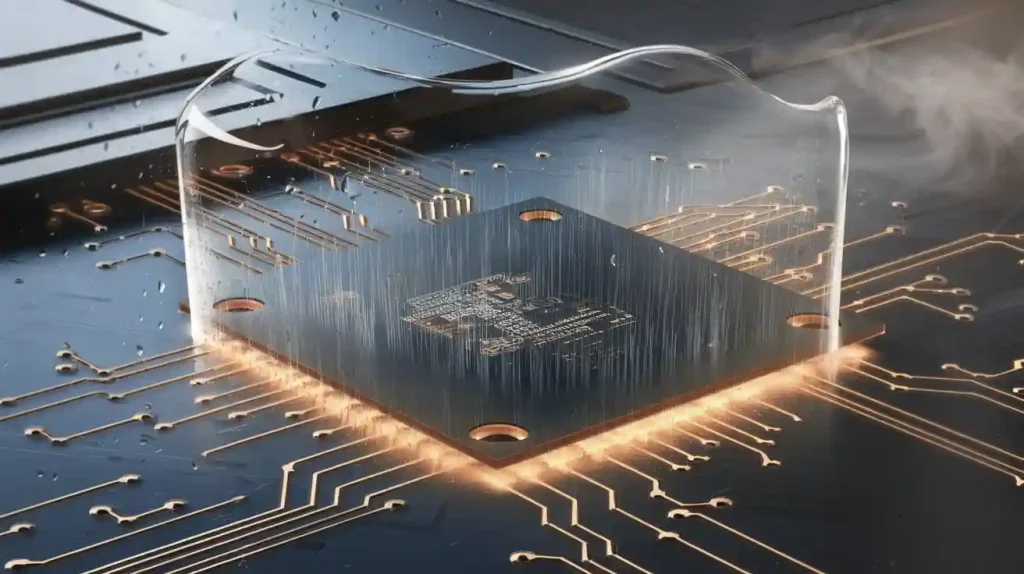
Thermal Management
Fast charging piles get very hot when working. The PCB must move heat away from hot spots to stay safe. Metal-clad PCBs with aluminum or ceramic layers do this job well. They soak up and spread heat fast. Engineers use thermal vias to move heat down to other layers or heat sinks. Power and ground planes also help spread heat out. Sometimes, engineers add heat sinks or bus bars made of aluminum or copper. For very high power, they may use fans or liquid cooling. All these steps keep the PCB and its parts at safe temperatures. Good thermal management helps the charging pile work well and last longer.
Electrical Noise Control
Fast charging piles have lots of electrical noise problems. Noise can come from power switches, fans, or other machines nearby. This noise can mess up signals and cause mistakes. Engineers use many ways to control noise on the PCB. They make strong ground planes to give noise a quick path away. They keep power and signal traces short and far apart. Noisy parts are kept away from sensitive ones. Filters like capacitors and ferrite beads block bad signals. Shields made of copper or aluminum stop noise from getting in or out. Good layout and smart part placement help keep the charging pile safe and working well. These steps protect both the power system and the communication parts inside the pile.
Safety and Compliance
Protection Circuits
Engineers add many protection circuits to fast charging piles. These circuits help keep people and equipment safe. They stop accidents and damage during charging. Some important protection features are:
Emergency stop switches let people or computers stop charging right away.
Leakage protection stops current from escaping and hurting someone.
Overcurrent and short circuit protection stop damage from power surges.
Flame retardant parts lower the chance of fire inside the pile.
Alarms and safety systems find problems and act fast.
Battery state monitoring changes temperature, voltage, and current for safety.
Forced air cooling and heat sinks keep things from getting too hot.
Overvoltage and overheating protection keep all parts safe.
Good relays and special control methods stop relay contacts from sticking.
Electrostatic protection during assembly keeps sensitive parts safe from static.
Self-locking charging sockets and anti-shock designs protect users.
Fire safety steps and lightning protection give more safety layers.
IP54 enclosures keep out dust and water.
All these features work together to make charging safe and steady for people and machines.
Industry Standards
PCBs in charging piles must follow strict world rules. These rules make sure charging is safe and works well everywhere. Some important rules are:
IEC 61851 covers charging ways, connectors, and electrical safety.
ISO 15118 is about how cars and charging stations talk to each other.
SAE J1772 and IEC 62196 tell what connectors and charging steps to use.
UL certifications show the product is safe and works well.
Engineers use these rules so charging piles work safely in many places. Following these rules helps different systems work together and builds trust in public charging. Meeting these rules also keeps people and equipment safe, making charging better for everyone.
Trends in Charging Piles
Miniaturization
Charging piles are getting smaller and lighter. Engineers design miniaturized pcb to save space and use less energy. This helps cut pollution and lets fast charging networks grow. Some new things include:
Smaller copper alloy wires send signals in less space.
Tiny terminal and contact systems, like micro dsub connectors, make good electrical links.
High-performance terminals let engineers use thinner wires, even aluminum, instead of thick copper.
Lighter and smaller electrical interfaces make charging piles easier to put in and fix.
These changes in pcb miniaturization help fit more charging stations in tight spots. They also make the whole system weigh less.
Smart Features
Modern charging piles use smart tech for safety and better charging. Engineers put wireless modules and real-time monitors right on the pcb. The table below shows what these smart features do:
Aspect | Description |
|---|---|
Integration Method | Bluetooth Low Energy modules give wireless communication. |
Real-time Monitoring | Charging data like time, voltage, and current go to phones and cloud systems. |
Remote management and flexible setup for charging piles. | |
Benefits | Less wiring, better use, quick fault alerts, and safer charging. |
Challenges Addressed | Fixing coverage gaps, less interference, and better safety. |
Outcome | Automatic control, fast fault finding, and more reliable charging piles. |
Smart pcb tech lets the system control itself and keep charging safe. This makes fast charging work better for everyone.
Manufacturing Advances
Manufacturers use new tech to make strong pcb for charging piles. Automated SMT and DIP lines build control boards with great accuracy. These ways make sure solder joints are strong and easy to check. SMT lines use machines for mixing solder paste, placing parts, and checking them. DIP lines put in plug-in parts and do wave soldering. Using both helps make high-power charging piles that meet tough quality rules.
The world pcb market for charging piles is growing fast. Experts think it will hit $7.8 billion by 2033. This is because of new tech, more electric cars, and government help. More money for charging piles will keep pushing pcb tech ahead. This will make future charging piles safer, smarter, and more efficient.
PCBs are very important in fast charging piles for vehicles. Engineers make special designs to handle lots of power and heat. They also work to keep everything safe. Some good ways to do this are:
Making sure the circuits are not too hard to follow, so power flows well.
Adding safety parts like fuses and surge protectors to stop problems.
Making sure heat can leave the system and signals stay clear.
To make strong and modern charging piles, experts suggest:
Using thick copper and many layers in the PCB.
Building PCBs quickly to test and improve them fast.
Adding smart cooling and safety systems to protect the pile.
These ideas help all kinds of vehicles charge safely and work well every time.
FAQ
What materials do engineers use for PCBs in fast charging piles?
Engineers pick aluminum or ceramic substrates for high-power piles. These materials help move heat away and keep things working well. FR-4 is used in low-power piles, but it does not move heat as well. Advanced piles need materials that handle heat better.
How do PCBs improve safety in charging piles?
PCBs help keep charging piles safe by adding protection circuits. These circuits stop too much current, too much voltage, and leaks. Engineers also use materials that do not burn easily and strong insulation. This helps stop accidents from happening.
Why is thermal management important for charging pile PCBs?
Thermal management keeps the PCB and its parts cool. Good heat control stops overheating, which can break parts or make them fail. Engineers use heat sinks, thermal vias, and special materials to move heat away from hot spots.
What role does the BMS play in charging piles?
The Battery Management System (BMS) checks battery health and charging. It works with the PCB to watch voltage, current, and temperature. This teamwork stops overcharging and helps the battery last longer.
Can charging piles communicate with electric vehicles?
Yes. Charging piles have communication interfaces on the PCB. These let the pile and car share data about charging, safety, and status. This real-time talk keeps charging safe and fast.