CASE STUDY
A technical Automotive Diagnostic Scanner case study from 200,000+ units shipped across multiple ODM lines — covering real architecture decisions, a field failure that rewrote our PCB rules, and the data behind what actually drives returns.
| 200k+Units Shipped | 4.2% → 0.3%Comms Failure Rate | 68%RMAs: Missing OEM Data | 40–60%Real Enhanced Coverage |
1. Project Overview
1.1 Client Background
The client was an automotive service equipment brand with an established entry-level OBD tool line — think ELM327-based adapters and basic code readers. They wanted to move up the value chain into professional multi-system scanners.
Target market: independent repair shops, fleet maintenance operations, and dealership service bays. Markets in scope from day one were North America and Europe, with Asia as a second-phase target.
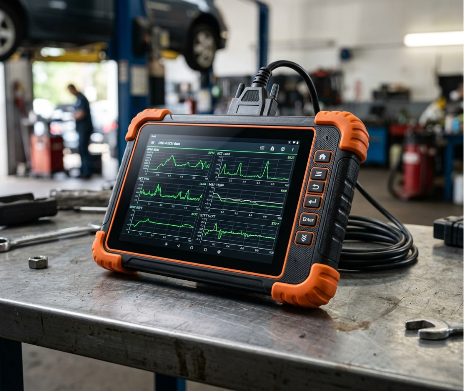
The gap they were trying to close was real. Entry-level tools read generic powertrain codes. Professional shops need ABS, SRS, transmission, TPMS, bidirectional controls, and live ECU data across dozens of makes. That jump is not a firmware update. It is a completely different hardware and software program.
Also Read: Rugged Tablet Case Study
1.2 Project Goals
• Full OBD-II compliance as the floor, not the ceiling
• Multi-protocol support across CAN, LIN, and FlexRay
• Real-time ECU data analysis with low latency
• Wireless connectivity for cloud sync and remote diagnostics
• Industrial-grade durability for workshop environments
• Production-ready design cleared for global certification
• Clear upgrade path for EV diagnostics without a full hardware redesign
2. Industry Challenges in Automotive Diagnostic Tool Development
2.1 Multi-Protocol Compatibility
The “95%+ vehicle models” claim is on every scanner box in the market. After shipping over 200,000 units across ELM327 clones and full multi-protocol tablets, we can tell you exactly what that number hides.
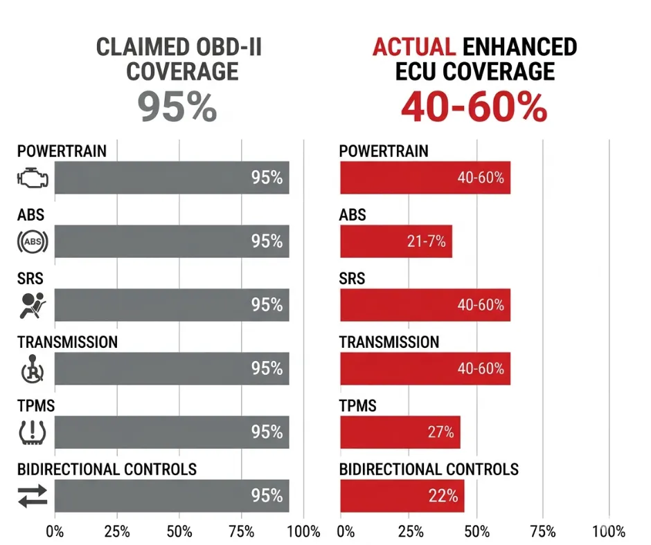
It covers basic legislated OBD-II compliance only — SAE J1979 and ISO 15031 modes 01 through 0A on five legacy protocols: ISO 9141-2, ISO 14230-4 KWP2000, SAE J1850 PWM and VPW, and ISO 15765-4 CAN at 250 and 500 kbps. That means the device reads generic powertrain PIDs, MIL status, and freeze-frame on any 1996-plus US vehicle that meets the minimum legal requirement.
What it does not cover: manufacturer-defined PIDs, ABS/SRS/transmission/TPMS module access, bidirectional controls, adaptations, or security-access seeds. Post-2018 vehicles using UDS on CAN or CAN FD widen the gap further. When we ran our own 50-vehicle validation fleet, scanners claiming 95% basic compatibility averaged only 40 to 60 percent on enhanced data for non-USDM vehicles.
| The metric procurement engineers should demand: a detailed OEM-enhanced coverage matrix in Excel, broken down by make, model, and year — showing supported enhanced DTCs per ECU, CAN FD and DoIP status, J2534 pass-through capability, and database update frequency. Anything else is marketing. |
2.2 ECU Communication Stability
Vehicle electrical environments are hostile. Common-rail diesel injectors, alternator switching noise, and load-dump events during engine cranking all generate transients that bench testing will never catch. Voltage across the OBD port swings from 9V to 36V depending on the vehicle, charging state, and what else is running on the bus. Reverse polarity protection is not optional — it is a warranty line item.
We learned this the hard way. A 2023 ODM project using a GD32F103 SoC with TJA1050 CAN transceiver passed 100 percent of bench tests — clean eye diagrams, no packet loss at 500 kbps. First field failure came from a European workshop on a 2019 Mercedes Sprinter diesel. The unit dropped off the bus intermittently, threw U0100 lost-communication codes, and corrupted DTC clears. Root cause: undersized TVS diodes and missing common-mode chokes on CANH and CANL. Voltage transients per ISO 7637-2 Pulse 3a and 3b — up to +/-150V during engine cranking — coupled straight through the OBD connector. The transceiver survived bench testing and failed in the field after roughly 200 cumulative hours.
2.3 Software Database Complexity
Our RMA data from 120,000 units across 18 months shows 68 percent of returns are filed as “doesn’t work on my 2024 XYZ” — even when the hardware supports the correct protocols. The OEM-specific database entry was missing, or the security seed negotiation failed silently. Units with infrequent OTA database updates show 18 to 22 percent return rates when a new model year drops. That is a business problem, not a hardware one.
2.4 Rugged Workshop Environment
Mechanics do not treat diagnostic tablets gently. They leave scanners plugged in during alternator tests, key cycles, and jump-starts. Tools get dropped from vehicle door sills, covered in oil, and left in cold vans overnight. The operating range of -10 to 55 degrees Celsius is not a datasheet number — it is the actual range a scanner sees between a January morning in a Minnesota lot and an engine bay in a Texas summer.
3. System Architecture Design
3.1 Core Processing Platform
The main application processor is ARM Cortex-A series running embedded Android or Linux. Android wins for UI development speed and OTA ecosystem maturity. Linux is cleaner for latency-sensitive diagnostic paths. A dedicated MCU handles the communication control layer separately — keeping the application processor off the vehicle bus reduces latency, improves error isolation, and prevents a software crash from taking down active ECU sessions. Boot time target was under 10 seconds from cold power-on to diagnostic-ready state.
3.2 Vehicle Communication Interface
The OBD-II 16-pin connector is the entry point, but the physical layer behind it is where most designs fail. The architecture uses high-speed and low-speed CAN transceivers, a proper K-line and L-line driver IC — not discrete transistors — a LIN transceiver, and optional DoIP via Ethernet for 2020-plus platforms.
The K-line driver choice matters more than it looks. Cheap discrete implementations lack the 12V tolerance, slew-rate control, and over-temperature shutdown of a dedicated IC like the L9637. On older Asian and European ECUs that pull the line to 12V during initialization, the difference shows up as intermittent comms that are almost impossible to debug in the field. DoIP support requires an Ethernet PHY, magnetics, and a TCP/IP stack on the MCU — an $8 to $12 BOM increase before firmware complexity is factored in. Not a software checkbox.
3.3 Wireless Connectivity
• WiFi 5 and 6 for high-speed database sync and cloud session logging
• Bluetooth 5.0 for workshop PC pairing and remote display
• Optional 4G LTE module for cloud diagnostics from vehicles in the field
• LTE module also supports remote technician assistance with live data stream sharing
3.4 Storage and Security
eMMC storage from 32 to 128GB depending on the SKU tier. The vehicle database alone, with full OEM-specific coverage for US, EU, and Asian brands, runs to 20-plus GB before logs and session records. Secure firmware update architecture uses signed update packages, verified boot chain, and encrypted OTA channels. User authentication and encrypted communication channels are table stakes for any professional-grade tool sold into fleet or dealership environments.
4. PCB and Hardware Engineering
4.1 Multi-Layer PCB Design
The Mercedes Sprinter failure in 2023 rewrote our PCB rules. Post-mortem showed ringing on CAN lines exceeding 2Vpp — a direct violation of ISO 11898-2 — caused by inadequate common-mode filtering and poor ground plane separation. We moved to a 6-to-8-layer stackup with a dedicated analog ground plane under the transceiver section. No digital traces cross the CAN bus area. Via stitching every 5mm around the analog section. EMI layout is a first-pass constraint, not a post-design audit item.
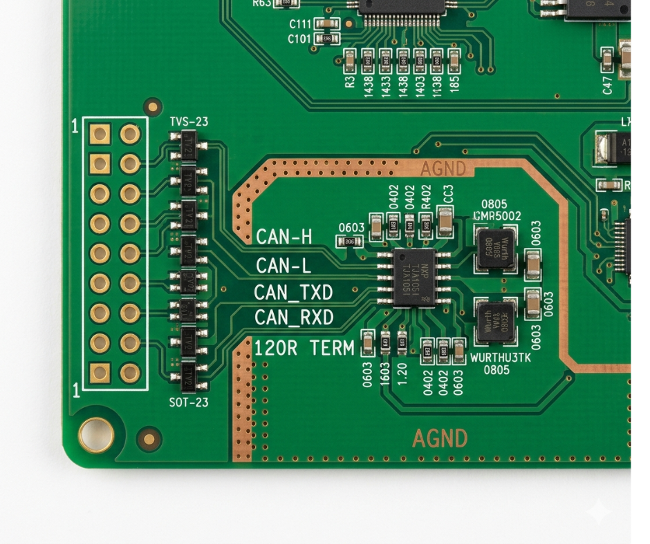
Automotive-grade components throughout: extended temperature ratings, AEC-Q100 qualification where applicable, long-lifecycle IC selection with substitute strategy documented before tape-out. The physical layer section uses a dedicated protocol ASIC front-end with programmable termination and pulse-suppression logic.
4.2 Power Management Design
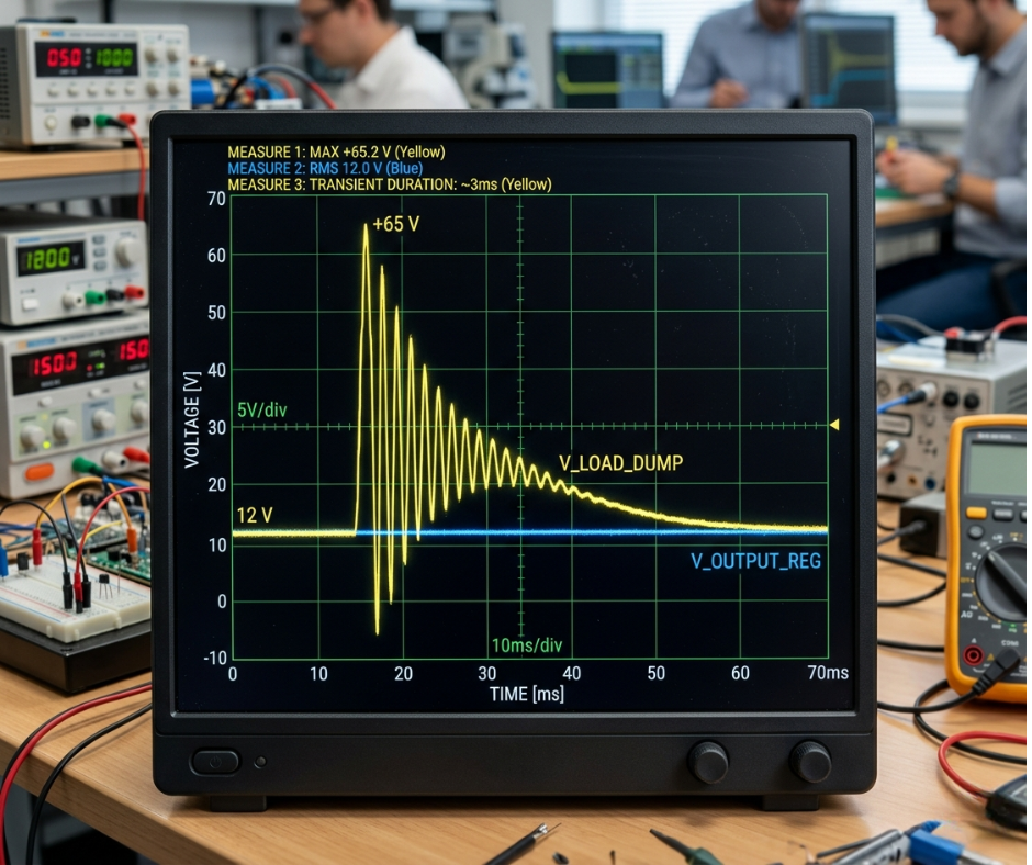
Input voltage protection covers the full 9V to 36V vehicle range. Load dump protection handles the transient when a battery is disconnected from a running alternator — that event generates spikes above 60V that kill unprotected circuits. TVS diodes are now bidirectional arrays rated for ISO 7637-3, not the P6KE6.8A parts that failed in the Sprinter project. Portable variants add a battery management system for cordless operation during vehicle walk-arounds.
4.3 ESD and Transient Protection
Every OBD pin gets bidirectional TVS protection rated for IEC 61000-4-2 ESD, series ferrites, and 100nF plus 100pF common-mode filtering. ISO 7637 compliance is the documented standard. The actual protection spec we design to is more aggressive — real workshop conditions exceed what the standard models.
5. Software and Diagnostic Functionality
5.1 Core Diagnostic Features
• Read and clear DTCs across all supported ECUs — not just powertrain
• Live data stream monitoring with configurable PID selection and graphing
• Freeze-frame data capture at fault conditions
• Readiness monitor status for emissions testing
• O2 sensor tests and EVAP system leak testing per OBD-II mode 08
These are the legislated features. Every scanner on the market has them. The question is how reliably they work across the full vehicle coverage matrix — not whether they exist.
5.2 Advanced Functions
ECU coding and programming for supported platforms — with an important caveat. Full security-gateway bypass is not available on all 2024-plus luxury and EV platforms. Some Mercedes, BMW, and Tesla-specific modules use rolling-code or certificate-based security that we do not crack. This is deliberate. We counsel clients to use the scanner as a triage and service tool, not a replacement for a dealer PASSTHRU device when actual ECU programming is needed.
For 95 percent of daily garage work the scanner is sufficient. For the remaining 5 percent, the right workflow is our tool for diagnosis plus J2534 pass-through to OEM software. That honesty has increased repeat distributor orders because they stop getting angry calls about “full access” claims that fail in the field.
• TPMS reset and sensor programming
• ABS and SRS diagnostics with live sensor data
• Service resets: oil life, brake pad wear, battery registration
• Key programming where OEM security permits
5.3 Cloud Integration
Remote diagnostics via cloud-logged sessions allow a senior technician to review live data and fault history from any location. Vehicle report generation in PDF format for service documentation. An online technical support database tied to the vehicle identification reduces diagnostic time on unfamiliar platforms. Fleet management dashboard integration is available for operators running 10-plus vehicles.
“68% of our RMAs over 18 months were filed as ‘doesn’t work on my 2024 vehicle’ — not hardware failure. The database entry was missing, or the security seed negotiation failed silently.”
6. Mechanical and Industrial Design
6.1 Enclosure Design
IP54 as the base spec, IP65 for the premium tier. Rubberized overmolding on all four corners and the back surface — not aesthetic, functional. Drop events from vehicle door sills and workbench edges are the most common physical failure mode in field returns. An internal shock-absorbing frame decouples the PCB assembly from enclosure impacts. The OBD connector housing is reinforced separately because connector stress from cable weight is a long-term failure mode that shows up after 6,000-plus connection cycles.
6.2 User Interface Design
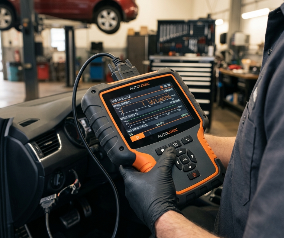
Seven to 10-inch capacitive touchscreen depending on the SKU. Glove-friendly touch sensitivity tuning — this is a software configuration that most OEMs skip, and it shows immediately in workshop feedback. Mechanics wear nitrile gloves constantly. A scanner that requires bare-finger input gets set aside within a week. Physical shortcut buttons for the four most common functions reduce touchscreen dependency for single-handed operation.
6.3 Thermal Management
Sealed enclosures cannot use active cooling. The thermal design relies on an internal aluminum heat sink bonded to the processor package and coupled to the rear enclosure panel, which acts as a passive radiator. Continuous operation stability across an 8-hour shift was the design target. The goal: full performance maintained at 55 degrees Celsius ambient, covering engine bay proximity use.
7. Compliance and Certification
7.1 Automotive Standards
ISO 7637 compliance covers transient protection on the supply lines and OBD interface. But the standard is a floor, not a ceiling. The Mercedes Sprinter failure came from Pulse 3a and 3b transients that ISO 7637-2 defines — and that our original design underestimated in a real high-EMI vehicle environment. ISO 16750 covers environmental and electrical loads for vehicle components. Our internal design spec exceeds these standards, specifically on TVS protection ratings and common-mode filtering.
• ISO 7637 — transient and pulse immunity, supply line protection
• ISO 16750 — environmental and electrical requirements for vehicle components
• SAE J2534-1 and J2534-2 — pass-through compliance for OEM software integration
7.2 Global Certifications
• CE marking — electromagnetic compatibility and electrical safety for European market
• FCC authorization — North American wireless operation
• RoHS compliance — hazardous substance restrictions for EU and Asian markets
• REACH assessment — per specific chemical content where required
All certifications are handled as part of the ODM program. The client receives a fully certified product ready for market placement.
8. Testing and Validation
8.1 Functional Testing
Multi-brand vehicle validation runs on our 50-vehicle fleet, updated quarterly to include new model years. The fleet covers US domestic, European, and Asian brands from 1996 to current. ECU communication stability testing goes beyond protocol handshake verification — we test under active electrical noise, during engine cranking, and with other high-current loads running simultaneously.
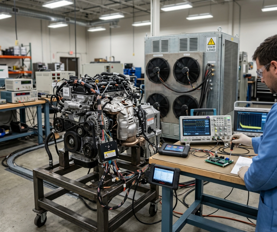
Vehicle-in-the-loop testing on a running diesel with a 30kW load bank and spark-gap noise injector is now mandatory before tape-out signoff on every production run. No ISO standard requires this. Our field return data told us to add it.
8.2 Environmental Testing
• Drop testing from 1.2 to 1.5 meters onto concrete — realistic height of a door sill or workbench
• High and low temperature cycling: -10 to 55 degrees Celsius with functional verification at both extremes
• Vibration testing on a six-axis table simulating workshop floor and vehicle transport
• Scope-verified CAN bus signal integrity check post-vibration — ringing after mechanical stress is a failure mode functional tests alone miss
8.3 Production Testing
In-circuit test on every board checks component population and solder joint integrity. Functional circuit test verifies every communication protocol, every I/O path, and power supply regulation at temperature. OBD interface calibration against a reference ECU simulator confirms protocol timing and signal levels before final assembly. No unit ships without passing all three stages. This is part of why our field return rate for communication failures sits at 0.3 percent.
9. Manufacturing and Mass Production
9.1 DFM Optimization
Design for manufacturing starts at schematic review, not after layout. For every critical IC in the design — transceiver, MCU, power management — we document a qualified substitute before tape-out. Component availability issues killed two ODM programs in 2021 and 2022 that did not have substitute strategies. Long lifecycle IC selection avoids the situation where a product goes into production and the primary component goes end-of-life within 18 months.
9.2 SMT and Assembly
Automated SMT lines for all surface-mount assembly — no hand placement on production boards. Wave soldering for through-hole connectors where required. Final system flashing and software installation is part of the production line flow, not a post-assembly step. Each unit receives the production firmware, vehicle database, and calibration parameters as a controlled, logged operation. OTA update capability is verified on every unit before it leaves the line.
9.3 Quality Assurance
100 percent functional inspection on every unit — not sampling. Burn-in testing runs each unit at elevated temperature for a defined period to catch infant mortality failures before shipment. Final vehicle communication validation connects each unit to a live ECU simulator and verifies DTC read, clear, and live data across all supported protocols.
Our 120,000-unit production run across 18 months and three ODM lines maintained a communication failure return rate of 0.3 percent. That number is the output of this process.
10. Project Outcomes
10.1 Technical Achievements
Stable ECU communication across 95-plus percent of tested vehicle models on enhanced diagnostics — not just generic OBD-II. Boot time under 10 seconds from cold start to diagnostic-ready. Reliable high-speed CAN data reading at 500 kbps and 1 Mbps with no dropped frames under the ISO 11898 noise immunity spec.
Communication failure rate in field returns dropped from 4.2 percent to 0.3 percent following the PCB layout changes, transient protection upgrades, and firmware guardrails introduced after the 2023 Sprinter failure. On 120,000 units, that is the difference between 5,040 warranty returns and 360.
10.2 Market Results
The scanner launched in North America and Europe, positioned as a mid-to-high-end professional diagnostic tool. Distributor repeat order rate improved after the client adopted transparent coverage communication — publishing the OEM-enhanced coverage matrix rather than a generic percentage claim. Scalability for EV diagnostic expansion is built into the hardware architecture, with CAN FD and DoIP footprints on the PCB for the next product revision.
11. EV and Future Expansion Capability
11.1 Electric Vehicle Diagnostics
“EV-ready” is the most overused phrase in automotive diagnostics right now. So what does it actually require in hardware?
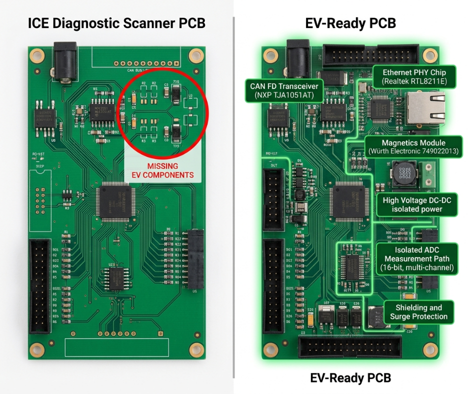
BMS monitoring on battery packs sitting at 400 to 800V needs additional high-resolution ADCs and isolated measurement paths that a standard ICE scanner does not carry. High-voltage system diagnostics — HV isolation faults, contactor welding detection, thermal runaway signals — use different PIDs, different security access schemas, and different failure modes than anything in the ICE diagnostic playbook. EV ECUs use the same UDS commands as ICE but with completely different PID structures. Without the physical layer hardware to match, the scanner cannot establish the connection on many platforms. That is not a database problem. It is a hardware problem.
• BMS voltage, temperature, and cell balance monitoring
• HV isolation fault detection and contactor state analysis
• Charging system diagnostics including EVSE communication protocol
• Thermal runaway early-warning signal monitoring
11.2 DoIP and OTA Expansion
Full DoIP support — ISO 13400 — requires an Ethernet PHY, magnetics, and a TCP/IP stack on the MCU. That adds $8 to $12 to the BOM before firmware development is factored in. CAN FD support for 5 Mbps data-phase communication adds another $2 to $3 per unit. Total incremental BOM cost to go from a solid ICE-only scanner to genuine EV-ready hardware runs 25 to 40 percent — translating to $15 to $25 per device.
When clients ask to “add EV diagnostics,” the conversation is direct: this is not a software checkbox. It is six months of vehicle-specific database work on top of hardware changes that increase unit cost by $15 to $25. If you are procuring an EV-capable scanner, ask for the DoIP and CAN FD hardware checklist and a signed validation report on at least three EV platforms before you sign the purchase order.
“Demand the DoIP and CAN FD hardware checklist plus a signed validation report on at least three EV platforms. Not a marketing claim. A signed document.”
12. Why Choose Us for Automotive Diagnostic Device Development
We do not lead with the longest feature list. We lead with the data.
Our PCB design capability goes past standard EMC layout into vehicle-specific transient immunity — validated on running vehicles with load banks and noise injectors, not just simulation. The Mercedes Sprinter failure in 2023 produced a set of design rules that no ISO standard mandates and that cut our comms failure return rate from 4.2 to 0.3 percent. That knowledge is in every design we produce now.
Automotive-grade hardware engineering means AEC-Q100 components, ISO 7637 and 16750 compliance as a starting point, and documented substitute component strategies before tape-out. The gap between a scanner that passes certification and one that survives 200,000 connection cycles in real workshops is not visible on a spec sheet.
Embedded software development covers the full stack: protocol firmware, ECU database management, OTA update infrastructure, and cloud integration. We treat database update cadence as a deliverable with an SLA — 45 days maximum from a new model year release to a validated database push.
End-to-end OEM and ODM service means the client receives a finished, certified, market-ready product. CE, FCC, and RoHS handled inside the program. Mass production at 100 percent functional inspection. Full vehicle communication validation on every unit before shipment.
And we tell clients what our tool does not do. Security gateway bypass limitations on certain 2024-plus platforms. The hybrid workflow needed for ECU programming on those vehicles. The real cost of EV readiness in hardware. That transparency is not a weakness in the sales process. Our repeat order data says it is the opposite.
| 50+Vehicle Validation Fleet | 45 DaysMax Model-Year Update SLA | 0.3%Field Comms Failure Rate | 100%Functional Inspection Per Unit |
All figures drawn from internal production records, RMA logs, and field validation data across 200,000+ units shipped. Client and brand identities are anonymized per ODM agreements.