A power distribution network in pcb design gives each part the power it needs. You need steady power to keep your circuits working right. If your power distribution network is not good, your pcb can have problems like:
Voltage droops can happen when your circuit needs more power fast. This can make things stop working or cause data loss.
Noise interference can show up and mess with sensitive parts. It can also hurt signal quality.
Signal integrity problems like ringing and overshooting can make your data not reliable.
Power Distribution Network Basics
What Is a Power Distribution Network
A power distribution network in a pcb is like veins in your body. It moves power from the main source to every part of the circuit. This network gives each component the right current and voltage. You can see how important this network is in different devices:
In smartphones, the power distribution network takes power from the battery to the CPU, GPU, memory, and display.
In data centers, it sends power to servers, storage devices, and networking equipment.
In modern vehicles, it brings power from the battery to the engine control unit, infotainment systems, sensors, and safety features.
The main job of a power distribution network is to make sure every load gets enough power to work well. You want your pcb to have steady power so all parts work smoothly.
There are new improvements in power distribution network design. Engineers use integrated power delivery modules to make things more efficient. They also try new materials that have lower resistance and better heat control. These changes help your pcb handle more power in smaller spaces.
Advancement | Description |
|---|---|
Integration of IoT | PCBs help IoT devices collect data and watch the grid in real time. |
Advanced Materials | New substrates give better heat flow and stronger insulation. |
Miniaturization | Smaller, better PCBs fit inside tiny smart devices. |
Sustainability | Eco-friendly materials and designs help save energy. |
Why Stability Matters
You need steady power to keep your pcb working without trouble. If your power distribution network is not steady, you can get voltage drops, noise, or even broken devices. Stability means your circuit always gets the right power, even if the load changes fast.
Industry standards help you build a good power distribution network. These rules tell you about trace widths, spacing, and impedance control. They also give safety and electromagnetic interference rules. When you follow these rules, your pcb becomes safer and more reliable.
Tip: Always look at the newest standards before you start your design. This step helps you avoid mistakes and makes sure your pcb meets all the rules.
A strong power distribution network lets you trust your design. You know your pcb will send power where it is needed, so your devices work as they should.
Key PDN Components
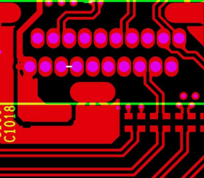
Power Planes and Traces
You make a strong power distribution network by using power planes and traces. Power planes are big copper areas inside the pcb. They help keep voltage steady across the board. This path has low impedance, so power goes everywhere it is needed. Good power plane design keeps voltage stable and cuts down on noise. Wide traces and solid planes stop voltage drops and make your pcb work better.
Power planes also help when power needs change fast. Power and ground planes together make a low-inductance path. This is important for fast digital signals. It helps your power plane work well. You get better signals and less noise.
Tip: Use wide traces and solid planes to keep your pcb steady and make it work well.
Decoupling Capacitors
Decoupling capacitors are very important in your pcb’s power system. You put them close to chips and other parts. They work like small energy tanks. When your circuit needs more power fast, these capacitors give it. This stops voltage from dropping too much. Decoupling capacitors also block sudden surges. This keeps voltage safe. Good power plane design always puts capacitors in the right places.
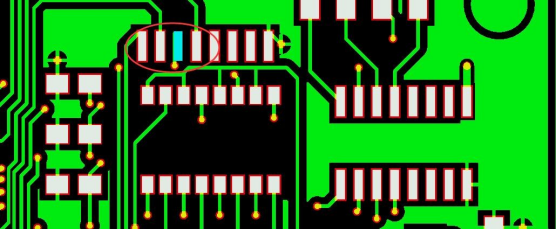
Vias and Ground Planes
Vias connect power and ground planes on different layers of your pcb. You use them to move power between layers. They also give a steady signal reference. Good via placement lowers noise and cuts down on inductance. This keeps signals clean and power strong. Via stitching means adding lots of vias. This gives more paths for current. It lowers impedance and helps your pcb handle more power.
A good ground plane works with your power plane to make a low-inductance path. This is important for fast circuits. You stop voltage swings and keep signals clear. When you focus on power plane design, your pcb works better.
Note: Always check where you put vias and how you lay out ground planes to get the best power plane results.
Main Components of a Power Distribution Network
Power sources
Traces
Planes
Decoupling capacitors
Voltage regulators
Impedance and PDN Performance
Impedance is very important for your power distribution network. You want low impedance when you design a pcb. Low impedance gives steady power to every part. High impedance can cause voltage drops. Voltage drops can make errors or hurt your chips. You must control impedance to keep voltage stable. This helps your pcb work well.
R-L-C Model in PDN
Your power distribution network has resistors, inductors, and capacitors. This is called the R-L-C model. Resistance slows current and makes heat. Inductance fights changes in current. This can cause voltage spikes if loads change fast. Capacitance stores and releases energy. It helps keep voltage smooth.
The R-L-C model lets you guess how your power network will act. You can find weak spots in your design. You might add more capacitors or change trace widths. This makes your power delivery better. Your devices stay safe and work well.
Minimizing Impedance
You should keep impedance as low as you can. Low impedance means less voltage drop and better power. Here are ways to lower impedance:
Use wide traces and solid power planes.
Put decoupling capacitors close to chips.
Add more vias to connect power and ground planes.
Keep power and ground planes close together.
For fast designs, match impedance to your interface type. The table below shows good impedance values for common interfaces:
Interface Type | Impedance Value |
|---|---|
DDR (Single-ended) | 50 ohms |
DDR (Differential pairs) | 100 ohms |
Ethernet (Differential pairs) | 100 ohms |
USB (Differential) | 90 ohms |
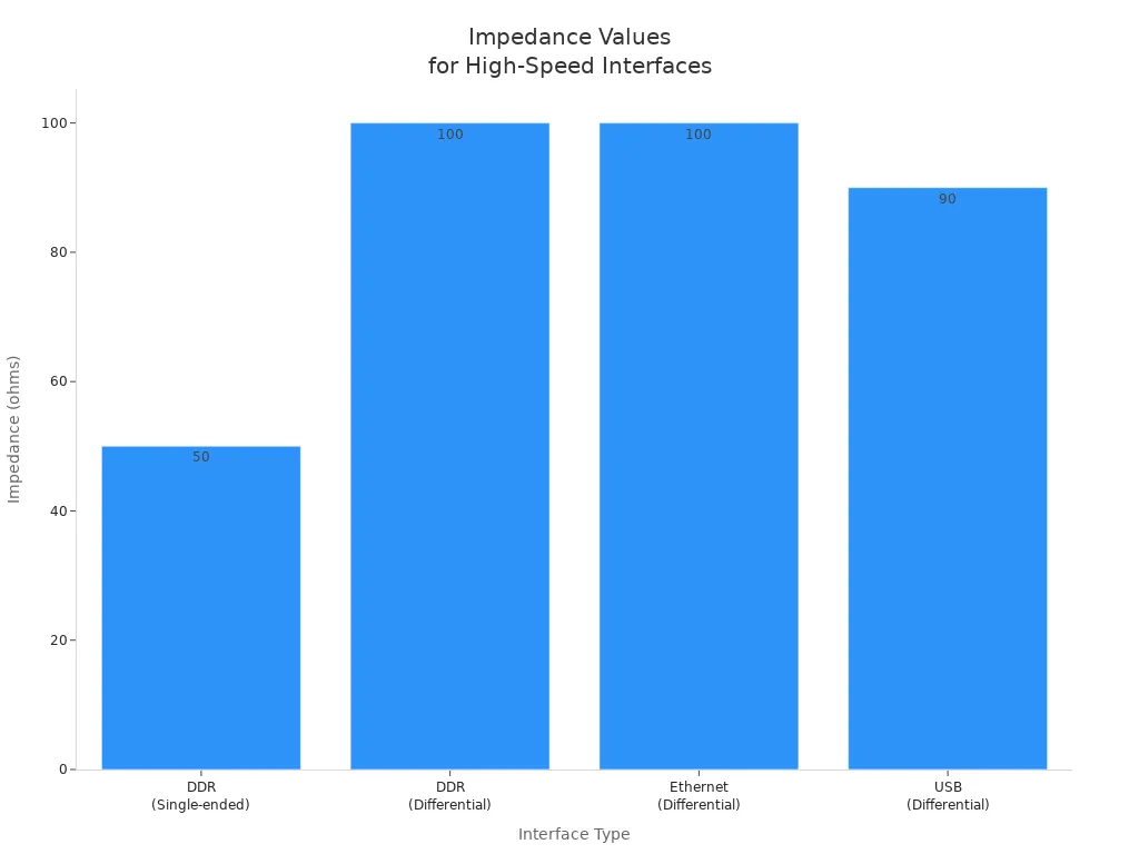
If you keep impedance in these ranges, your pcb gives clean power. This helps you avoid signal problems.
Tip: Always check what impedance your interface needs before you start. This helps you avoid mistakes.
PDN Analysis and Measurement
You need to measure and check your power distribution network. Many tools help you check impedance and other things. The table below lists ways to measure impedance:
Method | Frequency Range | Advantages/Applications |
|---|---|---|
Time-Domain Reflectometry (TDR) | MHz to GHz | Fast, high-resolution; used a lot in the industry. |
Vector Network Analyzer (VNA) | kHz to GHz | Very accurate; good for RF and microwave. |
Impedance Analyzer | Hz to GHz | Accurate; good for passive parts. |
LCR Meter | Hz to MHz | Simple and cheap; used for high-frequency jobs. |
Field Solver (Sigrity X) | N/A | Predicts results before testing; used in design. |
OrCAD X | N/A | Has tools for impedance checks during design. |
You should also look at other things to judge your power network. Here is a table with important metrics:
Metric | Description |
|---|---|
PDN Impedance | Low PDN impedance gives steady power. |
Voltage Ripple | Less ripple means less noise. |
Current Density | Good current density stops hot spots and helps reliability. |
When you measure DC resistivity, you see how current moves. This helps you find places where voltage drops can happen. Measuring loop inductance shows how your network acts when loads change fast. Both tests help you make sure your pcb works in real life.
If you keep impedance low and use the right tools, your pcb gives steady power. This keeps your devices safe and working well. Good checks and tests help you get the best power in every design.
Designing a Well-Designed Power Distribution Network
Define Power Requirements
You need to know what power each part needs first. Make a list of all the parts on your pcb. Write down the current and voltage for each one. This helps you plan for enough power. Use the right copper thickness for your power planes. Many boards use 1.6 mm thick boards and 3 or 4 oz copper. This makes strong power paths. Add ground and power planes for low-impedance paths. Put decoupling capacitors near power pins to handle voltage changes.
Tip: Making a clear list of power needs helps stop voltage drops and keeps your pcb steady.
Component Placement Strategies
Where you put parts is important for power delivery. Place parts so power traces are short and direct. This lowers resistance and keeps voltage steady. Put decoupling capacitors close to chips. Good placement helps with heat too. Keep hot parts away from each other. Do not put sensitive parts near noisy power lines. Make sure everything fits in the case and does not block other parts.
Place parts for short, direct power paths.
Put capacitors within 5 mm of power pins.
Keep hot parts apart for better cooling.
Simulation Tools
Simulation tools help you check your power network before building it. These tools show where voltage drops or noise might happen. You can fix problems early. Here is a table of common tools:
Tool Name | Key Features |
|---|---|
OrCAD | Simulates power delivery, voltage drop, and noise. Easy to use. |
Ansys SIwave | Checks power and signal integrity, EMI, and heat. Optimizes capacitors. |
Siemens Xpedition | Known for strong power delivery analysis. |
Use these tools to test your design. You save time and money by finding problems before making your pcb.
Common Mistakes to Avoid
Some mistakes can hurt your power delivery. Do not use thin traces for high-current paths. Always use wide traces or power planes. Put decoupling capacitors close to power pins. Never skip ground and power planes. These planes keep power steady and lower noise. If you forget these steps, your pcb may have voltage drops or not work right.
Do not use thin traces for power.
Do not put capacitors far from chips.
Never skip ground and power planes.
Overcoming PDN Challenges
High-Speed Circuits
High-speed circuits can be tricky to design. Fast signals need steady power all the time. You have to handle quick changes in current. Noise and electromagnetic interference can mess up your signals. Keeping impedance low is important for every signal speed. There is not much space, so you must fit parts close together.
You have to deal with fast current spikes.
You need to keep noise and EMI under control.
You should keep impedance low for all signals.
You often work in small spaces.
If you do not check your design well, you might pick the wrong capacitors. Noise, impedance, and stability all affect each other. You need to check every part of your power system.
Multiple Power Rails
Many new boards use more than one power rail. Each rail needs steady power to work right. You must plan well to stop voltage drops and current issues. The table below shows problems you can have with many rails:
Challenge | Explanation |
|---|---|
You must keep voltage steady on every board. If voltages do not match, you can get problems. | |
Voltage drops and current imbalances | Resistance and inductance in connectors can lower voltage and hurt how things work. |
System-level power planning | Each board uses different amounts of power. You must size power supplies to stop overheating or drops. |
You need to make sure each rail gets enough power. Good planning helps you avoid trouble and keeps your pcb working well.
Troubleshooting Instability
Sometimes your power delivery network is not stable. You can fix many problems with easy steps:
Look at your board for damage like burned parts or broken traces.
Use a multimeter to check voltage at important spots.
Use an oscilloscope to see if signals look right.
Test each part to make sure it works.
Compare your board to a good one to find what is different.
Things around you can also cause problems. High heat can make your pcb weak and break it. Humidity, shaking, and EMI can make your power less steady. You need to know about these risks and design for them. Good power delivery keeps your devices safe, even when things get tough.
Tip: Always test your power delivery network in real life. This helps you find problems before your pcb is used.
You get lots of good things from a well-designed power distribution network in your pcb. The table below shows how steady power helps your board work better and last longer:
Benefit | Explanation |
|---|---|
Stable Power Delivery | Makes your devices work well and stops problems. |
Enhanced Circuit Performance | Makes all parts work better and more reliably. |
Improved Thermal Management | Helps your pcb stay cool and work for more years. |
To keep your power system strong, try these tips: Plan your power setup early. Match impedance and keep power paths short. Put decoupling capacitors close to power pins. Use wide traces and solid ground planes.
You can find more by looking at trusted resources and industry guides.
FAQ
What is the main goal of a power distribution network in PCB design?
You want your PDN to deliver steady power to every part on your board. This helps your circuit work without errors or noise.
Why do you need decoupling capacitors?
Decoupling capacitors store energy close to your chips. They give quick bursts of power when needed. This keeps voltage steady and stops sudden drops.
How can you lower PDN impedance?
You can use wide traces, solid power planes, and place decoupling capacitors near chips. Add more vias to connect layers. These steps help keep impedance low.
What happens if your PDN is unstable?
If your PDN is unstable, you may see voltage drops, noise, or even damaged parts. Your board may not work as expected.