In electronics, decoupling capacitors help keep voltage steady. They also reduce noise in circuits. These small parts act as shields between power sources and devices. They stop sudden voltage drops and block high-frequency noise.
New technology has made decoupling more important. Smaller devices need better capacitors. Multi-layer ceramic capacitors (MLCCs) are now common. They are small but store a lot of charge. Modern capacitors can handle very high heat, up to 200°C. This makes them useful for high-voltage and hot environments. These changes help meet the needs of today’s gadgets and energy systems.
Decoupling capacitors give a clear path for high-frequency noise. This makes electronic designs more reliable. They also keep power steady, even in tough conditions.
Key Takeaways
Decoupling capacitors keep voltage steady by storing and releasing energy fast. They protect delicate parts like microchips.
These capacitors stop high-frequency noise, keeping signals clear in devices like speakers and phones.
Placing decoupling capacitors close to ICs makes them work better. This lowers interference and improves how circuits perform.
Picking the right capacitor means checking things like self-resonant frequency and resistance to make sure it works well.
Using different capacitor sizes together controls many frequencies. This makes electronics more stable and work better.
Why Do We Need Decoupling Capacitors?
Keeping Voltage Steady in Circuits
Decoupling capacitors help keep voltage stable in circuits. They store energy and release it when needed. If a circuit suddenly needs more power, these capacitors act fast. They stop voltage drops and protect sensitive parts like microchips.
These capacitors are placed near power pins of chips. Being close helps them work quickly when power changes. In fast circuits, steady voltage is very important. Without decoupling, voltage changes can cause errors or damage parts.
Cutting Noise and Making Signals Clearer
Circuits often face noise from power supplies or signals. Decoupling capacitors block this noise by sending it to the ground. This keeps the circuit working smoothly.
For example, in audio systems, noise can ruin sound quality. In communication devices, it can mess up signals. Decoupling capacitors fix this and make devices work better. They are very useful in circuits with fast signals where even small noise matters.
Improving Power Supply Stability
Power supply stability means keeping circuits steady even if power changes. Decoupling capacitors help by sending power supply changes to the ground. This stops power changes from affecting the circuit.
High-performance amplifiers need these capacitors to stay stable. Big capacitors handle low-frequency noise, and small ones handle high-frequency noise. Together, they keep circuits steady across all frequencies. Without them, power changes could cause noise or lower performance.
How Do Decoupling Capacitors Work?

Separating AC and DC Signals
Decoupling capacitors split AC signals from DC signals in circuits. They act like shields, keeping power clean and steady. When AC signals mix with DC signals, noise and voltage changes happen. These capacitors stop this by keeping the signals apart.
On printed circuit boards (PCBs), these capacitors are very important. They keep signals clear and power stable. Placing them correctly stops AC signals from disturbing DC signals. Without this, circuits might get noisy or work less efficiently.
Main Benefits of Separation:
Cuts down on noise.
Stops voltage changes.
Keeps signals clear.
Filtering High-Frequency Noise
Decoupling capacitors block high-frequency noise by giving it a path to the ground. This noise often comes from fast power changes or quick signals. By grounding the noise, they protect sensitive parts.
The capacitor’s ability depends on its resistance and inductance. Low-resistance and low-inductance capacitors work best for high-frequency noise. Studies show these capacitors lower noise by 10 dB. They also keep voltage changes between 0.48V and 0.10V.
Metric | Value |
|---|---|
Voltage change range | 0.48V to 0.10V |
Noise reduction | 10dB |
Loop impedance needed | 1 ohm or less |
Inductance for impedance | about 1.6nH or less |
These capacitors are vital for fast circuits. Even small noise can cause problems. Picking the right capacitor improves how circuits work.
Keeping Voltage Stable During Changes
Voltage spikes or drops can cause errors in circuits. Decoupling capacitors fix this by giving extra power during sudden changes. This keeps voltage steady and parts working well.
Tests show circuits without decoupling capacitors have more noise and less stability. With these capacitors, voltage stays steady, avoiding glitches and power issues.
Bigger capacitors, like 1 µF, handle changes better than smaller ones, like 100 nF. But you also need to check resistance and inductance when designing circuits. These factors affect how well capacitors stabilize voltage.
Using decoupling capacitors protects circuits from voltage problems. They ensure devices work smoothly, even in tough situations.
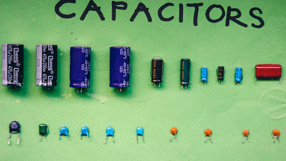
Types of Decoupling Capacitors
Ceramic Capacitors: Blocking High-Frequency Noise
Ceramic capacitors are common in electronic circuits. They are small, cheap, and great for blocking high-frequency noise. These capacitors use ceramic material to store energy. This helps them react quickly to voltage changes. Their low resistance and inductance make them perfect for filtering noise.
You often see ceramic capacitors near chips to keep voltage steady. They work well in fast circuits like microprocessors. For example, a 0.1 µF ceramic capacitor can block noise in the MHz range. Their tiny size makes them ideal for small, modern devices.
Electrolytic Capacitors: Smoothing Low-Frequency Noise
Electrolytic capacitors are better for low-frequency noise. They store more energy than ceramic capacitors. This helps them smooth out slow power changes.
These capacitors use a liquid layer to hold energy. This gives them high capacitance but also higher resistance. They are not as good at blocking high-frequency noise. You’ll find them in power supplies to stabilize voltage. For example, a 100 µF electrolytic capacitor handles noise in the Hz to kHz range. They are bigger than ceramic capacitors but handle large voltage changes well.
MLCC (Multi-Layer Ceramic Capacitors): Filtering High-Frequency Signals
MLCCs are special ceramic capacitors for high-frequency filtering. They have many layers of ceramic and metal. This increases their energy storage while staying small. MLCCs block high-frequency noise effectively, especially in RF circuits.
For example:
MLCCs can reduce noise by 86 dB at 1.64 MHz with 44 µF.
A 0.47 µF MLCC works well for signals from 0.5 to 500 MHz.
These capacitors are used in communication devices to block unwanted signals. Their small size and ability to handle high frequencies make them popular in modern electronics.
How to Choose a Decoupling Capacitor
Things to Check: SRF, ESR, ESL, and PDN Impedance
When picking a decoupling capacitor, check a few key things. These include self-resonant frequency (SRF), equivalent series resistance (ESR), equivalent series inductance (ESL), and power distribution network (PDN) impedance. Each one helps your circuit work better.
Self-Resonant Frequency (SRF): This is when the capacitor stops acting like a capacitor and starts acting like an inductor. Look for SRF between 20–30 MHz for most uses.
Equivalent Series Resistance (ESR): Lower ESR, around 20–50 mΩ, reduces power loss and blocks noise.
Equivalent Series Inductance (ESL): Low ESL is important for fast circuits. It lowers impedance at high frequencies.
PDN Impedance: To keep power steady, match your capacitor’s SRF to the PDN impedance peaks. Use tools to find these peaks.
Metric | Value Range |
|---|---|
Self-Resonant Frequency (SRF) | 20–30 MHz |
Equivalent Series Resistance (ESR) | 20–50 mΩ |
Place capacitors close to the chip to reduce unwanted inductance. Using several capacitors together lowers inductance even more, improving the circuit.
Choosing Capacitors for Digital PDNs
Digital circuits need stable power to work well. Use bulk capacitors to keep impedance low at low frequencies, like 1 kHz. You can calculate the bulk capacitance using this formula:Cbulk ≥ 1 / [2πfbclow √(ZT² – ESR²)].
Ceramic capacitors are great for digital PDNs. They have low ESR and control impedance from 100 kHz to 100 MHz. Combine capacitors of different sizes to cover a wide range of frequencies. This keeps your digital circuits stable and efficient.
Choosing Capacitors for Analog PDNs
Analog circuits are sensitive to noise, so focus on blocking high-frequency interference. First, find the impedance peaks in your PDN. Then, pick capacitors with SRF values that match these peaks. Using capacitors with different sizes smooths out impedance across frequencies.
For analog PDNs, don’t place capacitors far from the chip. This increases impedance and makes the circuit more affected by noise. Proper placement and the right capacitors ensure clean power and better performance.
Placement Guidelines for Decoupling Capacitors
Why Keep Capacitors Close to ICs?
Decoupling capacitors should be placed near ICs for better stability. When close, they quickly handle sudden power needs. This reduces interference and filters noise effectively.
Small capacitors, like 0.1 µF, block high-frequency noise. Place them very close to the IC. Larger ones, such as 10 µF, manage low-frequency changes. These can be a bit farther away. This setup protects chips and keeps power steady.
Tip: Always keep capacitors near the IC. If they are far, they won’t filter noise or stabilize voltage well.
Lowering Inductance and Resistance
Shorter connections reduce inductance and resistance, improving capacitor performance. Long traces or vias increase inductance, making noise filtering harder. Use short, wide traces to connect capacitors to IC power pins.
Research shows better via designs in multi-layer PCBs improve capacitor efficiency. For example, reducing inductive coupling lowers electromagnetic interference (EMI). Connecting capacitors in parallel also reduces impedance and helps handle sudden power changes.
Aspect | Description |
|---|---|
Study Focus | How capacitor layout affects performance |
Key Findings | Less inductive coupling lowers EMI sources |
Methodology | Mathematical models for EMI generation |
Results | Comparing capacitor values and their impact on EMI |
Tips for PCB Design and Layout
Good PCB design helps capacitors work better. Place them close to IC power pins to lower inductance. Use capacitors of different sizes to cover all frequencies, but avoid overlapping resonances, which increase impedance.
Keep power and ground planes close to boost capacitance and lower impedance. This improves signals and reduces noise. Pick capacitors with low ESR for better high-frequency noise filtering.
Practice | Description |
|---|---|
Use capacitors of different sizes | Covers all frequencies but avoid overlapping resonances. |
Place capacitors near IC pins | Reduces inductance and delivers power quickly. |
Choose low ESR capacitors | Lowers impedance and filters high-frequency noise. |
Keep power and ground planes close | Increases capacitance and lowers impedance. |
Follow these steps to make sure your capacitors keep circuits stable and efficient.
Decoupling vs. Bypass Capacitors
What Do Decoupling and Bypass Capacitors Do?
Decoupling and bypass capacitors have different jobs in circuits. A decoupling capacitor keeps the power supply steady. It stores and releases energy when needed. This helps sensitive parts, like microprocessors, get stable power. A bypass capacitor, however, removes high-frequency noise. It sends the noise to the ground, stopping it from affecting the circuit.
Capacitor Type | What It Does | Where It’s Used |
|---|---|---|
Decoupling Capacitor | Keeps power steady by storing and releasing energy. | Used in digital circuits for stable power. |
Bypass Capacitor | Removes high-frequency noise by sending it to the ground. | Used to block noise and protect circuits. |
Knowing these differences helps you pick the right capacitor for your circuit.
Examples of How They Are Used
Decoupling capacitors are key in digital circuits. For example, they keep microprocessors running smoothly by stabilizing power. Without them, voltage changes could cause errors or damage. Bypass capacitors are great for stopping high-frequency noise. In communication devices, they block unwanted signals, making messages clearer.
A 2024 study in “GaN Technology” shows how these capacitors work. Decoupling capacitors keep voltage steady in fast circuits. Bypass capacitors reduce noise in RF systems. These examples show why both are important in electronics.
Title | Source | Year | What It Shows |
|---|---|---|---|
Case Studies | Di Paolo Emilio, M. (eds) GaN Technology | 2024 | Explains how decoupling and bypass capacitors improve circuits. |
How They Work Together in Circuits
Decoupling and bypass capacitors often team up to make circuits better. Decoupling capacitors handle slow voltage changes. Bypass capacitors block fast, high-frequency noise. Using both ensures steady power and clean signals.
For example, put a decoupling capacitor near a microprocessor to stabilize power. Add a bypass capacitor close by to block noise. Together, they make the circuit more reliable and efficient.
Decoupling capacitors help keep voltage steady and reduce noise. They make sure devices work well by giving clean power. This also keeps signals clear and improves how circuits perform.
Their effects depend on how they are used. For example, a three-layer PCB has 0.338 Ω impedance at 1 GHz. A two-layer PCB has 0.336 Ω impedance at the same frequency. These numbers show how decoupling boosts circuit efficiency.
To get the best results, pick the right capacitors. Place them close to chips to keep power steady and block noise. This makes your designs stronger and work better.
FAQ
What is the difference between decoupling and bypass capacitors?
Decoupling capacitors keep voltage steady by storing energy. Bypass capacitors block high-frequency noise by sending it to the ground. Together, they help circuits work better and stay reliable.
How do you choose the right decoupling capacitor?
Look at capacitance, ESR, and SRF when choosing. Match the SRF to your circuit’s frequency range. Pick low ESR capacitors for better noise control and place them near the IC.
Why are multiple capacitors used in circuits?
Different sizes of capacitors handle different frequencies. Small ones block high-frequency noise. Large ones keep low-frequency voltage stable. Using both improves circuit performance.
Can you use one type of capacitor for all frequencies?
No, one capacitor cannot handle all frequencies well. High-frequency noise needs ceramic capacitors. Low-frequency noise needs electrolytic capacitors with high capacitance.
Where should you place decoupling capacitors on a PCB?
Put them close to the IC power pins. Short connections lower inductance and improve performance. Use wide traces to connect the capacitor to power and ground.
Tip: Use capacitors of different sizes to cover many frequencies and make circuits more stable.