Fixing amplifiers PCB problems is important to keep systems working well. A broken amplifiers PCB can cause signal problems, overheating, or even total failure. Worst-Case Circuit Stress Analysis (WCCSA) helps find these issues. It checks how parts handle stress in tough conditions. This makes sure designs stay safe and work properly over time.
Fixing amplifiers PCBs can be tricky because they are small and have delicate parts. Simple steps like looking closely and testing parts make it easier. These steps find problems and stop big issues from being missed. This saves time and lowers repair costs.
Key Takeaways
Find common PCB problems like bad layouts and poor grounding.
Solder carefully to stop defects that may break the circuit.
Use heat sinks to keep the PCB cool and last longer.
Check and clean your PCB often to spot issues early.
Pick good parts to make the PCB work better and last longer.
Common Amplifier PCB Design Issues
Design Problems
Layout Mistakes
The PCB layout affects how well it works. Bad layouts can cause signal problems, overheating, or failure. Keep traces apart to avoid short circuits. Short traces are better because long ones can slow signals and add resistance.
Weak Grounding
Good grounding keeps signals clear and reduces noise. Without it, the PCB might act strangely or distort signals. Use a ground plane and connect all parts to it. This stops ground loops and makes the PCB more stable.
Wrong Component Placement
Putting parts in the wrong spots can hurt PCB performance. Heat-sensitive parts near power sources can overheat. Place parts wisely, keeping hot ones away from delicate ones. This helps manage heat and prevents damage.
Material Problems
Low-Quality PCB Materials
Cheap materials can break under heat or stress. They might crack or peel apart. Pick materials that meet industry rules for better durability.
Poor Heat Handling
PCBs get hot when used, and bad heat handling can cause damage. This shortens the PCB’s life. Use materials that spread heat well. Add heat sinks or thermal vias to cool the board.
Manufacturing Problems
Bad Soldering
Soldering mistakes can make the PCB not work right. Common issues include:
Incomplete connections: Leads and pads don’t fully connect.
Too much solder: Hides problems under solder balls.
Misplaced parts: Stops the PCB from working properly.
Cold joints: Not enough heat during soldering.
Solder bridges: Causes short circuits or burns parts.
Splashes: Creates risks for short circuits.
Lifted pads: Damages the board and causes shorts.
Poor Etching
Etching removes extra copper to form circuits. If done badly, leftover copper can cause short circuits or signal issues. Check the board after etching to ensure clean patterns.
Environmental Factors
Humidity Effects
Humidity can harm how your PCB works. Too much moisture can cause metal parts to rust. This weakens connections and makes the board less reliable. Water can also get inside the PCB layers, making them peel apart. When this happens, the board becomes weaker. High humidity also lowers insulation resistance, which can lead to electrical problems.
Changes in humidity and heat make things worse. For example:
Heat makes materials expand differently, causing stress.
Moisture speeds up damage and changes electrical properties.
To protect your PCB, use special coatings. These coatings block moisture and stop rust. Storing PCBs in a dry place also helps prevent damage from humidity.
Temperature Variations
Temperature changes can damage your PCB in many ways. High heat makes materials break down faster. It also causes parts to expand, which can crack or break solder joints.
Temperature changes can also affect how parts work, especially sensitive ones. To avoid these problems, use materials that handle heat well. Add heat sinks or thermal vias to cool the board. Check the temperature often to keep it within safe levels.
Compliance Issues
Regulatory Standards
Following rules makes sure your PCB is safe and works well. These rules limit harmful chemicals used in making PCBs. This helps protect people and the environment.
Safety Considerations
Safety rules are important for designing and using PCBs. Old PCBs must be thrown away carefully to avoid pollution. Rules also say how PCB transformers can be used to keep them safe and reliable.
Key Regulatory Focus Areas | Description |
|---|---|
Concentration Limits | Rules limit harmful chemicals in PCBs for safety. |
Permitted Uses | Explains how PCB transformers can be safely used. |
Disposal Protocols | Lists safe ways to throw away old PCBs. |
By following these rules, your PCB will meet standards and stay safe to use.
Understanding Amplifier PCB Issues
Soldering Defects
Soldering mistakes can make amplifier PCBs stop working. Bad solder joints create weak links, blocking electricity flow. Cold solder joints happen when solder doesn’t melt fully, leaving gaps that lower conductivity. Too much solder can connect parts by accident, causing short circuits.
To spot these problems, check the PCB carefully. Look for uneven solder or pads that are lifted. Fix these by reheating solder or swapping broken parts. Good soldering methods make strong connections and stop future issues.
Tip: Use good-quality solder and steady heat to avoid soldering mistakes.
Thermal Management Problems
Heat is a big problem for amplifier PCBs. Poor heat control can harm parts and shorten the PCB’s life. High heat breaks materials, causing performance problems.
Thermal checks help find design flaws. Tools like thermal impedance show how well parts handle heat. Ways to cool PCBs include:
Thermal vias: Tiny holes that move heat to cooler layers.
Heat sinks: Metal pieces that soak up and spread heat.
These methods improve cooling and keep PCBs working well. Watching temperatures often also helps keep them safe.
Signal Interference
Signal interference makes amplifier PCBs less reliable. Electromagnetic interference (EMI) affects sensitive parts like op-amps. If interference gets too strong, op-amps lose accuracy and work poorly.
Studies show that interference strength and frequency affect EMI problems. Signals entering the power supply can upset the PCB, causing errors. Shielding methods, like grounding and EMI filters, reduce interference and protect the PCB from outside problems.
Note: Placing parts carefully and keeping space between them lowers interference risks.
Component Failures
Broken parts can stop your amplifier’s PCB from working. Common problems include leaking capacitors, overheating resistors, or broken transistors. These issues can cause bad signals, lower efficiency, or total failure. Fixing these problems quickly keeps your PCB dependable.
You can prevent part failures with these methods:
Failure mode and effective analysis (FMEA) finds weak spots in designs.
Strain evaluation tests parts in tough conditions to find flaws.
Capacity scaling reduces stress, helping parts last longer.
Redundancy adds backups to keep things working if parts fail.
Design for Manufacturability (DFM) lowers mistakes during production.
Design for testability (DFT) makes testing easier to catch problems early.
These methods make PCBs stronger and reduce breakdowns. For example, good designs mean fewer repairs, saving money and building trust. Using these ideas helps your amplifier PCB work better and last longer.
Tip: Check parts often for damage like swelling or discoloration. Replace bad parts right away to avoid bigger problems.
Power Supply Challenges
Power supply troubles can make your amplifier PCB act up. Problems like voltage changes, low current, or bad regulation cause instability. These issues hurt signal quality and may damage sensitive parts.
Fix power supply problems with these steps:
Use voltage regulators to keep power steady.
Add capacitors to reduce noise and smooth power spikes.
Make sure the power supply gives enough current.
Check for loose wires or broken connections that stop power flow.
A good power supply protects your PCB from electrical damage and keeps it stable. For instance, capacitors cut noise, making signals clearer. Voltage regulators stop overvoltage, protecting parts from harm. Improving the power supply boosts your PCB’s performance and lifespan.
Note: Watch the power supply often to find and fix problems early.
Troubleshooting Amplifiers PCB
Visual Inspection Techniques
Looking at the PCB is the first step to find problems. It helps spot clear issues like broken parts, bad soldering, or dirt. By checking the board closely, you can find faults without using fancy tools.
Use tools like a magnifying glass or microscope to see better. These tools help find tiny cracks, lifted pads, or rust. For example, a special microscope can show hidden problems in solder joints or traces. Checking the board also helps find dirt, rust, or messy wiring.
Inspection Technique | Purpose | Tools Used |
|---|---|---|
Visual Inspection | Find faults and failure causes | Magnifying glass, stereo microscope, metallographic microscope |
Appearance Inspection | Spot dirt, rust, and wiring issues | Simple tools for visual checks |
These methods help you quickly find visible problems. You can then decide if more testing is needed. This saves time and ensures no basic issues are missed.
Tip: Clean the PCB first to remove dust or dirt that hides problems.
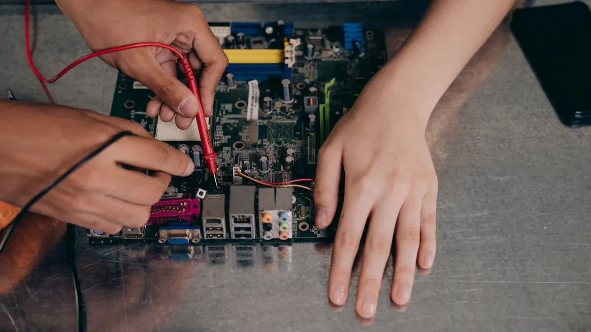
Electrical Testing with Multimeters
After looking at the PCB, test it with a multimeter. A multimeter checks if the PCB parts work properly. It measures voltage, current, and resistance in the circuit.
Start by testing continuity to check if paths are connected. Set the multimeter to continuity mode and test the traces and solder joints. A beep means the connection is good. No beep means there’s a break in the circuit.
Next, measure voltage at important points. For example, check if IC power pins get the right voltage. Wrong readings might mean a bad power supply or broken parts. Use the multimeter to test resistors, capacitors, and diodes. Compare the readings with their specs to find problems.
Note: Turn off the power before testing resistance or continuity. This protects the multimeter and PCB from damage.
Signal Debugging Methods
Signal debugging finds problems that affect how the PCB works. It checks signals for noise, distortion, or interference.
An oscilloscope is the main tool for this. It shows signal waveforms so you can see how they behave. Connect the oscilloscope to the amplifier’s input and output points. Compare the waveforms you see with what they should look like. Strange spikes or dips mean there’s a problem.
A signal generator can send test signals into the circuit. This helps trace where the signal weakens or gets lost. For example, if the signal fades in one area, parts there might be broken.
You can also use a spectrum analyzer to find electromagnetic interference (EMI). EMI can mess up sensitive parts and ruin signal quality. Once you find the interference source, fix it by improving grounding or adding EMI filters.
Tip: Keep signal paths short and shielded to reduce interference during debugging.
Finding Loose or Broken Components
Loose or broken parts can harm your amplifier PCB’s performance. Finding these problems early stops more damage and keeps it working well. Start by looking closely at the board. Check for parts that are out of place, cracked, or detached. Use a magnifying glass or microscope to find tiny issues you might miss with your eyes.
You can also gently shake the board to find loose parts. If you hear a rattle, a part might not be attached well. Focus on solder joints too. Weak or broken solder can make parts come loose. Use a multimeter to test these connections. Set it to continuity mode to see if current flows through the joints. If not, fix it by re-soldering the joint.
Heat and physical hits often damage parts. Bulging or leaking capacitors and discolored resistors are signs of trouble. Replace damaged parts right away to stop bigger problems. Keeping extra parts ready helps you fix issues quickly and avoid delays.
Tip: Be gentle when checking the PCB to avoid causing new damage.
Checking Power Supply Stability
A steady power supply is key for your amplifier PCB to work well. Power problems like voltage changes, noise, or low current can cause poor performance. Checking the power supply ensures the board gets clean and stable power.
Start by using a multimeter to measure voltage at important spots on the board. Compare the numbers to what the design says they should be. If the voltage is too high or low, the regulator or power unit might be broken. Use the multimeter to check for broken connections in the power lines too.
For a closer look, use an oscilloscope. It shows voltage changes in real time. Look for spikes or dips, which mean noise or instability. Oscilloscopes and power analyzers are great for spotting these problems. They give detailed data to help you find the issue.
Testing power early in the design phase avoids expensive fixes later. Simulations and tests can catch problems before they hurt performance. During repairs, make sure the power supply gives enough current for the amplifier. Adding capacitors near power-hungry parts can smooth out spikes and keep things stable.
Note: Check the power supply often to keep it reliable and match design needs.
Advanced PCB Repair Techniques
Using Thermal Imaging to Find Hotspots
Thermal imaging helps find hot spots on PCBs. These hot spots often mean there are problems like broken parts or design mistakes. Finding these early can stop more damage and make your PCB last longer.
Thermal cameras detect heat from parts on the board. They show how heat spreads across the PCB. For example, if a resistor gets too hot because of too much current, the camera will show it as a bright spot. You can then check that area for problems.
Studies show thermal imaging works well in important fields like medicine and the military. It uses tools like ultrasonic waves and machine learning to find even small heat issues. This helps catch problems before they get worse.
Tip: Use thermal imaging during tests to check heat levels. This can save time and lower repair costs.
X-Ray Scans for Hidden Problems
X-ray scans are great for finding hidden PCB problems. As parts get smaller and closer together, regular checks can miss issues like bad solder joints. X-rays give a clear inside view, making it easier to spot these hidden problems.
This method works well for checking solder joints in Ball Grid Array (BGA) parts. It can find bubbles, gaps, or weak connections. For example, if a solder joint is not fully formed, the X-ray will show the problem clearly.
Feature | Details |
|---|---|
Effectiveness | Finds hidden solder joint problems, especially in BGAs. |
Benefits | Shows inside views of solder joints, spotting bubbles and weak areas. |
Limits | Needs special tools and works best for certain parts like BGAs and CSPs. |
X-rays also help with high-density PCBs where parts are tightly packed. They are useful for checking solder joints made of heavy materials that are hard to inspect otherwise.
Note: X-ray scans need special tools and skills. Use them for important debugging tasks where accuracy matters.
Checking Signals with Spectrum Analyzers
Signal checks are key for fixing amplifier PCBs. A spectrum analyzer looks at signal frequencies to find noise, distortion, or interference. This tool is helpful for fixing problems in sensitive parts like op-amps.
Start by connecting the analyzer to the amplifier’s input and output. Look at the frequency spectrum for unusual spikes. These spikes might mean electromagnetic interference (EMI). Once you find the interference source, fix it by improving grounding or adding EMI filters.
Signal checks also help improve PCB performance. By studying frequency response, you can make sure the amplifier works as it should. This improves signal quality and makes the board more reliable.
Tip: Keep signal paths short and shielded to reduce interference. This makes signal checks more accurate.
Replacing Faulty Components
Fixing broken parts is an important step in amplifier PCB repair. Damaged pieces like capacitors, resistors, or transistors can mess up the circuit. Finding and replacing these parts helps the PCB work properly and stay reliable.
First, find the broken part. Use tools like a multimeter to check for unusual readings. For example, a capacitor that won’t hold a charge or a resistor with no connection is likely bad. Once you find the problem, carefully remove the part with a soldering iron. Heat the solder just enough to avoid harming nearby areas.
Choose a replacement part that matches the original one. Check details like resistance, capacitance, or voltage rating. Using the wrong part can cause more problems or even ruin the PCB. For instance, a capacitor with a lower voltage rating might fail during normal use.
After putting in the new part, check the solder joints. Make sure they are strong and neat. Weak solder joints can cause bad connections and performance issues. Test the circuit after replacing the part to ensure everything works well. This step confirms the repair was successful.
Tip: Handle parts gently. Use anti-static tools to avoid damage from static electricity.
Consulting Manufacturer Documentation
Manufacturer instructions are very helpful during PCB repairs. They give clear steps for handling, testing, and replacing parts. These guides often include diagrams, part details, and tips for fixing problems, making repairs easier and more accurate.
Follow industry rules like IPC 7711/21 for advice. This rule explains the best ways to fix and change electronic boards. Using these methods keeps the PCB working well and reliable. The table below shows key information:
Standard | Description |
|---|---|
IPC 7711/21 | Tips for fixing and changing electronic boards while keeping quality high. |
Manufacturer guides also help you pick the right replacement parts. They list approved parts and their details. This ensures you use parts that fit the design and won’t fail easily.
Note: Keep the instructions handy for later use. They save time and help avoid mistakes during repairs.
Preventive Tips for Amplifiers PCB
Best Practices for PCB Design
A good PCB design helps your amplifier work well. Keep signal paths short to avoid losing signals. Use a ground plane to reduce noise and make circuits stable. Place parts carefully to improve performance. For example, keep heat-sensitive parts away from power sources to stop overheating.
Check your design twice before making the PCB. Simulations can find problems early and save repair costs. Follow industry rules to make sure your PCB is safe and works properly.
Proper Soldering Techniques
Good soldering makes your PCB strong and reliable. Control solder heat and conveyor speed to avoid mistakes like short circuits. Studies show that fixing these settings lowers soldering problems and improves assembly quality.
Reflow soldering needs even heat to avoid weak joints. Uneven heat can cause problems that hurt the PCB’s durability. Use good tools and high-quality solder for better results.
Tip: Keep tools clean and move steadily to avoid soldering errors.
Ensuring Adequate Cooling and Ventilation
Cooling stops parts from overheating and breaking. Tools like SOLIDWORKS Flow Simulation show how cooling designs work. Simulations also prove that better heat sinks improve cooling.
Fans help move heat away faster.
Thermal checks find hot spots and improve reliability.
Add heat sinks, cooling fans, or thermal vias to keep the PCB cool. Watch the temperature often to keep it safe.
Regular Maintenance and Cleaning
To keep your amplifier PCB working well, clean it often. Dust, dirt, and moisture can build up and cause problems. Cleaning stops these issues and helps the board run smoothly.
First, check the board for dirt or rust. Use a soft brush or compressed air to remove loose dirt. For sticky grime, use isopropyl alcohol with a lint-free cloth or cotton swab. Don’t use water or strong chemicals, as they can harm the board. If there are connectors, clean them with contact cleaner to keep connections strong.
Maintenance also means checking for damage or wear. Look for burnt spots, loose solder joints, or discolored parts. Fix these problems quickly to avoid bigger issues. Tighten any loose screws to keep the board secure.
Store the PCB in a clean, dry place to make it last longer. Use anti-static bags to protect it from static electricity. Keep the temperature and humidity steady to avoid stress on the board.
Tip: Check and clean your PCB every few months to stop small problems from becoming big ones.
Using High-Quality Components
Using good-quality parts makes your amplifier PCB work better and last longer. Cheap parts often break under stress, causing more repairs. High-quality parts handle stress better and keep the board running smoothly.
Some parts, like power modules, CPUs, and Ethernet cards, fail more often. Choosing better versions of these parts makes the board more reliable. These parts can handle heat and stress without breaking.
Good parts also improve how fast and efficiently the PCB works. For example, a high-quality capacitor keeps voltage steady, and a strong resistor handles heat without damage.
Note: Good parts may cost more, but they save money by lasting longer and needing fewer repairs.
When buying parts, check their specs to make sure they fit your design. Avoid fake parts, as they don’t meet quality standards. Buy from trusted suppliers who sell certified parts.
Tip: Keep a list of reliable suppliers to get good parts for your PCB projects.
Amplifier PCB problems can harm how well it works. You now know how to find and fix issues like bad soldering, signal problems, and power troubles. Simple steps like looking at the board and testing parts make repairs easier. Good habits, like smart PCB design and cleaning often, stop problems before they start. Using these ideas keeps your circuit board strong and working well. By following these tips, you’ll get better at fixing PCBs and keep your amplifier in great shape.
FAQ
What tools are needed to fix amplifier PCBs?
You’ll need simple tools like a multimeter and soldering iron. For harder problems, use thermal cameras or spectrum analyzers. A magnifying glass or microscope helps spot tiny issues.
Tip: Begin with basic tools before trying advanced ones.
How can soldering mistakes be avoided?
Use good-quality solder and keep the heat steady. Don’t use too much solder to avoid bridges or weak joints. Clean your tools often for smooth work. Learn proper soldering to make strong connections.
Note: Always check solder joints after finishing your work.
Why is grounding important in PCB design?
Grounding keeps signals clear and reduces noise. Without it, signals can get messy or distorted. A ground plane links all parts, stopping interference and making the PCB stable.
Tip: Add a ground plane to improve how your PCB works.
How do you find overheating parts?
Check for burnt smells, swelling, or discoloration. A thermal camera shows hot areas on the board. Overheating usually happens in resistors, capacitors, or transistors. Replace bad parts quickly to stop more damage.
Note: Regular heat checks help avoid overheating problems.
Why use high-quality components?
Good parts last longer and work better under stress. They lower the chance of breaking and needing repairs. Certified parts give better performance and save money over time.
Tip: Buy parts from trusted sellers to avoid fake ones.