JTAG works by allowing you to test and fix circuit boards without physically touching them. You can quickly find problems, even on crowded boards, thanks to how JTAG works. It uses only a few pins and does not interrupt normal operations, making testing easy and unobtrusive for the device. You benefit from quick debugging and fast firmware updates. As technology advances, JTAG works to help you adapt to new devices and regulations, making your work easier and more reliable.
Key Takeaways
JTAG lets you test and fix circuit boards without touching them. This makes testing easy and does not get in the way.
Boundary-scan testing with JTAG finds problems with soldering and broken wires on busy PCBs.
You can use JTAG to program devices and update firmware right on the board. This saves time and helps stop mistakes.
JTAG works with systems that have more than one core. It lets you test and fix many cores at the same time.
Using JTAG helps you find more problems, often over 90%. This makes JTAG a good and trusted way to test electronics today.
What Is JTAG?
JTAG Interface Basics
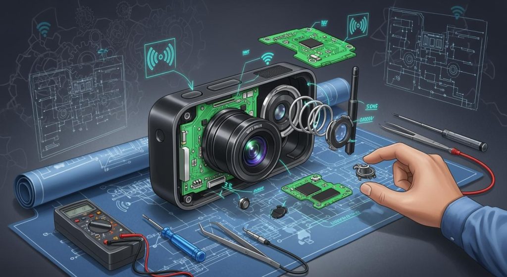
You use the jtag interface to connect your test equipment to a circuit board. This connection lets you talk directly to chips on the board. You do not need to touch the board with probes or needles. The jtag interface works by sending signals through a few dedicated pins. You can control and observe the inner workings of your device. This method helps you find problems quickly and safely.
JTAG gives you several important functions when you test and debug a PCB:
Boundary-scan testing helps you spot soldering issues, shorts, or broken connections.
You can debug embedded systems by interacting with the processor or memory.
In-system programming lets you upload firmware or software into chips.
You can observe registers and memory to monitor device health.
Fault detection helps you find manufacturing defects like shorts and opens.
Tip: You can use jtag to test boards even when you cannot reach every pin or trace. This makes it perfect for modern, complex PCBs.
Standard Pinout and Protocol
The jtag interface uses a simple pinout. You usually see five main pins:
Pin Name | Function |
|---|---|
TDI | Test Data In |
TDO | Test Data Out |
TCK | Test Clock |
TMS | Test Mode Select |
TRST | Test Reset (optional) |
You connect these pins from your test tool to the device. The jtag protocol sends data in a serial fashion. You shift test data into the device, and you read results back out. This process lets you check connections, program chips, and debug systems without extra hardware.
JTAG makes your job easier. You save time, reduce errors, and improve reliability. You can trust jtag to help you with testing and debugging every step of the way.
How JTAG Works for PCB Testing
Boundary Scan Method
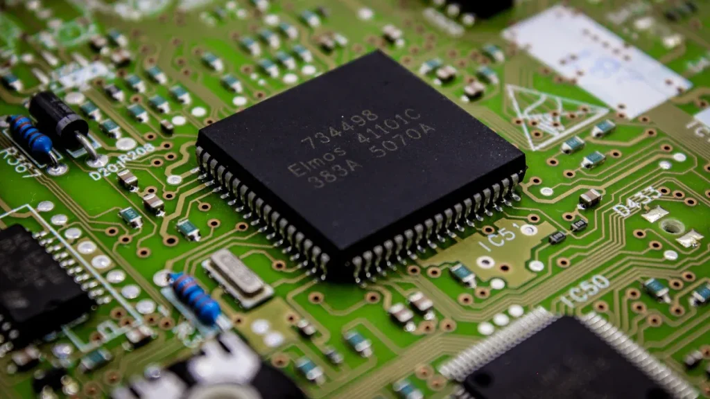
The boundary scan method lets you test a PCB without touching every pin. JTAG puts special shift-register cells at each input and output pin. These are called boundary scan cells. You move test data through the device one bit at a time. The Test Access Port and Boundary Scan Register help you control this. This setup lets you check connections and run tests on crowded boards.
Boundary scan testing helps you:
Test chip connections without using probes.
Find short circuits and open circuits at each pin.
Switch between normal and test mode without hurting the device.
Run tests on packed PCBs where other systems cannot reach.
You use JTAG by moving test patterns into the boundary scan cells. The cells send signals to the pins and catch the answers. This helps you find missing pull resistors or short circuits. You do not need extra hardware, so your job is faster and easier.
Digital Interconnection Testing
JTAG testing helps you check digital connections between parts. You can use it to make sure every signal path works right. JTAG sends test data through the scan chain and reads what comes back. If the answer is wrong, there is a problem with the connection.
You get many benefits:
You can find short circuits, solder shorts, and missing parts.
You can check for wrong or backwards parts that cause problems.
You can use test systems to check complex boards with many chips.
You can cover over 95% of standard faults.
Fault Type | Description |
|---|---|
Solder shorts | Happen when pins or traces touch because of too much solder. |
Open connections | Happen when there is not enough solder, broken joints, or broken traces, so signals cannot get through. |
Stuck-at faults | Happen when a net is always high or low, often from shorts to power or ground. |
Missing components | Show up as open connections on all pins of the device. |
Wrong or reversed components | Can cause strange behavior during interconnect testing. |
JTAG testing finds many types of faults. You can use it on boards that old test methods cannot handle. You do not need a bed-of-nails fixture or flying probe testers. JTAG is great for modern, high-density PCBs.
Fault Detection and Coverage
You want to find as many faults as you can. JTAG finds pin-level problems like short circuits, bridging, and wrong parts. Fault coverage is the percent of faults your test can find. With JTAG, you often get over 90% fault coverage if you design your board for testing.
JTAG finds short circuits, open circuits, and stuck-at faults.
You can use fewer test patterns, saving 20-50%, with only a small area needed for test points.
You can run tests fast and easily with test systems.
JTAG testing is better than old methods. Bed-of-nails and flying probe testers need to touch every node, which is hard on new boards. JTAG daisy-chains devices, so you can test many chips at once. You save time and make your work more reliable.
Note: JTAG cannot find every fault, especially in analog circuits or non-JTAG parts. You often use JTAG with other test systems, like in-circuit testing or automated optical inspection, to get the best results.
Many companies have made their testing better with JTAG. For example, IMSAR can find bad parts in minutes, not hours. Fibre Optic Equipment Specialists have cut test time using JTAG. These real examples show how JTAG helps make electronics manufacturing faster and more reliable.
JTAG Uses in Debugging and Programming
Debugging Embedded Systems
JTAG makes it much easier to debug embedded systems. With JTAG enabled devices, you can watch and control the processor as it works. You can start and stop the code whenever you want. You can also go through the code one step at a time. This helps you find bugs fast. You can set breakpoints to pause the code. You can also see how your code changes memory or registers.
Here is a table that shows what JTAG can do for debugging embedded systems:
Application Type | Description |
|---|---|
Hardware Testing | Lets you check devices, boards, and systems for problems. |
Software Debugging | Lets you debug code at the instruction or source level. |
Programming Devices | Lets you load firmware and set up bootloaders while developing. |
In-Circuit Debugging | Gives you access to microcontrollers, FPGAs, and SoCs for real-time debugging. |
Boundary-Scan Testing | Checks PCB connections and finds problems from making the board. |
Non-Intrusive Monitoring | Lets you watch CPU and memory without taking apart the board. |
You get direct access to the inside debugging parts of JTAG enabled devices. This means you can debug many kinds of processors and systems. You can also use JTAG for in-circuit debugging. This helps you fix problems while the device is still running.
Tip: With JTAG, you do not have to remove chips or use extra probes to test or debug embedded systems.
Device Programming
JTAG makes programming devices easy and dependable. You can use JTAG to load firmware, set up bootloaders, and update software on JTAG enabled devices. JTAG uses boundary scan, so you can program chips after they are soldered to the board. This saves time and helps you avoid mistakes during testing.
Many companies use JTAG for device programming because it works with many tools and frameworks. You can find cheap debug tools that use JTAG. This makes it easy to learn about device programming in schools and labs. JTAG enabled devices let you update code and fix bugs without taking parts off the board.
You can program flash memory and microcontrollers.
You can update firmware on FPGAs and SoCs.
You can reprogram devices after they are made.
Multi-Core System Support
JTAG helps you test and debug systems with more than one core. You can connect to many JTAG enabled devices in a chain and control each one. This lets you test how the cores work together. You can also debug each core by itself or all at the same time.
You use JTAG to:
Test connections between cores.
Debug software running on different cores.
Program each core with new code.
JTAG gives you a strong way to manage complex systems. You can find faults, update software, and make sure every part works right. This makes testing and debugging faster and more complete.
JTAG Architecture
Test Access Port (TAP)
The Test Access Port, or TAP, is the main entry for jtag work. TAP links your test tools to the inside of a device. It lets you send and get data for testing and fixing problems. TAP uses only a few pins, so you do not need many wires. This makes your setup easy and strong.
Here is a table that shows what TAP does in jtag:
Feature | Description |
|---|---|
Interface | TAP connects outside test tools to inside test logic. |
Control Mechanism | TAP uses a state machine to move data and control actions. |
State Management | The TAP controller works with a 16-state machine to handle tasks. |
Data Path Separation | TAP has separate paths for instructions and data, so you can pick what to test. |
TAP lets you control how data goes in and out of the device. It keeps instruction and data paths apart, so you can run special tests.
TAP Controller
The TAP controller is like the brain of the jtag system. You use it to run all jtag jobs. The TAP controller is a digital part that reads signals from TMS and TCK pins. It chooses what to do next by using a 16-state machine.
The TAP controller is a state machine. The TMS signal controls how it moves between states. Each state has two ways out, so TMS can guide every change when TCK is used.
You can use the TAP controller to switch between instruction and data modes. It lets you put in new instructions or move test data through the device. The TAP controller also helps you work with different registers for testing and programming.
Registers and Instruction Decoder
Every jtag device has some important registers inside. The Instruction Register (IR) holds the command the device uses now. Data Registers (DRs) keep test data, boundary scan info, or device IDs. The instruction decoder reads the IR and picks which register to use.
You can put new instructions into the IR to change what the device does. The instruction decoder then picks the right data register for your job. This way, you can test, program, or fix the device in a few easy steps.
You control how data and instructions move.
You can pick special tests or programming jobs.
You get quick and easy access to the inside of the device.
The jtag setup gives you a strong way to handle hard testing and fixing jobs. You can count on it to help you work faster and find problems easily.
JTAG vs. Related Standards
IJTAG Overview
You may see IJTAG when you work with advanced PCB testing. IJTAG stands for Internal JTAG. It builds on the original jtag standard. IJTAG helps you test chips, boards, and even whole systems. You can use IJTAG to connect many IP blocks inside a chip. This makes plug-and-play testing easier. IJTAG uses a Test Access Port to reach embedded instruments. You get more control and faster access to test features. IJTAG also uses standardized methods, so you can test different devices in the same way.
Here is a table that shows how JTAG and IJTAG compare:
Feature | JTAG | IJTAG |
|---|---|---|
Integration of IP blocks | Limited | Enhanced with plug-and-play |
Access to embedded instruments | Basic access | Easier access through TAP |
Standardization of methods | Not standardized | Standardized for uniform access |
Testing capabilities | Primarily board-level | Chip, board, and system testing |
Adoption | Established | Rapidly gaining traction |
CJTAG Overview
You may also hear about CJTAG. CJTAG stands for Compact JTAG. It is a smaller version of the jtag standard. CJTAG uses fewer pins and less power. You can use CJTAG for small chips and low-power devices. CJTAG works well for mobile devices and wearables. You still get strong testing features, but you save space and energy. CJTAG helps you test devices that cannot use the full jtag setup.
Unique Features
You get special features when you use jtag for testing and debugging:
You can use boundary-scan to test connections without touching pins.
You can test Ball Grid Array packages, which are hard to check by sight.
You only need a four-pin Test Access Port for jtag operations. Other standards may need more pins or extra hardware.
Tip: You can use jtag to test and debug many types of boards and chips. You do not need big test setups or special probes.
You can choose the right standard for your project. JTAG, IJTAG, and CJTAG each give you strong testing options. You can make your work faster and more reliable.
You use JTAG because it makes testing and fixing PCBs easier. JTAG lets you test, debug, and program devices right on the board. You do not have to take them off.
Functionality | Description |
|---|---|
Testing of Electronic Devices | Checks if things work right when they are made. |
Debugging Embedded Systems | Helps you find and fix problems in hardware or software. |
In-system Programming | Lets you update firmware while the device stays on the board. |
Boundary Scan Testing | Finds hard-to-see problems like open circuits and shorts. |
JTAG gives you a simple way to reach hardware and software. You can use JTAG on many different devices. This saves time and helps you make fewer mistakes. New tools, like JTAG ProVision, make testing even simpler. They help with new trends, like making things smaller and using more robots. JTAG keeps up with what modern design and factories need. You can count on it to help you.
FAQ
What does JTAG stand for?
JTAG stands for Joint Test Action Group. You use it as a standard way to test and debug electronic circuits.
Can you use JTAG on any PCB?
You can use JTAG only if the board and its chips support it. Most modern digital devices include JTAG, but some older or analog parts do not.
Why should you choose JTAG over traditional testing?
You save time and avoid extra hardware. JTAG lets you test, program, and debug without touching every pin. You get better fault coverage on complex boards.
Is JTAG safe for your devices?
Yes! JTAG works without interfering with normal device operation. You do not risk damaging the board during testing or programming.