You will notice important differences between inverting and non-inverting op-amp setups in how you connect the inputs and how the output acts. There are also differences in the phase of the output, the gain formula, and the input impedance each setup gives. You should know these main differences to make good design choices. These differences will change how your circuit works and how you plan your PCB design. This inverting vs non-inverting op-amp comparison helps you pick the best setup for your project.
Key Takeaways
Inverting op-amps turn the input signal upside down, but non-inverting op-amps keep it the same way. You should use inverting op-amps when you want to mix signals. Non-inverting op-amps are better for buffering and when you need high input impedance. Non-inverting op-amps usually make less noise, so they work well for sensitive jobs. Always look at the gain formulas. Inverting op-amps use Gain = -R2/R1. Non-inverting op-amps use Gain = 1 + (R2/R1). Good PCB design is very important. Keep traces short and keep analog and digital parts apart to lower noise.
Op-Amp Basics
What Is an Op-Amp?
You see op-amp a lot in electronics. An op-amp is a special amplifier. It makes voltage signals stronger. You use it in many kinds of circuits. It can do different jobs. The op-amp has two input pins. It also has one output pin. You put signals into the inputs. The op-amp gives you a stronger output signal.
The main idea is that an op-amp uses feedback. Feedback means some output goes back to the input. This keeps the op-amp steady and correct. Most of the time, you use negative feedback. Negative feedback stops the output from getting too big or wild. There is another rule called virtual short. This means both input pins have almost the same voltage. The op-amp does not take current from your signal source. Because of these things, you can use an op-amp for math jobs. It can add, subtract, integrate, and differentiate signals.
Key Characteristics
When you choose an operational amplifier, look at its main features. These features decide how your circuit works. Here is a table with the most important characteristics of an op-amp:
Characteristic | Ideal Value | Real Value Range | Implication on Circuit Performance |
|---|---|---|---|
Open Loop Gain (Avo) | ∞ | 20,000 to 200,000 | Makes the input signal bigger. More gain can help but may cause problems. |
Input Impedance (Zin) | ∞ | Few picoamps to several milliamps | High input impedance stops loading. This helps signals stay correct. |
Output Impedance (Vout) | 0 | 100Ω to 20kΩ | Low output impedance lets more current go to the load. This stops voltage from dropping. |
Bandwidth (BW) | ∞ | Limited by Gain-Bandwidth product | Wide bandwidth lets the op-amp work with many frequencies. This is important for AC signals. |
Offset Voltage (Vin) | 0 | Some output offset voltage | Small offset voltage is good for precision. It helps the output stay correct. |
Tip: Always check these values in the datasheet before you use an op-amp. Picking the right operational amplifier helps your circuit work its best.
Inverting vs Non-Inverting Op-Amp Comparison
Input and Output
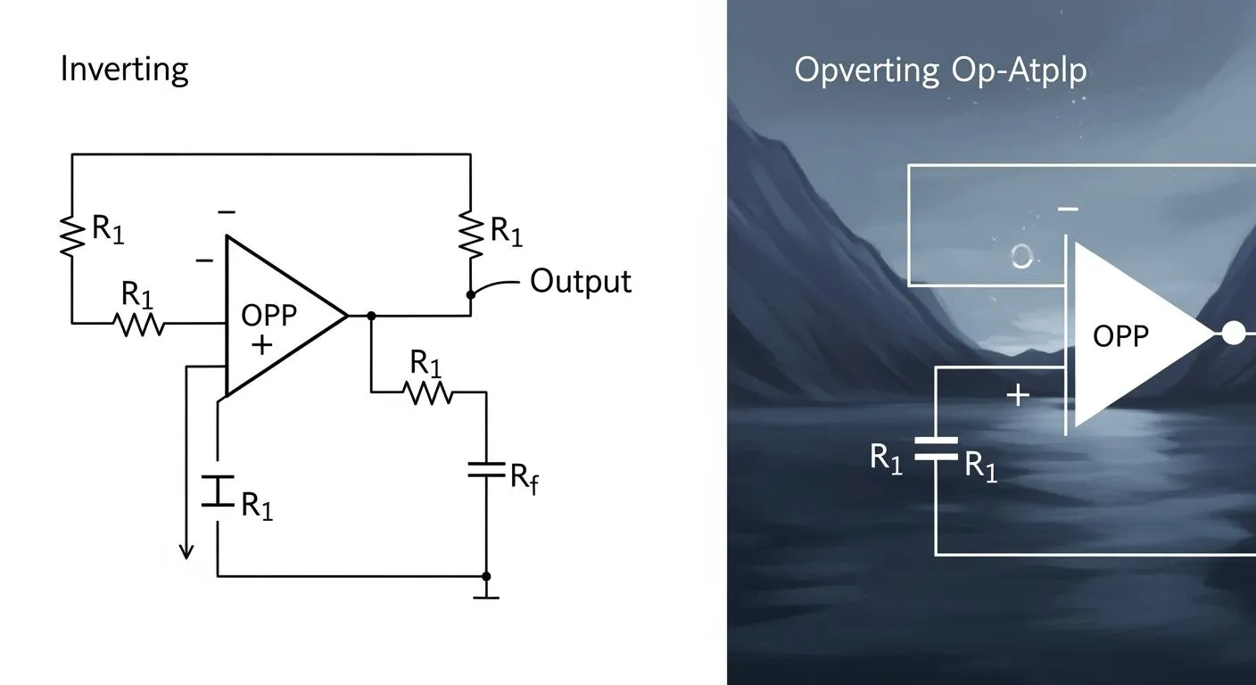
When you compare inverting and non-inverting op-amps, you see they connect differently. For an inverting op-amp, the signal goes to the negative input. The positive input usually connects to ground. The output comes out flipped compared to the input. For a non-inverting op-amp, the signal goes to the positive input. The negative input connects to a feedback network or voltage divider. The output matches the input and does not flip.
You use an inverting op-amp when you want to reverse the signal. You use a non-inverting op-amp when you want the output to stay the same as the input phase. Checking how the input and output connect is the first step in comparing these two types.
Phase and Gain
The phase of the output is very important. In an inverting op-amp, the output is 180 degrees out of phase with the input. If the input goes up, the output goes down. In a non-inverting op-amp, the output stays in phase with the input. When the input goes up, the output also goes up.
You should know the gain formulas for each type. Gain tells you how much the op-amp makes your signal bigger. Here is a table that shows the gain formulas for both:
Configuration | Gain Formula |
|---|---|
Inverting Amplifier | Gain = -R2/R1 |
Non-Inverting Amplifier | Gain = 1 + (R2/R1) |
The inverting op-amp gives a negative gain. The non-inverting op-amp gives a positive gain that is always at least one. Both can give high gain, but the resistor setup changes the result.
Impedance and CMRR
Impedance is another key difference. In an inverting op-amp, the input impedance comes from the resistor at the input. This value is usually not very high. In a non-inverting op-amp, the input impedance is much higher. It is almost infinite because it depends on the op-amp itself. High input impedance is good because it does not load the signal source.
CMRR means Common-Mode Rejection Ratio. It shows how well the op-amp ignores signals that are the same on both inputs. Both types can have high CMRR, but the non-inverting op-amp often does better in real circuits. This helps you get cleaner signals, especially when you need high gain.
Noise and Voltage Follower
Noise can make signals messy. Inverting op-amps pick up more noise. This happens because the input current goes through resistors and adds extra noise. Non-inverting op-amps usually have less noise. The feedback setup helps keep noise low, especially with low gain.
Here is a table that compares noise performance:
Configuration | Noise Performance |
|---|---|
Non-Inverting | Usually has lower noise because of feedback. |
Inverting | Picks up more noise from input current through resistors. |
Noise Gain | Non-inverting amplifiers can have lower noise gain at low closed-loop gains than inverting amplifiers. |
A non-inverting op-amp can work as a voltage follower. This means the output copies the input exactly. You use a voltage follower to connect different parts of a circuit without losing signal quality. Here are some things a voltage follower does:
Keeps parts of a circuit separate.
Maintains signal quality and matches impedance.
Has a voltage gain of 1, so output matches input.
Protects signal quality between circuit stages.
High input impedance means it draws little current.
Low output impedance lets it drive other circuit stages well.
An inverting op-amp cannot be a voltage follower. Only the non-inverting op-amp can do this job.
Applications Overview
You use both types in many projects. The inverting op-amp works well for mixing signals or making active filters. The non-inverting op-amp is better for high input impedance or buffering a signal. Here is a table that shows common uses for each type:
Application Type | Description |
|---|---|
Audio Amplifiers | Makes audio signals louder for better sound in devices. |
Summing Amplifiers | Combines many input signals into one output. |
Active Filters | Filters certain frequencies in signals. |
Instrumentation Amplifiers | Gives high precision and stability for measuring signals in instruments. |
You see these op-amp types everywhere in electronics. You pick the right one based on what your circuit needs. If you want high gain, you can use either type, but you must check phase, impedance, and noise. The inverting op-amp is great for mixing and filtering. The non-inverting op-amp is best for buffering and high input impedance.
Quick Reference Table
Here is a summary table for comparing inverting and non-inverting op-amps:
Feature | Inverting Op-Amp | Non-Inverting Op-Amp |
|---|---|---|
Input Connection | Negative input | Positive input |
Output Phase | 180° out of phase (inverted) | In phase (non-inverted) |
Gain Formula | Gain = -R2/R1 | Gain = 1 + (R2/R1) |
Input Impedance | Set by input resistor | Very high (almost infinite) |
CMRR | High | Higher in most cases |
Noise | More likely to pick up noise | Lower noise |
Voltage Follower | Not possible | Possible |
Applications | Mixing, filtering, summing | Buffering, high input Z, audio |
Now you know the main differences between inverting and non-inverting op-amps. This helps you choose the right one for your project, whether you need high gain, low noise, or special input and output features.
Op-Amp Inverting Amplifier
How It Works
You use an inverting amplifier when you want to flip your signal. The input signal goes through a resistor to the negative input. The positive input connects to ground. A feedback resistor links the output to the negative input. Here is how the signal moves in this circuit:
The input signal goes to the inverting input using a resistor.
The feedback resistor connects the output to the inverting input. This makes a negative feedback loop.
The current at the inverting terminal follows Ohm’s law.
This current also moves through the feedback resistor because of the virtual short.
The output voltage uses this formula: Vout = -Vin × (Rf / Rin). This shows the gain and the phase flip.
Technical Features
There are some important things about inverting amplifiers:
The gain uses the formula -Rf/Rin. You can set how much the signal grows by picking resistor values.
Input and output impedance change how the circuit works.
Noise can make your signal less clear.
The inverting amplifier uses negative feedback. This keeps the output steady and flipped.
If the op-amp bandwidth is too small, the circuit can become unstable. You can fix this with frequency compensation.
Pros and Cons
Advantages of Inverting Operational Amplifier | Disadvantages of Inverting Operational Amplifier |
|---|---|
More stable than non-inverting | Picks up more noise than non-inverting |
High gain possible by choosing resistors | Needs a more complex design |
Acts as a virtual ground, making design easier | Sensitive to input offset voltage |
Can flip the output phase | Common mode limits the input range |
High input impedance and low output impedance | Phase flip can be a problem in some circuits |
Applications
You see inverting amplifiers in many places. They are used in audio gear, control systems, and medical tools. The inverting amplifier is good for mixing signals, making filters, and adding signals together. You use this circuit when you need to control the phase or mix signals.
PCB Design Tips
When you make a PCB for an inverting amplifier, keep the traces short. This helps lower noise. Put resistors close to the op-amp pins. Use a solid ground plane for better stability. Keep input and output paths apart to stop unwanted feedback. Careful layout gives you the best results from your inverting amplifier.
Op-Amp Non-Inverting Amplifier
How It Works
You use a non-inverting amplifier when you want the output to match the input phase. The input signal connects to the positive terminal. The negative terminal connects to a voltage divider made with two resistors. This feedback path sets the gain. The output copies the input, so there is no phase flip. Non-inverting amplifiers are used when you need the signal direction to stay the same.
Technical Features
You can see how inverting and non-inverting amplifiers are different in this table:
Basis of Difference | Inverting Amplifier | Non-Inverting Amplifier |
|---|---|---|
Phase difference between input & output signals | 180° out of phase | In phase (0°) |
Input terminal configuration | Input at negative terminal | Input at positive terminal |
Feedback configuration | Feedback at same terminal as input | Feedback at different terminal |
Gain expression | $$A_v = -frac{R_2}{R_1}$$ | $$A_v = 1 + frac{R_2}{R_1}$$ |
Gain polarity | Negative | Positive |
Input impedance | Equal to R1 | Extremely high |
Applications | Trans-resistance amplifiers, integrator circuits | High input impedance circuits, voltage followers |
Pros and Cons
Non-inverting amplifiers have some good points. They also have some drawbacks. Here is a table that shows these:
Pros | Cons |
|---|---|
High input resistance | Slightly harder to design due to feedback setup |
Maintains original signal phase | |
Ideal for sensitive signals and buffers |
Applications
Non-inverting op-amps are used in sensor circuits and audio buffers. They are also used as voltage followers. These circuits need high input impedance and no phase change. You find non-inverting amplifiers in measurement tools and signal conditioning systems. They help protect weak signals and connect different circuit stages.
PCB Design Tips
Tip: Good PCB design helps your non-inverting amplifier work well and stay stable.
Put a bypass capacitor close to the op-amp supply pin to lower noise.
Check the open loop gain between output and input pins, because it limits your gain.
Use ways to get rid of heat in high power amplifier designs.
Keep analog and digital parts apart to stop noise from digital circuits.
Choosing the Right Op-Amp Configuration
Design Factors
You should think about a few things before picking an op-amp setup. Input impedance and gain are very important. The inverting setup gives gain using the feedback and input resistors. The non-inverting setup gives a little more gain because the formula adds one. This can cause problems if you do not check your resistor values. You need to make sure the gain fits what you want. Noise and phase also matter. The inverting op-amp flips the signal phase. The non-inverting op-amp keeps the phase the same. Think about how each setup changes your signal and stability. Good choices help your op-amp work well.
Tip: Always look at input impedance. The non-inverting op-amp has much higher input impedance. This helps keep weak signals safe.
Application Decisions
Different op-amp setups work best for different jobs. The table below shows which setup is good for each use:
Op-Amp Configuration | Key Features | Applications |
|---|---|---|
Differential Amplifier | Makes voltage difference bigger, blocks noise | Sensor measurements, instrumentation, high-precision analog circuits |
Voltage Follower | High input impedance, low output impedance | Sensor interfacing, data acquisition systems, stage isolation |
Pick the inverting op-amp when you need to mix signals or make filters. Use the non-inverting op-amp for buffering and keeping signals safe. Match the setup to your project for the best results.
PCB Impact
Your op-amp choice changes how you design your PCB. The inverting setup needs careful layout to keep noise low. Put resistors close to the op-amp pins. Keep traces short. The non-inverting setup lets you use longer traces because it has higher input impedance. Keep analog and digital parts apart to stop interference. Good PCB design helps your op-amp work well and makes building easier. Always plan your layout based on the op-amp setup you pick.
Design Tools and Best Practices
PCB Design Tools
You need good tools to build a strong op-amp circuit. Altium Designer has many helpful features. It works well for big, multi-layer PCB projects. Cadence Allegro helps with fast and RF designs. It checks if your signals are good. LTspice lets you test your op-amp circuit before you build it. These tools help you find problems early and fix your design. Using pro PCB software saves time and helps you avoid mistakes.
Circuit Optimization
You can make your op-amp circuit better by following easy steps:
Put clock signals on other layers than analog signals. This keeps noise away from your op-amp.
Use star grounding to stop digital noise from getting to analog parts.
Try differential signaling for analog inputs to block noise.
Pick the right parts. SMDs help lower extra inductance and capacitance.
Use microstrip or stripline layouts to keep signals clean.
Add heat sinks or thermal paths if your design gets hot.
Make sure your design is stable. Check input and output paths for oscillations.
Route power traces well so your op-amp gets clean voltage.
Keep analog and digital parts apart to lower interference.
Use a solid ground plane for a safe path for return currents.
Tip: Careful design choices help your op-amp circuit stay quiet and work well.
Assembly Collaboration
You get the best results when you work with your PCB assembly team. Good talking during design and assembly helps you avoid mistakes. If you share your design files early, the assembly team can check for problems like footprint mismatches. This teamwork can stop soldering issues and delays before they happen. When you talk with fabricators and assemblers, you make sure your design meets safety and quality needs. Working together helps you build a reliable op-amp circuit that fits your goals.
You have learned the main differences between inverting and non-inverting op-amps. The table below shows how each type changes phase, input, and what they are used for:
Feature | Inverting Op-Amp | Non-Inverting Op-Amp |
|---|---|---|
Phase Shift | 180-degree phase shift | 0-degree phase shift |
Input Configuration | Signal to inverting input | Signal to non-inverting input |
Input Impedance | Lower input impedance | High input impedance |
Applications | Inverting, summing amplifiers | Voltage followers, buffers |
Think about what you want your circuit to do. Do you need to make signals bigger, change them, or keep them the same? Figure out how much gain you need. Check what your circuit needs before you pick a setup. Use good PCB design tools. Follow smart steps to get the best results.
FAQ
What is the main difference between inverting and non-inverting op-amps?
For inverting op-amps, you put the input signal on the negative terminal. For non-inverting op-amps, you use the positive terminal for the input signal. The inverting type makes the output phase flip. The non-inverting type keeps the output phase the same as the input.
When should you use a voltage follower?
Use a voltage follower when you want to buffer a signal. This setup gives high input impedance and low output impedance. It helps protect weak signals. It also connects different circuit stages without losing signal strength.
Which configuration is better for low-noise applications?
Non-inverting op-amps give you lower noise. The feedback network in this setup helps keep noise down. For sensitive signals, pick the non-inverting configuration.
Tip: Make your PCB traces short. This helps lower noise even more.
How do you calculate the gain for each configuration?
Here is a quick reference table:
Configuration | Gain Formula |
|---|---|
Inverting Op-Amp | Gain = -R2 / R1 |
Non-Inverting Op-Amp | Gain = 1 + (R2 / R1) |
You choose resistor values to set the gain.