Decoding an amplifier circuit diagram is a useful skill. It helps you understand how electronic systems work. By learning this, you can fix problems easily. You can also create your own circuits from the beginning. For example, when you check parts, draw diagrams, and build on a breadboard, you learn by doing. This helps you find mistakes and check for correctness. These beginner skills connect ideas to real-life uses.
Start with simple circuits to practice. Practice often, and you’ll feel more confident. Over time, you’ll learn to handle any amplifier circuit easily.
Key Takeaways
Begin with easy circuits to gain confidence. Practice often to get better at reading and making amplifier diagrams.
Learn basic symbols for parts like resistors, capacitors, and transistors. Knowing these symbols helps you find parts in diagrams faster.
Understand how signals move through amplifier circuits. Spot the input, middle, and output stages to see how signals get stronger.
Use flashcards and tutorials to remember symbols and practice reading diagrams. Drawing circuits yourself helps you learn better.
Always stay safe when working with circuits. Use tools with insulation and discharge capacitors to avoid electric shocks.
Understanding Symbols in Amplifier Circuits
Common schematic symbols for resistors, capacitors, and transistors
When reading circuit diagrams, each part has its own symbol. These symbols make it easy to spot components in the circuit. Below are the most common ones you’ll see:
Resistors: Shown as a zigzag line or a rectangle. If it’s adjustable, an arrow crosses the symbol.
Capacitors: Non-polarized ones are two straight lines. Polarized ones have a curved line or a ‘+’ sign for polarity.
Transistors: Bipolar junction transistors (BJTs) have three parts: Base (B), Collector (C), and Emitter (E). Field-effect transistors (FETs) use Gate (G), Drain (D), and Source (S).
Tip: Be careful with capacitor and transistor symbols. Beginners often mix them up, causing mistakes in circuits.
How to read electrical schematics and recognize amplifier-specific symbols
Understanding schematics is easier when you know their layout. Amplifier circuits often include resistors, capacitors, transistors, and operational amplifiers. Operational amplifiers look like triangles with input and output points.
To read schematics:
Find the power and ground connections first. These are key to how the circuit works.
Locate the input and output points. Amplifiers take signals from the input and make them stronger at the output.
Follow the signal path through the parts. This shows how the circuit changes the signals.
Note: Symbols like operational amplifiers are important for understanding signal boosting. Learn these symbols to read amplifier diagrams better.
Tips for memorizing and interpreting schematic diagrams
Learning schematic symbols takes time, but simple tricks can help:
Group similar symbols: Sort symbols by type, like resistors, capacitors, and transistors. This helps you notice patterns.
Use flashcards: Write the symbol on one side and its name and job on the other. Review them often.
Practice with tutorials: Use step-by-step guides to study simple amplifier circuits. Tutorials with labeled diagrams help you learn faster.
Draw your own schematics: Drawing circuits helps you remember symbols and their uses.
Tip: Focus on what each part does in the circuit. This makes it easier to read diagrams and fix problems.
Signal Flow in Amplifier Circuits
Basics of signal flow: input, processing, and output
Knowing how signals move is important in amplifier circuits. Signals follow three steps: input, processing, and output. The input stage takes in signals like sound or voltage. The processing stage makes the signal stronger using parts like transistors or operational amplifiers. The output stage sends the stronger signal to a device, like a speaker.
For example:
In a comparator circuit, the input voltage is checked at the non-inverting terminal. The output changes to +15V or -15V based on the input’s direction.
In a non-inverting amplifier, a voltage divider sets the input voltage. The output copies the input voltage but has low impedance, making it good for powering devices.
How to trace signal paths in an amplifier circuit
Following the signal path is important for reading diagrams. First, find the input and output points on the schematic. Next, trace the connections between parts like resistors, capacitors, and transistors. See how the signal moves through each part of the circuit.
Watch for feedback loops, which are common in amplifiers. These loops send part of the output back to the input. This helps control or stabilize the signal strength. Knowing these loops helps you understand how the circuit works.
Tip: Use a marker or tool to highlight the signal path on the diagram. This makes it easier to follow complicated circuits.
Examples of signal flow in simple amplifier designs
Here’s a comparison of how signals move in two basic amplifier circuits:
Circuit Type | Input Description | Output Description |
|---|---|---|
Comparator Circuit | Checks input voltage at non-inverting | Outputs +15V or -15V based on input sign |
Non-Inverting Amplifier | Sets input voltage with a voltage divider | Outputs same voltage as input with low impedance |
These examples show how signals travel in different amplifier circuits. By studying these, you can learn to trace signal paths and understand how circuits work.
Note: Practice with easy diagrams and guides to get better at following signal flow.
Key Parts in Amplifier Circuit Study
Resistors: Controlling current and voltage
Resistors control how much current and voltage flow in circuits. They set the gain, which decides how much the signal is boosted. You can find the output voltage using this formula:VOUT = RGD × Gain × VSENSE / RG1.
Here’s how resistors work:
The ratio between resistors, like RGD and RG1, changes the gain. Manufacturers adjust these resistors for accuracy, even if they vary by ±30%.
To avoid gain errors, keep RSERIES+ small compared to RG1. Set RSERIES- to half of RSERIES+ to cancel offset voltage.
Resistors also protect parts by stopping too much current flow.
Knowing these ideas helps you see how resistors affect amplifier circuits.
Capacitors: Connecting and cleaning signals
Capacitors connect and clean signals in amplifier circuits. They let AC signals pass but block DC signals, keeping the circuit balanced. This helps keep the signal clear and strong.
The table below shows capacitor roles in different circuits:
Experiment Type | Capacitor Role in Signal Coupling and Filtering |
|---|---|
Single-stage transistor amps | Capacitors keep bias steady and let AC signals pass. |
Common-source amplifier | Capacitors keep bias stable and allow bigger signal gain. |
Capacitors also remove noise or interference. For example, they smooth out power supply voltage changes. Adding capacitors to your circuit makes signals cleaner and more stable.
Transistors: Boosting and switching signals
Transistors are key to amplifier circuits. They make weak signals stronger to power devices like speakers. A transistor has three parts: base, collector, and emitter. A small current at the base controls a bigger current between the collector and emitter.
Transistors can also act as switches in digital circuits. They turn signals on or off based on input voltage. In amplifiers, transistors work with resistors and capacitors to improve signal strength and quality.
Learning how transistors work helps you understand their role in diagrams and improves your circuit skills.
Other components and their roles in circuit analysis
When studying amplifier circuits, you’ll find more than resistors, capacitors, and transistors. These parts have special jobs that help the circuit work well.
Diodes: Letting current flow one way
Diodes let current move in one direction and block the other. They protect parts from voltage spikes in amplifier circuits. For example, diodes stop reverse current from harming transistors or operational amplifiers.
Inductors: Saving energy as magnetic fields
Inductors save energy as magnetic fields when current flows through them. They are rare in amplifier circuits but useful for high-frequency signals. Inductors can clean noise or steady voltage changes.
Operational Amplifiers: Making signals stronger
Operational amplifiers, or op-amps, look like triangles in diagrams. They make weak signals stronger and are key in many amplifier designs. You’ll see them in circuits like filters, comparators, and integrators.
Switches and Relays: Managing current flow
Switches and relays control current by opening or closing paths. Switches turn circuits on or off, while relays handle multiple signal routes. These parts make diagrams simpler and circuits more useful.
Connectors: Joining circuit parts
Connectors link different circuit parts together. They keep connections steady between components and devices like speakers or power supplies. Good connectors lower signal loss and improve performance.
Tip: Look at how these parts work together in diagrams. Knowing their jobs makes understanding even hard circuits easier.
Step-by-Step Guide to Reading Circuit Diagrams
Finding input, output, and key sections
When reading circuit diagrams, start by finding the input, output, and key sections. These parts show how the circuit works and its main purpose.
Input Section: Signals enter here. Look for parts like connectors, sensors, or input terminals. In amplifier circuits, this section often has resistors and capacitors to prepare signals for processing.
Output Section: Signals leave the circuit here. You’ll see parts like transistors or operational amplifiers that make signals stronger before sending them to devices like speakers.
Key Sections: These middle parts process signals. They include smaller circuits like voltage dividers, feedback loops, and filters. Each section has a job, like improving signal quality or keeping it steady.
Tip: Use guides or tutorials to learn about common circuit sections. Practice often to quickly spot these parts in diagrams.
Following signal paths and their jobs
Following signal paths helps you understand how parts connect in a circuit. Signals move through lines called traces that link components together.
Signal Lines: These carry signals through the circuit. Follow them to see how signals interact with resistors, capacitors, and transistors.
Power Lines: These bring energy to the circuit. Find the power source and follow its path to check if all parts get enough voltage.
Ground Lines: These connect parts to the ground. They stop interference and keep the circuit stable.
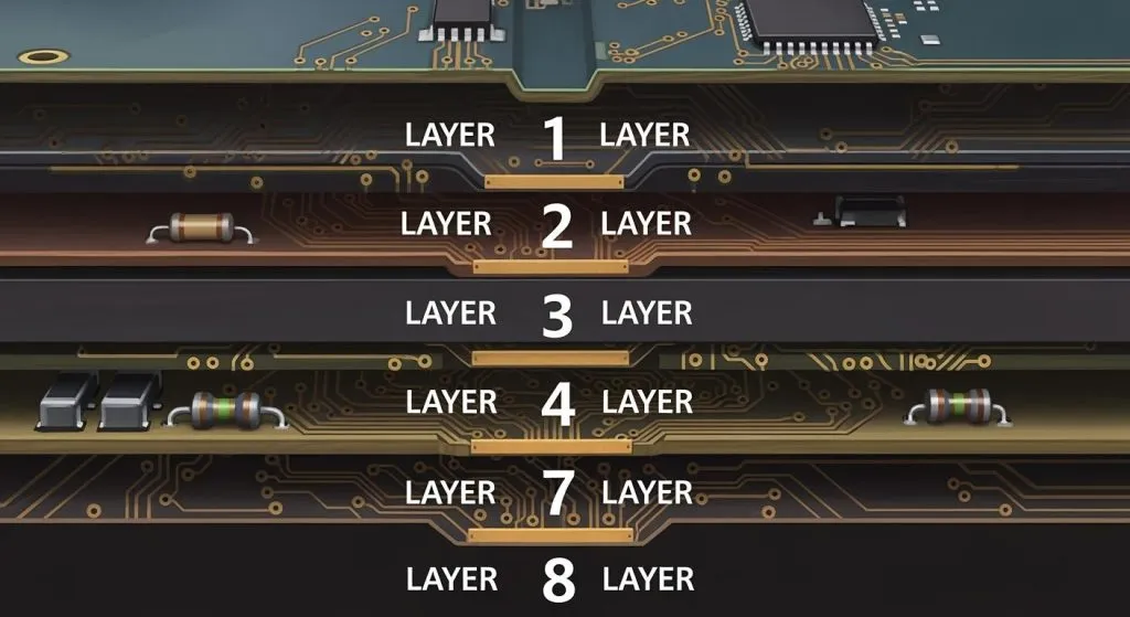
In complex circuits, you might see vias, which connect lines between layers in multi-layer boards. High-speed circuits often use special lines to keep signals clear.
To follow signal paths:
Start at the input and trace the signal through each part.
Look for feedback loops that send part of the output back to the input. These loops help control signal strength and keep the circuit steady.
Use standard symbols and layouts to understand the diagram better.
Note: Marking signal paths on the diagram can make it easier to follow, especially in detailed circuits.
Understanding what each part does
Every part in a circuit has a specific job. Knowing these jobs helps you understand how the circuit works and fix problems.
Resistors: These control current and voltage. They set the gain in amplifier circuits and protect parts by stopping too much current.
Capacitors: These connect signals and clean noise. They let AC signals pass but block DC signals, keeping signals clear.
Transistors: These make signals stronger and act as switches. A small current at the base controls a bigger current between the collector and emitter.
Diodes: These protect parts by letting current flow one way and blocking reverse currents.
Operational Amplifiers: These boost weak signals and are important in many amplifier designs. They look like triangles in diagrams.
Inductors: Rare in amplifier circuits, they store energy as magnetic fields and clean high-frequency noise.
For example, studies in medical engineering show how transistors and operational amplifiers improve circuit efficiency and power. These parts are tested to ensure reliable designs for devices like implants.
Tip: Use tutorials or reports to learn more about what each part does. Practice with simple circuits to get better at reading diagrams.
Recognizing feedback loops and their importance
Feedback loops are very important in amplifier circuits. They control how the circuit works by sending part of the output back to the input. This can make the circuit more stable or improve its performance, depending on the feedback type.
Types of Feedback Loops
Positive Feedback:
Positive feedback makes the input signal stronger. It increases the circuit’s gain, making the output bigger. But too much positive feedback can cause instability or oscillation. This type is often used in circuits that create specific frequencies, like oscillators.Negative Feedback:
Negative feedback weakens the input signal by using an inverted output. It makes the circuit stable and more accurate. It also lowers distortion and increases the amplifier’s bandwidth. Negative feedback is common in audio amplifiers for clear and steady sound.
How to Spot Feedback Loops in Circuit Diagrams
To find feedback loops in a diagram, follow these steps:
Look for lines connecting the output back to the input. These lines often go through parts like resistors or capacitors.
Check how the signal flows. Positive feedback sends the signal back in the same phase as the input. Negative feedback flips the signal.
Focus on operational amplifiers. These often use feedback loops to manage gain and stability.
Tip: Practice with simple diagrams to spot feedback loops faster. Start with basic amplifiers and move to harder designs over time.
Why Feedback Loops Are Important
Feedback loops greatly affect how amplifier circuits work. They control stability, gain, and efficiency. For example:
In audio amplifiers, negative feedback reduces distortion for better sound.
In control systems, feedback loops keep performance steady by adjusting output based on input changes.
In oscillators, positive feedback creates stable waveforms for communication or signals.
Knowing about feedback loops helps you understand and fix circuits better. It also lets you design circuits that work well by picking the right feedback type.
Note: Feedback loops are a key idea in electronics. To master them, study diagrams and practice often.
Safety Tips for Working with Amplifier Circuits
Understanding high voltage risks in amplifier circuits
Amplifier circuits can have high voltage, which is dangerous. Even small circuits might carry enough voltage to hurt you. Always assume a circuit is live unless you confirm it’s not. High voltage can cause shocks, burns, or even start fires.
To stay safe, don’t touch exposed wires or parts when the circuit is on. Use tools with insulation to handle components. Discharge capacitors before working on them. Capacitors can hold harmful energy even after the power is turned off.
Tip: Keep one hand in your pocket when working with high voltage. This lowers the risk of current passing through your chest if you touch something accidentally.
Essential tools and precautions for safe circuit analysis
Using the right tools makes working with circuits safer. A multimeter helps measure voltage, current, and resistance. Insulated screwdrivers prevent short circuits. A soldering iron with a grounded tip is safer for making connections.
Wear safety goggles to protect your eyes from sparks or flying debris. Work on a non-conductive mat to avoid accidental grounding. Keep a fire extinguisher close by for emergencies.
Before starting, check the circuit diagram to understand its layout. Make sure the power supply is off before touching any parts.
Note: Never work alone with high-voltage circuits. Having someone nearby can save your life in case of an accident.
Best practices for handling electrical components safely
Handle electrical parts carefully to avoid damage or injury. Hold components by their edges to prevent static electricity. Use an anti-static wrist strap for sensitive parts like transistors or chips.
Store parts in anti-static bags to keep them safe. Label wires and connections clearly to avoid mistakes. When testing circuits, start with low voltage and increase it slowly.
Keep your workspace tidy and free of clutter. Messy areas can cause short circuits or lost parts. Check your tools often to make sure they’re in good condition.
Tip: Always turn off the power and double-check connections before powering up a circuit. Small safety steps can stop big problems.
Understanding how to read schematic diagrams is an important skill. It helps you learn and fix circuits better. Start with simple amplifier circuits to practice and gain confidence. Drawing your own diagrams can also help you understand and remember better.
Use beginner-friendly books, online tutorials, or circuit simulators to learn more. These tools give clear steps and hands-on practice. Studies show that doing activities like these makes learning easier, especially for tricky ideas.
Keep practicing and treat every circuit as a chance to learn. Over time, you’ll get better at reading diagrams and designing or fixing circuits on your own.
FAQ
How can I start learning amplifier circuit diagrams?
Start with easy circuits. Learn basic symbols like resistors, capacitors, and transistors. Practice finding signal paths and input/output points. Use tutorials and simulators to test what you learn.
Tip: Drawing diagrams yourself helps you remember symbols and their jobs.
How do I avoid errors when reading schematics?
Check details like capacitor polarity and transistor connections. Mark signal paths to stay organized. Review feedback loops and power lines carefully.
Note: Mistakes happen when rushing. Take your time to study each part.
Are simulators useful for beginners?
Yes, simulators let you test circuits without real parts. They show how signals move and how components work together. Tools like LTspice or Tinkercad are great for beginners.
Emoji Tip: 🖥️ Simulators save time and help avoid costly mistakes in real circuits.
What if I don’t understand a circuit diagram?
Break it into smaller parts. Focus on one section, like the input or output. Search for unknown symbols or parts online. Ask for help in forums or guides.
Tip: Practice often to gain confidence and improve your skills.
Why are feedback loops important in amplifier circuits?
Feedback loops help control stability and gain. Negative feedback lowers distortion and improves accuracy. Positive feedback boosts signals but may cause instability.
Note: Knowing feedback loops helps you understand circuits and fix problems better.