IC power-supply pins let you deliver the right voltage and current to an integrated circuit. When you work with electronics, you need to know which pin connects to power and which one goes to ground. This knowledge helps you build safe devices and fix problems quickly. If you learn to spot the correct pin, you protect your circuit from damage and improve its performance.
Key Takeaways
Learn the main power-supply pins: VCC, VDD, VEE, VSS, and GND. Each pin has a special job to give voltage and current to your IC.
Always look at the datasheet for your IC. It gives important facts about what each pin does. This helps you avoid mistakes when you connect things.
Put bypass and bulk capacitors close to power pins. This makes your circuit more stable and cuts down on noise.
Find pin 1 on your IC the right way. Lining it up right keeps your circuit safe and working well.
Use good ways to set up I/O pins. This helps you control signals and makes your circuit work better.
Types of IC Power-Supply Pins
When you look at any power supply ic, you will see several types of pins that help the chip work correctly. Each pin has a special job. If you understand what each one does, you can make better choices in your circuit design and avoid mistakes.
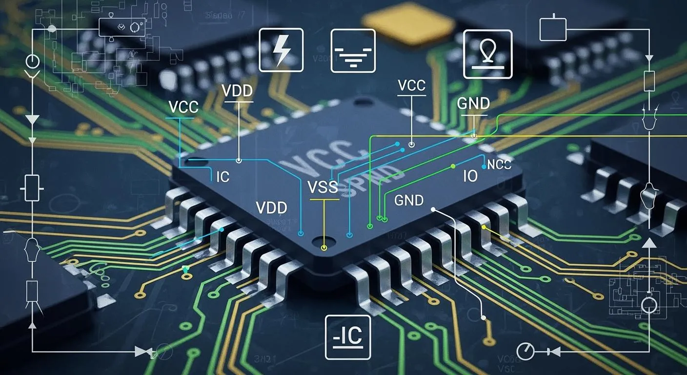
VCC, VDD, VEE, VSS, and GND
You will often see these five pins on many ICs. They help deliver the right voltage and current to the chip. Here is a table that explains what each pin does:
Pin | Definition and Function |
|---|---|
VCC | Positive power supply voltage for BJTs, enabling amplification and switching. |
VDD | Positive power supply voltage for FETs, controlling current flow and amplification. |
VEE | Negative power supply voltage for BJTs, ensuring proper conduction and biasing. |
VSS | Negative supply voltage for N-channel FETs, serving as a reference point for voltage levels. |
GND | Common reference point for all voltages in the circuit, ensuring stable operation. |
You will notice that VCC and VDD both provide positive voltage, but they work with different types of transistors. VEE and VSS usually give negative voltage or act as a reference. GND is the main ground pin. It keeps everything stable.
The way you use these pins can change depending on the type of IC. In digital ICs, you often use VDD as the main power supply and VSS as ground. In analog ICs, you might see both VCC and VEE to give the chip both positive and negative voltages. This setup lets the circuit handle signals that swing above and below ground. Here is a quick comparison:
Function | Digital ICs | Analog ICs |
|---|---|---|
Power Supply | VDD (single positive supply) | VCC (positive) and VEE (negative) for dual supply |
Ground Reference | VSS (ground) | VSS can be negative relative to ground |
Voltage Levels | Typically 0 V to VDD | Can swing from VEE to VCC |
Complexity | Simpler design with one rail | More complex with potential for dual supplies and separate analog/digital grounds |
Tip: Always check the datasheet for your power supply ic. The same pin name can mean different things in different chips.
VIO, VCAP, and Other Special Pins
Some ICs have extra pins for special jobs. You might see VIO, VCAP, or other names. These pins help the chip do more than just get power.
VIO: This pin gives power to the input/output (I/O) part of the chip. You use it when you want the I/O to run at a different voltage than the rest of the chip. This helps you connect the IC to other devices that use different voltages.
VCAP: This pin connects to a capacitor. The capacitor helps keep the voltage steady inside the chip. It can also help reduce noise and improve performance.
Other Special Pins: Some power supply ic chips have pins for things like standby power, analog reference, or even built-in regulators. Each one has a unique job that supports the main function of the chip.
You will find that ic power-supply pins do more than just bring power into the chip. They also help connect the inside of the IC to the outside world. Here are some ways these pins help your design:
Power-supply pins sit at the edges or corners of the chip. This keeps the path short and helps current flow better.
These pins lower unwanted effects like noise and signal loss.
They give the chip a direct link to your circuit’s power source.
They make sure each part of the chip gets the right voltage and current.
In complex designs, you might use more than one power rail. This lets you run different parts of the chip at different voltages for better performance.
Note: Good design starts with knowing what each pin does. If you connect the wrong pin, your circuit might not work or could even get damaged.
How IC Power-Supply Pins Work in DC-DC Circuits
Voltage and Current Supply
When you use a dc-dc circuit, you rely on the power-supply pins to deliver the right voltage and current to your IC. These pins act as the main entry points for energy. In a dc-dc converter, the IC changes one voltage level to another. You must connect the power pins correctly so the chip can handle the voltage and current it needs. If you supply too little voltage, the IC might not work. Too much voltage can damage the chip. The current must also match the needs of the circuit. If the current is too low, the IC may shut down or behave strangely.
You often see several power pins on a dc-dc IC. Each pin has a job. Some pins bring in the main voltage. Others help control the flow of current. You might find pins that sense the voltage to keep it steady. When you design a dc-dc circuit, always check the datasheet for the voltage and current ratings. This helps you avoid mistakes and keeps your circuit safe.
Tip: Always use the correct voltage and current for your dc-dc IC. This keeps your circuit running smoothly and protects your components.
Stability and Noise Control
Stability is key in any dc-dc circuit. You want the voltage to stay steady, even when the current changes. Noise can cause problems in your circuit. It can make the voltage jump or ripple. This can hurt the performance of your dc-dc converter.
You can improve stability and reduce noise by following good design steps:
Place bypass capacitors close to the power pins. These help filter out high-frequency noise.
Use bulk capacitors to keep the voltage steady during sudden changes in current.
Design your ground and power planes carefully. This helps manage noise, especially in circuits with high current switching.
Add decoupling capacitors near the IC power pins. These act as a shield against voltage spikes.
A stable power delivery network keeps your dc-dc circuit working well. You get clean voltage and steady current. This means your IC can do its job without errors.
Remember: Good layout and the right components help you control voltage and current. This leads to better power and less noise in your dc-dc circuits.
Identifying IC Power-Supply Pins
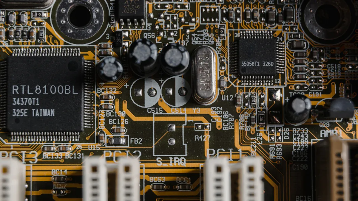
Pin Numbering and Markings
When you look at an IC, you see many input points called pins. Each pin has a number and a job. You must find the right input for power, ground, and other signals. Most ICs use special markings to help you find pin 1. You might see a notch, a dimple, or a chamfered edge. These markings show you where to start counting the input pins. Pin 1 is very important. If you connect the input pins in the wrong order, your circuit may not work.
Here are some common ways to spot pin 1 and other input pins:
A notch on the IC shows you that pin 1 is at the bottom left when the notch is on the left.
A small dimple marks pin 1 at the lower-left corner.
A chamfered edge also points to pin 1 at the lower-left corner.
Each input pin connects to a different part of the circuit, like power, ground, or signal input.
You should always check the coding system. Different regions use different codes. Here is a table that shows some common coding systems:
Coding System | Region | Description |
|---|---|---|
JEDEC | North America | Standard for IC codes. |
EIA/ECMA | Europe | Unique code assignment method. |
JIS-C-7012 | Japan | Separate coding structure for ICs. |
Identifying pin 1 helps you align the IC power-supply pins correctly. This step keeps your circuit safe and working.
Reading Datasheets and Pinouts
A datasheet is your best friend when you work with ICs. It tells you what each input pin does. You can find a pinout diagram in the datasheet. This diagram shows all the input pins, their numbers, and their functions. You can see which input is for power, which is for ground, and which is for signal input.
Datasheets often provide a block diagram that describes the internal configuration of the IC. From a block diagram, you can learn what functional blocks are provided inside the IC and what flow of events dictates the output. Also, along with the block diagram, it is common practice to provide descriptions of the operations of the functional blocks and the functions of individual pins, which constitute an important piece of information for the understanding of the operation of the IC.
When you read a datasheet, look for these things:
The total number of input pins on the IC.
The pinout diagram with each input pin labeled.
Color codes or symbols that make it easy to spot power and ground input pins.
Descriptions of each input pin’s job, like input, output, power, or reset.
You should always match the input pins on your IC to the layout on your circuit board. Make sure the input pins line up with the right spots. If you mix up the input pins, your circuit may not work or could get damaged. Always double-check the datasheet before you connect any input pin.
If you follow these steps, you can find and use ic power-supply pins with confidence. You will keep your circuit safe and make sure every input works as it should.
Power IC Pins: Functions and Best Practices
Special Functions (RT/CLK, FB, BOOT)
Some power ic pins do special jobs to help your circuit. These pins help with timing, feedback, and switching. The table below shows what RT/CLK, FB, and BOOT pins do:
Pin | Function Description |
|---|---|
RT/CLK | Sets how fast the oscillator works and can match up several DC-DC converters to lower input current ripple. |
FB | Is a feedback pin that keeps output voltage steady using a negative feedback loop. |
BOOT | Connects to a capacitor to give extra voltage to the gate of high-side FETs, so they work right even when SW voltage is high. |
Each pin does something special. RT/CLK lets you pick when switching happens. FB helps the IC check the output and change the input circuit to keep voltage steady. BOOT gives more voltage to the high-side switch’s gate, which helps with quick current changes and keeps output steady.
I/O Pins and Configuration
You need to set up I/O pins the right way for your IC to work well. How you set them up changes how the input circuit reacts to signals and current.
To make EMC better, do not leave unused clocks, counters, or I/Os open. Set I/Os to “0” or “1” (pull-up or pull-down on unused I/O pins) and turn off unused features.
Each I/O port has eight registers to control what it does.
PORTx registers let you read the logic levels on the pins.
Output Latch registers (LATx) let you write to the port and read changed values.
Tri-State Control registers (TRISx) set which way the pins go.
When you set up the input circuit, you pick the direction and logic for each pin. This helps you control current, voltage, and output for your project.
Common Issues and Solutions
Problems can happen if you do not connect power ic pins the right way. Here are some common problems and how to fix them:
Power rail collapse: Voltage drops if too much current is needed. Fix: Use power planes with low resistance and put bulk capacitors near power sources.
Ground bounce: Lots of ICs switching can make voltage spikes. Fix: Put ground vias close to power pins and use a solid ground plane.
Not enough decoupling: Bad capacitor placement causes noise. Fix: Put capacitors close to power pins and use different kinds for better decoupling.
Too much heat: High current makes things hot. Fix: Place parts for good airflow and use good thermal design.
Impedance mismatch: Makes voltage ripple and noise. Fix: Use solid power and ground planes and check impedance with simulations.
Bad grounding: Causes noise problems. Fix: Do not split ground planes and use lots of ground vias.
Bad part placement: Makes resistance and inductance go up. Fix: Keep related parts close and follow layout rules.
If you follow these tips, your input circuit will work better. You will keep voltage, current, and output steady. This helps your circuit last longer and work well.
Practical Examples and Troubleshooting
Correct vs. Incorrect Connections
You can avoid many problems by connecting ic power-supply pins the right way. If you make a mistake, your circuit might not work or could get damaged. The table below shows some common mistakes and how they affect your project:
Mistake Type | Description |
|---|---|
Insufficient Input Voltage | You connect a 12V DC adapter instead of the needed 14V–15V DC. The voltage is too low for proper regulation. |
Missing Required Capacitors | You skip the needed capacitors. The circuit may start to oscillate and the output becomes unstable. |
Incorrect Ground Connection | You use separate grounds for input and output. This causes grounding problems and can lead to noise. |
Reverse Polarity Connection | You swap the input and output pins. This can damage the IC or stop it from working. |
Tip: Always double-check each pin before you power up your circuit. Use the datasheet to match the pin numbers and names.
Real-World Scenarios
When you face issues with your circuit, you can follow simple steps to find and fix the problem. Here is a checklist you can use:
Gather your tools. You need a multimeter and an oscilloscope. Look for burnt parts or loose connections on the board.
Measure resistance to ground at important pins. This helps you find short circuits or open circuits.
Power on the circuit. Check the input voltage and look at the waveforms. This shows if the voltage is steady or if there are spikes.
Watch for common faults. If you see a blown fuse, no DC output, or weak load capacity, use these clues to guide your repair.
Note: Careful inspection and testing help you find problems with voltage or pin connections quickly.
If you follow these steps, you can solve most issues with ic power-supply pins. You will keep your circuit safe and make sure it works as planned.
You should learn about IC power-supply pins. This helps you make electronics that work well. If you connect the pins the right way, you stop many problems. Experts say good pins help with strong current and solid connections. They also keep your system stable. The table below explains why these pins are important:
Key Reason | Explanation |
|---|---|
High Current Capacity | Pins can carry lots of current and stay cool. |
Specialized Connectors | Power connectors keep the link strong. |
Reliability of Connections | Good pins help all parts work together. |
Stability of Electrical System | Quality pins stop signals from getting lost or mixed up. |
Consequences of Low-Quality Pins | Bad pins can break things or make signals weak. |
Knowing this helps you make safer projects. It also makes fixing things easier.
FAQ
What happens if you connect the wrong power-supply pin?
If you use the wrong pin, the IC can break or not work right. Always look at the datasheet before you connect anything. Picking the right pin keeps your circuit safe.
How do you find the power-supply pins on an IC?
Check for marks like notches or dots on the IC. The datasheet has a pinout picture to help you. Pin 1 is marked in a special way. Match the picture to your IC to find the right pins.
Why do some ICs have more than one power-supply pin?
Some ICs need different voltages for different parts inside. More power-supply pins let you run analog and digital parts at their own levels. This helps the chip work better and cuts down on noise.
Do you need to use capacitors with power-supply pins?
Benefit | Why Use Capacitors? |
|---|---|
Stability | Helps keep voltage steady |
Noise Reduction | Blocks signals you do not want |
You should put capacitors close to power pins for best results.