Flexible circuits, commonly known as flex circuits or flexible printed circuit boards (FPC), are crucial components in the world of electronics. Comprising a thin insulating polymer film with conductive patterns, these circuits are often coated for protection. Since their inception in the 1950s, flex circuits have evolved into a vital interconnection technology for advanced electronic products. Unlike traditional rigid PCBs, flexible PCBs are designed to bend, requiring specialized design rules—termed “flex-izing” by the Hemeixin team—to optimize their performance.
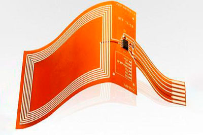
Typically made from polyimide base material, adhesive layers, and copper traces, flexible PCBs offer significant advantages in weight and assembly efficiency, making them suitable for a variety of applications despite a higher cost compared to rigid PCBs. Their versatility allows them to withstand diverse conditions, catering to industries such as consumer electronics, automotive, and medical devices. With the demand for miniaturized and integrated electronic solutions on the rise, flexible PCBs are increasingly favored for their unique properties and functionality.
Basic Types of Flexible PCB
Flexible printed circuits (FPC) are essential in applications where circuits need to wrap around or fit within compact spaces, like electronic devices. These circuits can be tailored based on specific mechanical, thermal, and chemical requirements. The primary types of flexible PCBs include:
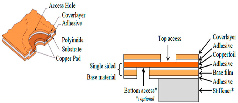
- Single-Sided Flexible PCB
- Comprising a single layer of conductive traces on one side of the dielectric substrate, single-sided flex circuits are ideal for straightforward applications. The key components include:
- Dielectric Substrate Film: Typically made of polyimide (PI), which offers high tensile strength and temperature resistance.
- Electrical Conductors: Copper traces that form the circuit’s pathways.
- Protective Finish: A cover lay or cover coat that shields the conductors.
- Adhesive Material: Often polyethylene or epoxy resin, used to bond the various components.
- Comprising a single layer of conductive traces on one side of the dielectric substrate, single-sided flex circuits are ideal for straightforward applications. The key components include:
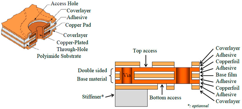
- Double-Sided Flexible PCB
- These circuits feature conductive traces on both sides of the substrate, allowing for more complex designs and increased functionality. The manufacturing process is similar to that of single-sided PCBs but includes additional steps for connecting the two sides, often using plated through holes (PTHs) for electrical connections.
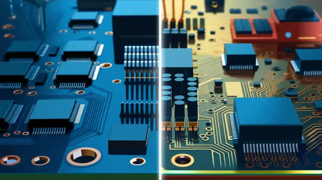
- Multi-Layer Flexible PCB
- Multi-layer FPCs incorporate multiple conductive layers separated by dielectric material, making them suitable for highly complex applications. The production technique mirrors that of double-sided FPCs, but it requires careful handling of PTHs to establish connections between layers. This structure enables the integration of multiple functionalities into a compact form factor. The adhesive layers also provide additional protection against moisture and contaminants.
Flexible PCB Stackup

Materials Used in Flexible PCBs
The unique capabilities of flexible printed circuits (FPCs) stem from their specialized materials and construction methods. Understanding these materials is crucial for achieving the desired performance and reliability in electronic applications. Here’s an overview of the key components that make up a flexible PCB:
1. Dielectric Flexible Substrate
The dielectric substrate serves as the foundational layer for the conductive traces. Selecting the right substrate material is essential, with common options including:
- Polyimide (Kapton): The most popular choice due to its high-temperature rating and excellent chemical resistance.
- Polyester (PET): A cost-effective alternative with a moderately high-temperature rating.
- Polyamide: Maintains flexibility even at low temperatures.
- Fluoropolymers (PTFE): Known for superior chemical resistance but at a higher cost.
- Liquid Crystal Polymer (LCP): Ideal for high-frequency applications with low signal loss.
Among these, polyimide is the most widely used due to its durability, thermal properties, and cost-effectiveness.
2. Copper Foil
An ultrathin rolled annealed copper foil is laminated onto the dielectric substrate. The typical thickness ranges from 12μm to 35μm (0.5 oz to 1 oz), with thinner options selected based on current-carrying requirements to enhance flexibility.
3. Conductors
Conductive paths or traces are created on the copper foil using lithographic processes. A subtractive method is commonly employed for fabricating the conductors.
4. Coverlay
A thin flexible dielectric coverlay is laminated over the conductor layer for insulation and protection. Coverlay thickness usually ranges from 25 to 50μm, with materials like Kapton or polyester being common choices.
5. Bonding Adhesive
Acrylic or epoxy-based adhesive films are utilized to bond the substrate with the copper foil and the coverlay. These adhesives provide strong adhesion while maintaining the flexibility of the circuit.
6. Stiffeners
In multilayer constructions, additional dielectric stiffening layers may be included to minimize wrinkling or buckling caused by thermal stresses.
7. Finish and Coatings
To insulate the conductor patterns and prevent oxidation, a solder mask is applied. Various surface finishes, such as hot air solder leveling (HASL), can also be employed to enhance performance.
Advantages and Disadvantages of Flexible PCBs
Flexible printed circuits (FPCs) offer a range of benefits and some drawbacks, making them suitable for various applications in the electronics industry. Understanding these pros and cons is essential for making informed design choices.
Advantages of Flexible PCBs
- Thin and Lightweight:
- FPCs typically range from 12 μm to 180 μm in thickness, allowing for extremely lightweight circuits. This characteristic is crucial for applications where space and weight are critical, such as in portable devices.
- Bend Radius:
- Flex PCBs can be bent to tight radii (down to 3 times their thickness) and can endure dynamic flexing up to 10 times their thickness, enhancing design flexibility.
- Heat Resistance:
- With polyimide substrates capable of withstanding temperatures up to 400°C, flexible PCBs can endure reflow soldering processes, making them suitable for high-temperature applications.
- Chemical Resistance:
- The substrates used in FPCs provide good resistance to common chemicals, enhancing durability during assembly and operation.
- High Frequency Performance:
- The short signal paths and thin dielectric layers facilitate excellent performance at high frequencies, especially when using substrates like LCP (Liquid Crystal Polymer).
- Reduced Wiring Costs:
- FPCs can replace traditional wiring methods, leading to reductions in assembly costs by up to 70%. This also minimizes human errors in wiring.
- Design Flexibility:
- Flexible PCBs can be designed in various configurations, including single-sided, double-sided, and multilayer options, accommodating complex electronic systems.
- Durability and Reliability:
- They are built to withstand continuous mechanical stress and vibrations, making them highly reliable in demanding environments, such as automotive applications.
- Improved Airflow and Thermal Management:
- The streamlined design of FPCs enhances thermal dissipation, allowing for better airflow and maintaining lower temperatures.
Disadvantages of Flexible PCBs
- High Initial Costs:
- The one-time design and prototyping costs for flexible PCBs can be significantly higher than those for traditional rigid PCBs. This makes them less suitable for low-volume production runs.
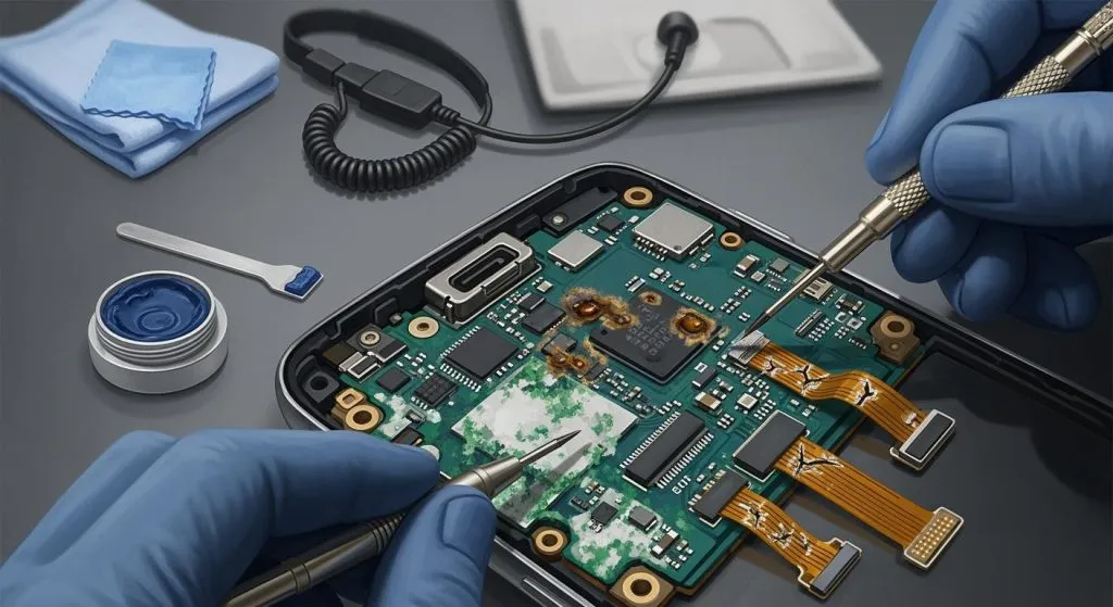
- Difficulty in Repair and Modification:
- If a flexible PCB requires rework, it can be challenging to remove the protective layers, perform repairs, and restore the circuit’s integrity.
- Handling Sensitivity:
- Flexible PCBs can be delicate, and improper handling during assembly can lead to damage. Care must be taken to ensure they are not mishandled by unauthorized personnel.
- Limited Availability:
- Not all manufacturers are equipped to produce flexible PCBs, which can limit sourcing options.
Applications of Flexible PCBs
Flexible printed circuits (FPCs) are integral to a wide range of technologies, from everyday consumer electronics to sophisticated aerospace components. Their adaptability and lightweight nature make them ideal for various applications across multiple industries. Here are some key areas where flexible PCBs are commonly used:
1. Communications
FPCs are crucial in telecommunications equipment, providing reliable connections in devices such as smartphones, tablets, and networking equipment. Their compact design allows for efficient signal transmission and minimized interference.
2. Consumer Electronics
Flexible circuits are widely used in consumer electronics, including cameras, calculators, and handheld gaming devices. Their ability to fit into small and intricate designs enables manufacturers to create slimmer and more functional products.
3. Automotive
In the automotive industry, flexible PCBs are employed in numerous applications, including:
- Airbag systems: Ensuring quick deployment during a collision.
- Engine controls: Managing various engine functions efficiently.
- Antilock brakes: Enhancing vehicle safety and performance.
- GPS systems: Providing navigation and location services.
Their resistance to vibrations and ability to operate in harsh environments make them particularly suitable for automotive applications.
4. Medical
Flexible PCBs are vital in medical devices such as heart monitors, pacemakers, and hearing aids. Their lightweight design and flexibility allow for intricate configurations that enhance device performance and patient comfort.
5. Industrial
In industrial applications, flexible circuits are used in motion systems and automation equipment. Their durability and resistance to environmental factors ensure reliable operation in demanding settings.
6. Aerospace
FPCs play a significant role in avionics and satellite systems, where reliability and performance are critical. Their lightweight nature helps reduce overall system weight, contributing to improved fuel efficiency and performance.
7. Military
Flexible circuits are used in various military applications, including communication devices and navigation systems. Their robustness and reliability in extreme conditions make them ideal for defense technologies.
8. Transportation
In transportation systems, flexible PCBs are utilized due to their enhanced resistance to vibrations and movement, making them suitable for trains, aircraft, and other vehicles.
Common Applications
Some of the most notable applications of flexible PCBs include:
- Battery packs
- Bar code equipment
- Printers
- Cameras
- Cell phones
- Fuel pumps
- Motion systems
- Satellites
The versatility and performance of flexible printed circuits enable their use in high-cycle flexing applications, where accuracy and reliability are paramount. As technology continues to evolve, the demand for flexible PCBs is expected to grow, further enhancing their role in the future of electronics.