1. Introduction
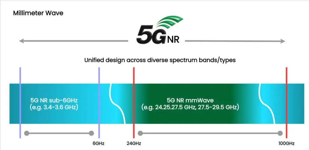
The success development of 5G PCB designs hinges critically on material selection. As 5G technology pushes frequencies into the millimeter-wave (mmWave) range of 24-77 GHz and beyond, traditional printed circuit board materials like standard FR-4 struggle to maintain signal integrity due to high dielectric loss and unreliable electrical properties. The selection of substrate material directly effects signal loss, thermal management, impedance control and reliability of 5G devices.
Three primary material families dominate the 5G PCB landscape: Rogers high-frequency laminates, PTFE (polytetrafluoroethylene)-based substrates, and LCP (Liquid Crystal Polymer) materials. Each family offers distinct advantages in terms of electrical performance, mechanical properties, processing requirements, and cost. Rogers’s materials strike a balance between performance and manufacturability, PTFE-based laminates deliver the lowest losses for demanding applications, while LCP enables flexibility without compromising RF performance.
2. Key Material Properties for 5G Applications
2.1 Dielectric Constant (Dk/εr)
The dielectric constant (Dk or εr) is an essential material property that determines how electromagnetic waves propagate through the substrate. It directly affects impedance control and signal propagation speed. Lower Dk values result in faster signal propagation and wider trace widths for a given impedance, which can simplify routing. However, lower Dk also means larger wavelengths, which can increase antenna sizes.
For 5G applications, typical Dk ranges are:
- Rogers materials: Dk 3.0-3.5 (RO3003 at 3.00, RO4350B at 3.48)
- PTFE-based laminates: Dk 2.1-2.2 (RT/duroid 5880 at 2.20)
- LCP substrates: Dk 2.9-3.2
Consistency of Dk across frequency and temperature is equally important. Materials with stable Dk minimize impedance variations and maintain signal integrity across the 5G spectrum.
2.2 Dissipation Factor (Df/Loss Tangent)
Dissipation factor (Df), also known as loss tangent (tan δ), quantifies dielectric loss in the substrate material. At high frequencies, even small differences in Df significantly impact signal attenuation. Lower Df values are critical for mmWave applications where insertion loss must be minimized to maintain acceptable link budgets.
Comparative Df values at 10 GHz:
- Rogers RO4350B: Df 0.0037 (good balance)
- Rogers RO3003: Df 0.0010 (ultra-low loss)
- PTFE (RT/duroid 5880): Df 0.0009 (lowest available)
- LCP: Df 0.002-0.004 (varies by formulation)
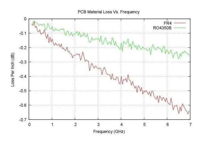
For mmWave frequencies (24-77 GHz), the choice of material can mean the difference between a functional and non-functional design. A material with Df = 0.0037 may lose 3-4 dB more than one with Df = 0.0009 over a 10 cm transmission line at 28 GHz.
3. Rogers High-Frequency Laminates
Rogers Corporation has developed a comprehensive portfolio of high-frequency laminates specifically engineered for RF and microwave applications. These materials have become industry standards for 5G PCB designs due to their excellent electrical performance, manufacturability using standard PCB processes, and competitive pricing compared to pure PTFE alternatives.
3.1 Rogers RO4000 Series (RO4350B, RO4003C)
The RO4000 series represents Rogers’ most popular material family, offering hydrocarbon/ceramic-filled laminates with glass reinforcement. These materials combine excellent electrical performance with FR-4 compatible processing, making them accessible to most PCB fabricators.
Key specifications for RO4350B (most widely used):
- Dielectric Constant: 3.48 ± 0.05 (at 10 GHz)
- Dissipation Factor: 0.0037 (at 10 GHz)
- Glass Transition Temperature: >280°C
The major processing advantage of RO4000 series is compatibility with standard FR-4 fabrication techniques—no special etching or plasma treatment required. This significantly reduces manufacturing costs and lead times. RO4350B can be drilled, routed, and plated using conventional processes.
3.2 Rogers RO3000 Series (RO3003, RO3006)
The RO3000 series targets applications requiring ultra-low loss performance. RO3003, with a dissipation factor of just 0.0010 at 10 GHz, rivals pure PTFE materials while maintaining better dimensional stability and lower cost.
These PTFE-ceramic composite materials offer:
- RO3003: Dk 3.00, Df 0.0010 (lowest loss in Rogers portfolio)
- RO3006: Dk 6.50, Df 0.0020 (higher Dk for compact designs)
- Stable electrical properties up to 77 GHz and beyond
- Low Z-axis CTE for reliable via performance
RO3000 series is ideal for 5G base station power amplifiers operating at 3.5 GHz and mmWave frequencies (24-40 GHz), phased array antennas, and millimeter-wave backhaul equipment.
3.3 Rogers RT/duroid Series
RT/duroid 5880 represents Rogers’ premium PTFE-based laminate, offering the lowest dielectric constant and dissipation factor in their portfolio. With Dk of 2.20 and Df of 0.0009 at 10 GHz, it competes directly with pure PTFE materials.
The material consists of pure PTFE with glass microfiber reinforcement, providing:
- Excellent electrical performance above 20 GHz
- Low moisture absorption (0.02%)
- Consistent performance from DC to 110 GHz
RT/duroid 5880 is the material of choice for mmWave phased array antennas (28 GHz, 39 GHz), satellite communications, aerospace radar systems, and high-performance 5G test equipment. Processing requires PTFE-specific handling including sodium etching or plasma treatment for copper bonding.
3.4 When to Choose Rogers
Select Rogers materials when you need a balanced performance-to-cost ratio. RO4000 series is optimal when standard PCB manufacturing capabilities are desired and frequency range extends from 500 MHz to 40 GHz. RO3000 series suits applications requiring ultra-low loss up to 77 GHz. RT/duroid is appropriate for the most demanding mmWave applications above 20 GHz. The broad frequency coverage of 500 MHz to 77 GHz makes Rogers materials versatile across the entire 5G spectrum.
4. POLYTETRAFLUOROETHYLENE PTFE-Based Laminates
Pure PTFE (polytetrafluoroethylene) and PTFE-based composite laminates represent the pinnacle of low-loss PCB materials. While more expensive and challenging to process than Rogers materials, PTFE offers unmatched electrical performance for the most demanding 5G applications, particularly in the mmWave spectrum above 40 GHz.
4.1 Pure PTFE Characteristics
PTFE’s molecular structure provides exceptional properties:
- Lowest dielectric loss: Df typically 0.0009-0.0012 across the entire RF spectrum
- Excellent frequency stability: Electrical properties remain constant from DC beyond 100 GHz
- Very low moisture absorption: <0.01%, preventing dielectric property degradation
These properties make PTFE ideal for applications where signal loss directly impacts system performance, such as long-range 5G backhaul links, mmWave radar systems, and precision test equipment.
4.4 PTFE Applications
PTFE materials excel in applications where low loss justifies the additional cost:
- Millimeter wave radar: Automotive 77-81 GHz radar for autonomous vehicles requires PTFE’s ultra-low loss to achieve detection ranges of 200+ meters.
- Satellite communications: Ka-band (26.5-40 GHz) and Ku-band (12-18 GHz) ground terminals and repeaters benefit from reduced signal loss.
- Test and measurement equipment: Network analyzers, spectrum analyzers, and calibration standards operating to 110 GHz require precision and stability.
4.5 When to Choose PTFE
Choose PTFE when ultimate low-loss performance is required, typically for frequencies above 40 GHz. Budget must accommodate premium material costs (4-8× FR-4) and specialized processing. Applications involving harsh environment operation—extreme temperatures, corrosive chemicals, or high humidity—also benefit from PTFE’s exceptional durability. For most sub-40 GHz 5G applications, Rogers materials provide sufficient performance at lower cost.
5. Liquid Crystal Polymer (LCP) Substrates
Liquid Crystal Polymer represents a fundamentally different approach to high-frequency PCB materials. While Rogers and PTFE are rigid thermoset materials, LCP is a thermoplastic that combines excellent RF performance with inherent flexibility. This unique combination makes LCP increasingly important for space-constrained 5G devices, particularly smartphones and wearables.
5.1 LCP Material Characteristics
LCP exhibits a rare combination of properties:
- Low dielectric constant and loss: Dk 2.9-3.2, Df 0.002-0.004 across the entire 5G spectrum (sub-6 GHz and mmWave)
- Inherently flexible: Can be repeatedly bent without performance degradation, enabling rigid-flex and fully flexible circuit designs
- Excellent dimensional stability: Near-zero coefficient of thermal expansion (CTE) in the plane of the film, superior to both Rogers and PTFE materials
5.2 Unique Advantages of LCP
LCP offers several capabilities unavailable with rigid substrates:
- Flexibility without performance compromise: Traditional flexible materials like polyimide have Df around 0.01-0.02, causing significant loss at 5G frequencies. LCP achieves flexibility with Df comparable to rigid high-frequency laminates.
- Laser Direct Structuring (LDS) compatible: LCP films can be patterned using lasers, enabling rapid prototyping and complex 3D antenna structures without photolithography.
- Thermoformable: Can be molded into 3D shapes while hot, allowing conformal antennas that follow device contours—critical for smartphones and wearables.
5.5 When to Choose LCP
Select LCP when flexibility is required in the design—whether for mechanical reasons or to enable novel form factors. Space-constrained applications like smartphones and wearables benefit from LCP’s thin profile and thermoforming capability. 3D antenna integration, particularly for mmWave phased arrays, leverages LCP’s unique combination of RF performance and moldability. If the application is rigid and doesn’t require these special capabilities, Rogers or PTFE materials typically offer better cost-performanc
6. Direct Material Comparison
6.1 Performance Comparison
Table 1 provides a comprehensive side-by-side comparison of key electrical, thermal, and mechanical properties across material families. This enables engineers to quickly assess which material best fits their requirements.
| Property | FR-4 Standard | Rogers RO4350B | Rogers RO3003 | PTFE (RT/duroid 5880) | LCP |
|---|---|---|---|---|---|
| Dielectric Constant (Dk) | 4.2-4.5 | 3.48 | 3.00 | 2.20 | 2.9-3.2 |
| Dissipation Factor (Df) @ 10 GHz | 0.015-0.020 | 0.0037 | 0.0010 | 0.0009 | 0.002-0.004 |
| Processing | Standard | Standard FR-4 | Specialized | Specialized PTFE | Specialized |
| Relative Material Cost | 1× | 2-5× | 4-6× | 4-8× | 6-10× |
| Optimal Frequency Range | <2 GHz | DC-40 GHz | DC-77 GHz | DC-110 GHz | DC-100 GHz |
| Flexibility | Rigid | Rigid | Rigid | Rigid | Flexible |
Table 1: Comprehensive material properties comparison
6.2 Cost Analysis
Material cost shows only part of total PCB cost. Processing costs must also be considered:
Relative material costs use FR-4 as the baseline (1×). Rogers RO4350B typically costs 2-5× FR-4, making it economical for medium-volume production. Rogers RO3003 and PTFE materials cost 4-8× FR-4 due to both material and processing complexity. LCP uses the highest premium at 6-10× FR-4, though for small antennas in high-volume smartphone production, the absolute cost per unit remains acceptable.
6.3 Processing Complexity
Processing complexity directly impacts manufacturing feasibility, lead time, and yield:
- Rogers RO4000 Series: Compatible with standard FR-4 Functionalities. Any competent printed circuit board fabricator can handle RO4350B without proper equipment or training.
- PTFE Materials: It needs sodium naphthalenide etching or plasma treatment for copper adhesion. Special drilling parameters prevent material distortion.
- LCP: Very limited fabricator availability, mostly in Asia. Requires lamination in thin film layout. Requires cautious thermal management during assembly. Lead times can reach 4-6 weeks.
7. 5G PCB Material Selection
Selecting the ideal material requires balancing multiple factors. This section provides practical guidance organized by frequency band, application type, and budget constraints.
7.1 Selection by Frequency Band
Operating frequency is the primary selection criterion:
- Sub-6 GHz (600 MHz – 6 GHz): Rogers RO4350B provides excellent performance at reasonable cost. High-grade FR-4 (Tg > 170°C, Df < 0.008) can work for cost-sensitive applications below 3 GHz. RO4003C offers slightly better loss for critical sub-6 GHz links.
- 24-40 GHz mmWave: Rogers RO4003C or RO3003 recommended. RO3003’s Df of 0.0010 minimizes insertion loss for long traces and complex routing. PTFE materials justified only for most demanding applications.
| Frequency Band | Recommended Material | Alternative |
|---|---|---|
| Sub-6 GHz | Rogers RO4350B | High-grade FR-4 |
| 24-40 GHz | Rogers RO3003 | Rogers RO4003C |
| 40-77 GHz+ | PTFE (RT/duroid 5880) | Rogers RO3003 |
| Flexible (all bands) | LCP | — |
Table 2: Material recommendations by 5G frequency band
8. Conclusion
The trend of 5G PCB materials offers diverse options, each optimized for specific requirements. Success in 5G design hinges on matching material properties to application needs while balancing performance against cost and manufacturability constraints.
Rogers high-frequency laminates deliver the best balance for most 5G applications. The RO4000 series, particularly RO4350B, offers excellent RF performance with FR-4-compatible processing, making it accessible and cost-effective. RO3000 series steps up performance for ultra-low-loss requirements in base stations and mmWave infrastructure.
PTFE-based materials characterize the performance peak when ultimate low-loss characteristics justify premium costs and specialized processing.
LCP materials point toward the flexible future of 5G antenna integration
Wonderful PCB specializes in high frequency 5G PCB manufacturing with huge experience across Rogers, PTFE, and LCP resources. Our engineering team can review your design requirements, recommend optimal material selections, and offer DFM feedback to ensure your 5G product results. Contact us for a material selection consultation customized to your specific application.
Wonderful PCB – Your Trusted Partner for High-Frequency PCB Manufacturing