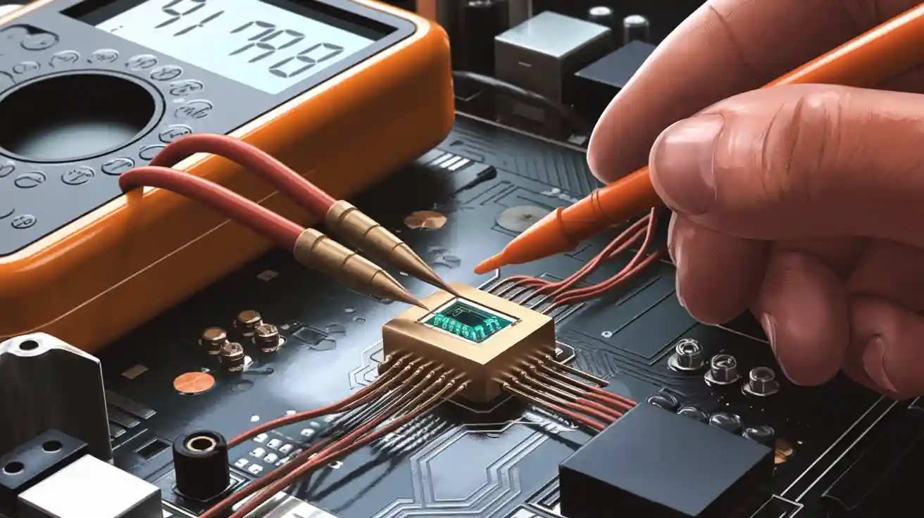
If you want to test a diode in a circuit, grab your multimeter and set it to the right mode. Touch the leads to the diode terminals. Check the reading on your meter. You don’t need to remove the diode from the board. Using the correct settings helps you get an accurate result. This process feels simple, even if you’re just starting out.
Tools and Setup
What You Need
You don’t need a lot of fancy gear to test a diode in a circuit. Here’s what you should grab before you start:
A digital multimeter (this is the main tool you’ll use)
Test leads for your digital multimeter
Optional: An oscilloscope or a function generator (these help with advanced testing, but you can skip them for basic checks)
If you have these tools ready, you’re set for a smooth testing process.
Safety Tips
Safety comes first. Before you touch anything, make sure the power to the circuit is off. You don’t want any voltage running through the diode while you test it. If you see any big capacitors nearby, discharge them. This step keeps you safe and protects your digital multimeter from damage.
Tip: Always double-check that the circuit is powered down before you start. It’s easy to forget, but it makes a big difference.
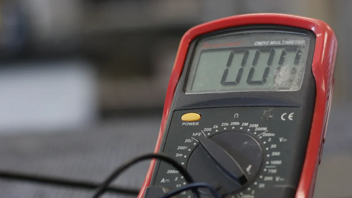
Multimeter Settings
Setting up your digital multimeter is easy. You just need to turn the dial to the right mode. If you want to use the diode test mode, follow these steps:
Make sure the circuit is off and the diode has no voltage across it.
Turn the dial on your digital multimeter to the Diode Test mode. Look for a symbol that looks like a triangle with a line.
Connect the test leads to the diode. Touch one lead to each end.
Record the reading. Then, switch the leads and record the second reading.
If your digital multimeter doesn’t have a diode test mode, you can use the resistance mode. Just turn the dial to the resistance setting (often marked with an Ω symbol). This method works for a quick check, but the diode test mode gives you more accurate results.
How to Test a Diode
Diode Test Mode
You want to test a diode right in the circuit? The easiest way is to use the diode test mode on your digital multimeter. This mode gives you a direct reading of the voltage drop across the diode. Here’s how you do it:
Turn off the power to the circuit. Make sure everything is safe.
Set your digital multimeter to diode test mode. Look for the triangle symbol with a line.
Place the red lead on the anode and the black lead on the cathode of the diode.
Check the reading. You should see a number between 0.6 and 0.8 volts for a silicon diode. Most of the time, it’s close to 0.7 volts.
Reverse the leads. Put the black lead on the anode and the red lead on the cathode. The display should show “OL” or a very high value. That means the diode blocks current in this direction.
Tip: If you see a voltage drop in both directions, the diode might be faulty. If you get zero volts, the diode could be shorted.
Resistance Mode
Sometimes, your digital multimeter doesn’t have a diode test mode. You can still test a diode using the resistance mode. This method isn’t as accurate, but it helps you spot obvious problems.
Set your digital multimeter to the resistance setting (Ω symbol).
Touch the leads to the diode terminals. Try both directions.
In one direction, you should see a low resistance. In the other, you should see a high resistance or “OL.”
Here’s a quick table to help you understand what you might see:
Multimeter Reading | What It Means |
|---|---|
0.6 – 0.8 V | Good silicon diode |
0 V | Shorted diode |
OL or high value | Open diode |
Note: Resistance mode can sometimes give strange results if other parts of the circuit connect to the diode. If you’re not sure, try using diode test mode or remove the diode for testing.
Interpreting Results
When you test a diode, you want clear answers. A good silicon diode shows a voltage drop between 0.6 and 0.8 volts in diode test mode. If you see 0 volts, the diode is shorted. If you see “OL” or no reading, the diode is open.
You might run into confusing results. Sometimes, other components in the circuit affect your readings. For example, a technician once found a failed diode in a rider mower. One coil kept firing because the diode didn’t block current. The problem was tricky to spot at first. Diodes can cause strange issues, especially in automotive circuits. If your readings don’t make sense, try testing a diode out of the circuit.
Callout: Always remember, when you test diodes in-circuit, other parts can change your results. If you’re stuck, remove the diode and test it again.
Testing a diode doesn’t have to be hard. Use diode test mode for the best results. Resistance mode works for a quick check. If you get odd readings, think about what else might be connected to the diode.
Testing a Diode with Other Methods
Oscilloscope Method
Sometimes, you want to see more than numbers. An oscilloscope lets you watch how a diode acts in real time. To do this, send a square wave through the diode. Connect the oscilloscope across the diode. You can find problems by looking at the wave’s shape.
Here’s what to look for on the screen:
Check how fast the wave goes up and down.
See if the wave’s height changes each cycle.
Notice if the line moves up or down. That is called DC offset.
Watch for strange spikes or glitches when the wave switches.
Using an oscilloscope has good and bad points compared to a digital multimeter. Look at this table:
Feature | Oscilloscope | Digital Multimeter |
|---|---|---|
Measurement Type | Shows waveforms and some voltages | Gives you direct voltage numbers |
Input Impedance | High, so it won’t mess with your circuit | Also high, safe for most circuits |
Accuracy | Not as precise as a multimeter | Very accurate |
AC Ripple Monitoring | Yes, you can see AC ripple | No, can’t see ripple |
Portability | Usually bigger and less portable | Small and easy to carry |
Ruggedness | Tough and durable | Not as tough |
Bias Voltage for Testing | Not great for testing diodes or transistors | Some models may not give enough voltage |
Tip: If you want to see how a diode handles fast signals or noise, use an oscilloscope.
Function Generator
A function generator sends different signals through a diode. You can pick the shape, speed, and strength of the signal. This tool helps you see how the diode works in real life.
Here’s how a function generator helps you test a diode:
It makes signals like square waves or sine waves. You can see how the diode reacts.
You can change the frequency and amplitude to test the diode at different levels.
It helps you check if the diode blocks current one way and lets it flow the other way.
When you use a function generator, start with low voltage and current. For a basic test, use a small current and measure the voltage across the diode. If you want a deeper check, increase the current (up to 1 amp for a 1 amp diode) and see if the voltage drop stays normal. You can also use a reverse voltage close to the diode’s rating to see if it leaks current.
Note: A function generator gives you more control and helps you find problems that a simple meter might miss.
Troubleshooting
Faulty Diode Actions
If you find a faulty diode, you need to fix it right away. Here’s a simple way to replace a bad diode in your circuit:
Test the diode with your digital multimeter to confirm it’s not working.
Find the faulty diode on the board. You can use a schematic or just look closely.
Carefully desolder and remove the diode from the circuit.
Pick a new diode that matches the old one’s specs.
Solder the new diode in place. Make sure you get the polarity right.
Test the new diode with your digital multimeter to make sure everything works.
Tip: Always check the polarity before soldering. Diodes only work one way!
Common Issues
Diodes can fail for lots of reasons. You might see problems like thermal overload, electrical overstress, or reverse bias breakdown. Sometimes, physical damage or aging causes trouble. Here are some signs and causes you should watch for:
Current going above the rated value
Open circuit failure
Short circuit failure
Burn marks or cracks on the diode
Discoloration or blackened terminals
Rapid heating when the circuit is on
Weird noises or ripples in your power supply
If you spot any of these, grab your digital multimeter and start testing. A quick visual inspection helps too. Look for burnt parts or a strange smell near the diode.
When to Remove the Diode
Sometimes, testing a diode in the circuit doesn’t give you clear results. Other parts might mess with your readings. Here’s when you should think about removing the diode:
You get confusing readings from your digital multimeter.
The circuit has lots of connected components.
You see signs of damage but can’t confirm with in-circuit tests.
Before you remove the diode, turn off all power. Discharge any big capacitors nearby. If you want, you can disconnect just one end of the diode instead of taking it out completely. This makes testing easier and safer.
Note: If you still can’t figure out the problem, try using a magnifying glass to check for tiny cracks or bad solder joints. Keeping a log of your tests and fixes helps you spot patterns if the same issue pops up again.
You now know how to test a diode in a circuit. Always use the right multimeter mode and double-check your results. Here are some common mistakes beginners make:
Misinterpreting symbols
Mixing up polarity
Using the wrong type or orientation
Stay safe by following these steps:
Turn off all power and discharge capacitors.
Post warning signs in high-voltage areas.
Inspect your test area often.
If you find a faulty diode, replace it or ask for help from a trusted source.
FAQ
Can you test a diode without removing it from the circuit?
Yes, you can test most diodes right on the board. Just use your multimeter in diode test mode. If you get strange readings, try removing one leg of the diode for a clearer result.
What does “OL” mean on my multimeter when testing a diode?
“OL” stands for “Open Loop.” Your multimeter shows this when the diode blocks current. That means the diode is working in reverse direction. You want to see “OL” in one direction for a good diode.
Why do I get different readings in-circuit compared to out-of-circuit?
Other parts in the circuit can affect your test. You might see odd numbers because of parallel paths or connected components. If you feel unsure, test the diode after removing it from the board.
What happens if I install a diode backwards?
If you put a diode in backwards, it won’t let current flow the way you want. Your circuit might not work, or you could damage other parts. Always check the polarity before soldering.
Can I use an analog multimeter to test a diode?
You can use an analog multimeter, but it’s less accurate than a digital one. You’ll see the needle move for a good diode. If the needle doesn’t move, the diode might be open or shorted.