Electrical schematics show you how electronic circuits work. When you see many lines and shapes, you can find problems faster if you know the basic schematic symbols. You learn to follow how electricity moves, fix broken parts, and even make your own devices. Try reading real schematics and practice drawing easy circuits. You will feel more sure as you start building and changing projects.
Electrical Schematics Basics
What Are Electrical Schematics
You see electrical schematics almost everywhere in electronics. These diagrams show you how parts connect and work together. Each line and symbol tells you something about the flow of electricity. You might notice shapes like zigzags, circles, or arrows. These symbols stand for things like resistors, batteries, and switches.
Electrical schematics help you understand a circuit before you build it. You can spot problems just by looking at the diagram. If you want to fix a broken device, you start with the schematic. You do not need to guess where wires go. The drawing gives you a clear map.
Tip: When you look at electrical schematics, try to match each symbol with a real part. This practice makes it easier to build or repair circuits.
Here is a simple table to show what you might see:
Symbol | What It Means |
|---|---|
Zigzag line | Resistor |
Short line | Wire |
Circle | Connection point |
Arrow | Diode |
Why Learn to Read a Schematic
You gain a big advantage when you learn to read a schematic. You can build your own projects and fix things that break. You do not have to rely on guesswork. You know exactly where each part goes.
If you want to become good at electronics, you need to understand electrical schematics. You will find these diagrams in instruction manuals, textbooks, and online guides. Beginners and hobbyists use them to learn new skills. You can follow a schematic to make sure your circuit works the way you want.
You also save time and money. You spot mistakes before you start soldering or connecting wires. You avoid damaging parts. You feel more confident as you work on new projects.
Note: Start with simple electrical schematics. Practice reading them every day. You will get better and faster at understanding circuits.
Component Symbols

When you look at electrical schematics, you see many shapes and lines. Each one stands for a different part in a circuit. You need to know these circuit symbols to read diagrams quickly. Let’s break down the most common circuit components you’ll find.
Power Sources
Power sources give energy to your circuit. You often see batteries or power supplies in schematics. The battery symbol looks like a pair of lines—one long, one short. The long line means the positive side. The short line means the negative side.
Symbol | Name | What It Does |
|---|---|---|
─ | ─ | |
⎓ | DC Supply | Gives direct current |
~ | AC Supply | Gives alternating current |
You find these symbols at the start of most diagrams. They show where electricity enters the circuit.
Tip: Always check the power source symbol before you start building. It tells you what kind of energy your circuit needs.
Ground
Ground is a key part of every schematic. It gives electricity a path to return. The ground symbol looks like a set of lines stacked on top of each other, getting shorter as they go down.
Symbol | Name | What It Means |
|---|---|---|
⏚ | Ground | Common return point |
You connect many circuit components to ground. This keeps your circuit safe and stable.
Switches
Switches let you control the flow of electricity. You turn things on or off with them. The most basic switch symbol looks like a break in a line with a lever.
Symbol | Name | What It Does |
|---|---|---|
─o/ | SPST Switch | Turns circuit on/off |
─o/o─ | DPDT Switch | Changes connections |
You see switches in car wiring diagrams a lot. They help you control lights, fans, and other devices.
Resistors
Resistors slow down the flow of electricity. The symbol is a zigzag line or sometimes a rectangle.
Symbol | Name | What It Does |
|---|---|---|
─//─ | Resistor | Limits current |
You use resistors to protect other circuit components from too much current.
Capacitors
Capacitors store and release energy. Their symbol looks like two lines facing each other, sometimes with one curved.
Symbol | Name | What It Does |
|---|---|---|
─ | ─ | |
─ | )─ | Polarized Cap |
You find capacitors in audio circuits and car wiring diagrams to smooth out voltage.
Inductors
Inductors store energy in a magnetic field. The symbol looks like a series of loops or coils.
Symbol | Name | What It Does |
|---|---|---|
─(~~~~)─ | Inductor | Stores energy in a coil |
You see inductors in filters and power supplies.
Transformers
Transformers change voltage levels. The symbol has two coils side by side, sometimes with lines between them.
Symbol | Name | What It Does |
|---|---|---|
─(~~~~)─ | ─(~~~~)─ |
You use transformers in power circuits and car wiring diagrams for charging systems.
Relays
Relays act like switches controlled by electricity. The symbol shows a box with a coil and switch inside.
Symbol | Name | What It Does |
|---|---|---|
─[ ]─ | Relay | Switches circuit on/off with a signal |
Relays help you control big currents with small signals. You find them in car wiring diagrams for headlights and horns.
Diodes
Diodes let electricity flow in one direction. The symbol is a triangle pointing to a line.
Symbol | Name | What It Does |
|---|---|---|
► | Diode |
You use diodes to protect circuit components and direct current flow.
Transistors
Transistors act as switches or amplifiers. The symbol looks like a circle with three lines coming out.
Symbol | Name | What It Does |
|---|---|---|
─(E)─(B)─(C)─ | NPN Transistor | Switches or amplifies signals |
─(E)─(B)─(C)─ | PNP Transistor | Switches or amplifies signals |
You find transistors in almost every electronic device.
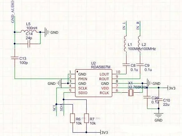
Integrated Circuits
Integrated circuits, or ICs, pack many parts into one chip. The symbol is a rectangle with pins on the sides.
Symbol | Name | What It Does |
|---|---|---|
[IC] | IC | Handles complex tasks |
You see ICs in computers, phones, and car wiring diagrams.
Logic Gates
Logic gates process signals in digital circuits. Each gate has its own symbol.
Symbol | Name | What It Does |
|---|---|---|
≥1 | OR Gate | Outputs if any input is on |
=1 | AND Gate | Outputs if all inputs are on |
⊕ | XOR Gate | Outputs if inputs are different |
You use logic gates in computers and control systems.
Optoelectronics
Optoelectronic parts use light. The symbols often show arrows for light.
Symbol | Name | What It Does |
|---|---|---|
► | < | LED |
─[ ]─< | Photodiode | Senses light |
You find optoelectronics in displays and sensors.
Other Components
You might see other circuit symbols for things like fuses, buzzers, or motors.
Symbol | Name | What It Does |
|---|---|---|
─[F]─ | Fuse | Protects circuit |
─(M)─ | Motor | Turns electricity into motion |
─(B)─ | Buzzer | Makes sound |
Note: If you ever get stuck, look for a legend or key on the schematic. It helps you match circuit symbols to real parts.
You now know the most common circuit components and their symbols. When you read car wiring diagrams or any schematic, you can spot these shapes and understand what each part does. Practice drawing these symbols and matching them to real parts. You’ll get better at reading diagrams and building circuits.
Wiring and Connections
Wire Representation
When you look at a schematic, you see lines everywhere. These lines show wiring. Wiring connects all the parts in your circuit. You follow wiring to see how electricity moves from one part to another. Sometimes, wiring looks straight. Sometimes, wiring bends around symbols. You might see wiring cross over other wiring. If wiring crosses without a dot, it means the wires do not connect. If you see a dot where wiring meets, that means the wiring connects at that point.
Tip: Always trace wiring with your finger. You can follow the path and see where electricity goes.
Connected vs. Unconnected Wires
You need to know if wiring connects or not. Connected wiring has a dot at the crossing. Unconnected wiring just crosses with no dot. This helps you avoid mistakes when you build your circuit. If you mix up connected and unconnected wiring, your circuit might not work. You can use a table to remember the difference:
Wiring Type | Symbol | What It Means |
|---|---|---|
Connected wiring | ─●─ | Wires join together |
Unconnected wiring | ── | Wires cross, no join |
Polarity
Polarity tells you which way electricity flows. Some parts need wiring to connect the right way. For example, a battery has a positive and negative side. You connect wiring from the positive side to the right part. If you mix up polarity, your circuit might not work. Look for plus (+) and minus (–) signs on the schematic. Wiring from the plus side goes to the part that needs power first.
Terminals and Nodes
Terminals are places where wiring connects to a part. Nodes are points where wiring joins together. You see nodes as dots on the schematic. You connect wiring to terminals to make your circuit work. If you miss a node, your wiring might not carry electricity where you want.
Let’s look at a simple example. You have a battery, an LED, and a resistor. Wiring goes from the battery’s positive terminal to the resistor. More wiring connects the resistor to the LED. Then, wiring goes from the LED to the battery’s negative terminal. Electricity flows through the wiring, lights up the LED, and returns to the battery.
+ (Battery) ── wiring ── [Resistor] ── wiring ── [LED] ── wiring ── - (Battery)
You can see how wiring connects each part. You follow the wiring to understand how the circuit works.
Automotive Wiring Diagrams
Car Wiring Diagrams
You find automotive wiring diagrams in car manuals and repair books. These diagrams show how each wire and part connects inside your car. You can see the path for things like headlights, radios, or the starter motor. Every symbol stands for a real part, such as a fuse, relay, or switch. Automotive wiring diagrams use some of the same symbols as regular electrical schematics. But they also have special symbols for car parts.
Here are some things you will see in car wiring diagrams:
Different colored lines for each wire
Labels that tell you wire colors, like BLK for black or RED for red
Special symbols for car parts, like horns, sensors, or ignition coils
Tip: Always look at the legend or key on the diagram. It helps you match symbols and wire colors to real parts in your car.
Reading Automotive Schematics
When you read car wiring diagrams, look for the power source, ground, and the path electricity takes. Follow the lines from the battery to each device. If you see a break or a switch, you know where you can turn something on or off. Automotive wiring diagrams often show connectors and pin numbers. This helps you find the exact spot to test or fix.
You will see some differences from regular schematics. Automotive diagrams can look more crowded. They often use more labels and numbers. But the main idea is still the same. Look for symbols, follow the lines, and see how everything connects.
Knowing how to read wiring diagrams helps you fix problems faster. If your car’s lights do not work, you can follow the wiring and find what is broken. You can also use these diagrams to add new things, like a backup camera or extra lights.
Note: Start by reading simple wiring diagrams. Then try harder automotive wiring diagrams as you get better.
Practical Tips
Build and Troubleshoot
You can start building circuits once you know the basic wiring diagram symbols. Try simple projects like lighting up an LED or making a buzzer sound. When something does not work, look at your schematic. Check each symbol and follow the wires. This helps you find mistakes fast. You might see a wire in the wrong place or a part turned the wrong way. If you get stuck, compare your work to the schematic again. You will get better at diagnosing electrical issues with practice.
Tip: Keep a notebook. Write down what works and what does not. This helps you learn from each project.
Modify Circuits
You do not have to stick to the original plan. Once you feel comfortable, try changing your circuits. Swap out a resistor for a different value. Add a switch or another LED. Use the wiring diagram symbols to plan your changes before you build. This way, you can see how each part fits into the circuit. You will learn how small changes affect the whole project.
Draw your new schematic before you start.
Double-check the symbols and connections.
Test your circuit step by step.
Advance Your Skills
You can take your skills further by learning about more complex circuits. Try reading bigger schematics with more parts. Look for patterns in the wiring diagram symbols. You will start to see how different circuits use the same ideas. If you want to design your own projects, learn about circuit design software and PCB layout. These tools help you make neat, safe, and reliable circuits.
Note: The more you practice, the easier it gets. You will soon feel confident reading any schematic and fixing problems on your own.
You now know why schematic symbols are important in electronics. Reading diagrams helps you find problems and build circuits easily. You can practice by drawing your own schematics or fixing something simple. If you want to learn more, you can look into harder circuit design and analysis.
Keep in mind, every project you do makes you better. You will be able to read schematics well and start making your own electronic projects.
FAQ
What are electrical diagrams and why do you need them?
Electrical diagrams show how parts connect in a circuit. You use diagrams to build, fix, or change electronics. Diagrams help you see where wires go. They also show what each symbol means. Using diagrams saves time and helps you avoid mistakes.
How do you read symbols in diagrams?
First, look at each symbol in the diagram. Try to match symbols to real parts like resistors or switches. Diagrams use shapes and lines to show how electricity moves. If you practice reading diagrams every day, you will get better.
Can you use diagrams for car repairs?
Yes, you can! Car manuals have diagrams for wiring and parts. These diagrams help you find problems with things like lights or radios. You follow the diagram to see how wires connect. Using diagrams makes car repairs easier and faster.
Why do some diagrams look different?
Some diagrams use special symbols for certain devices. Car diagrams might show wire colors or connector numbers. Home diagrams use different symbols for outlets or switches. Always check the legend in the diagram to know what each symbol means.
How do you make your own diagrams?
You draw diagrams by using simple shapes for each part. Start with a battery, then add wires, switches, and other parts. Diagrams help you plan before you build. You can use free software or just paper to make diagrams.
Tip: Try drawing diagrams for small circuits. You will learn faster and make fewer mistakes.
Step | What You Do |
|---|---|
1 | Pick parts for your diagram |
2 | Draw symbols in your diagram |
3 | Connect wires in your diagram |
4 | Check your diagram for mistakes |
Example:
(Battery) ── [Switch] ── [LED]
Draw diagrams like this to show connections.