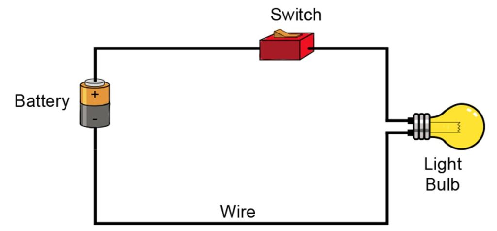
Circuit symbols are frequently used in electrical and electronic circuit Schematics, that displays how a circuit is connected. Circuit symbols are basic components for constructing and designing any electrical or electronic circuit. The pictorial representation of different electrical components in an electrical circuit or diagram is called an electrical symbol. A circuit diagram consists of many circuit symbols like resistors, capacitors, inductors, transistors, diodes, batteries, switches etc. Each circuit symbol has its own characteristic and value.
This article will help you to read, learn, and understand the most frequently used circuit symbols for analyzing and designing circuit schematics.

2. Common Electrical Symbols in Schematics
i. Electrical Power Source Circuit Symbols
Battery:
A battery is an electric component that provides a constant electric potential difference (a fixed voltage) across its terminals. A battery comprises electrochemical cell(s) that can easily convert chemical energy into electrical energy. It is a core part of a circuit. There are three main parts of batteries, and these are the electrolyte, cathode, and anode.
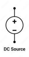
DC Voltage Source
In any electrical power system, there are two categories of electrical sources, i.e., DC and AC voltage sources. DC Voltage means Direct Current Voltage. It refers to a voltage source with constant polarity that provides DC current (DC). Usually, DC voltage source or power is supplied by batteries. But sometimes you can use fuel cells and solar cells for the same purpose.
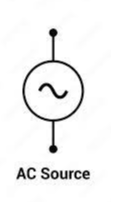
AC Voltage Source
AC voltage source refers to an alternating current voltage source. AC voltage magnitude fluctuates, and the power does not always maintain a constant. The voltage or power fluctuations are caused by electrical devices connected to an AC voltage source. The circuit symbol for an AC voltage source in a circuit schematic is as follows.
Ground:
Grounding in electrical circuits protects your electronic devices and circuits from any short circuits, faults, or electrical overloads. Grounding in electrical schematics provides a low-resistive path for the high fault currents to flow toward the earth that safeguards your power system or equipment. Without grounding, the electrical circuit or system will be damaged. The common electrical symbol for ground is given as follows.

s
ii. Passive Electrical Symbols
Resistor:
A resistor is a passive element in an electrical circuit that regulates the flow of electrical current in any electrical or electronic circuit. A resistor consumes the power. That’s why it is called a passive electrical component. The most common circuit symbol for a resistor is a zigzag line like as follows.

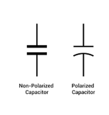
Capacitors:
Capacitors are passive electrical components that consist of two or more plates of conducting material separated by a dielectric material (an insulator). The purpose of a capacitor in electrical schematics is to store energy in the form of electrical charges that produce a potential difference across its plates. Capacitors are also widely used in printed circuit board manufacturing and assembly. Capacitance of a capacitor is denoted by L. The most common circuit symbol used for capacitor is.
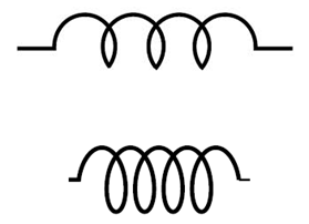
Inductors:
An inductor is a two-terminal passive electrical component that resists the sudden change in current. They are also known as chokes or coils. An inductor stores energy in the form of an electromagnetic field. Surface mount inductors (SM) are mounted on the top of the printed circuit board on pads, while through hole (TH) inductors are placed on the PCB top with leads fed through via holes in the printed circuit board. The basic circuit symbol for an inductor is shown as follows.
iii. Switches, Relays & Transformer
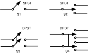
Switches:
In an electrical schematic, a switch is a component that opens or closes a circuit. Opening the circuit means turning off the circuit from the power system, while closing the circuit means making the flow of current and connecting the circuit to the power supply. There are many types of switches, such as Single Pole Single Throw (SPST), Single Pole Double Throw, Double Pole Single Throw (DPST), and Double Pole Double Throw (DPDT).
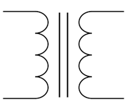
Relays and Transformers Circuit Symbol:
In electrical power system, transformer is a passive device that transfers electrical energy through electromagnetic induction. The basic function of a transformer is to step up or step down the voltage. A transformer may be single-phase or three-phase. It is represented in an electrical circuit or power system as:
Relays in electrical circuits are actually switches that open or close circuits electronically or electromechanically. A relay operates automatically when it receives signals from external sources. Relays are commonly used in industrial automation systems, home appliances, HVAC systems, etc. A common circuit symbol used for a relay in a circuit schematic is:

3. Common Electronic Circuit Symbols
i. Diodes and Transistors (Active Electronic Symbols)
Diode, Zener Diode, LED:
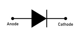
A diode is a two-terminal semiconductor electronic device that acts as a one-way switch for current. It is typically made up of silicon and allows current in one direction. When a diode is used as a rectifier, then it converts AC voltage to DC. The common circuit symbol used for a diode is as follows:
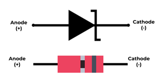
A Zener diode is a specific type of diode that allows current in reverse direction when a particular voltage (threshold voltage) is exceeded. The process of reverse conduction of current of a Zener diode is called the Zener effect. The representation of the circuit symbol for the Zener diode is:
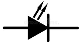
A light-emitting diode (LED) is also a semiconductor device that emits light when current passes through it. This process of LED is called electroluminescence. They are used in wide applications.
Bipolar Junction Transistor (BJT):
A bipolar junction transistor (BJT) is a semiconductor, solid-state, current-controlled device. It consists of two PN junctions that connect the three terminals called Emitter, Base, and Collector terminals. The arrangement of these three layers distinguishes the two main types of BJTs, i.e., NPN and PNP.
The NPN transistor is made up of two n-type semiconductors separated by a thin layer of p-type.
While PNP transistors consist of two p-type semiconductors separated by thin layer of n-type.

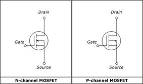
MOSFET:
Metal Oxide Semi-Conductor Field Effect Transistor (MOSFET) is a field effect transistor with a MOS structure. It is a three-terminal device with Gate (G), Source (S), and Drain (D) terminals. MOSFET is basically used as a switch, voltage-controlled current device, or as an amplifier. There are two major types of MOSFET, i.e., N-Channel and P-Channel.
ii. Integrated Circuits and Microcontrollers
Operational Amplifier (Op-Amp):
An operational amplifier is an integrated circuit that can amplify weak signals or voltage differences between two inputs. Op Amp amplifies both DC and AC signals.

Logic Gates:
A logic gate is used to perform logical operations by giving input to it and providing output as 0 or 1 depending on the gate type and input given. The operation of logic gates is based on mathematics or Boolean algebra. Some of the major logic gate circuit symbols are as follows.

Microcontrollers:
A microcontroller is a single unit integrated circuit (IC) having features of a central processing unit that ranges from 4-bit to 32 or 64-bit processors. Microcontrollers are used in industrial control systems, electronics, IoT devices, etc.

4. How to Read and Understand Circuit Symbols & Circuit Schematics
Understanding the circuit symbols is important to represent the electrical and electronic schematics. These symbols help the electrical engineers, PCB designers, electronic device manufacturers, and technicians to analyze and design circuits easily. You can understand circuit symbols and diagrams as follows:
- Identify the power source that may be either AC or DC.
- Identify the flow of current, i.e., the positive and negative terminals of the circuit.
- Look for basic circuit components, i.e., resistors, capacitors, and inductors.
- Understand the circuit connection, which may be either series or parallel.
- Look for component values, e.g., 10kΩ resistor, 100µF capacitor, 50µH, etc.
- Identify the control signals, feedback paths or data flow in circuit diagram.
6. How to Use Circuit Symbols in Real Projects
You can use circuit symbols in your real project by explaining the circuit schematic and identifying circuit components. Then assemble the circuit components based on their values and specifications. Build, analyze, and test your electrical or electronic circuit on a breadboard using circuit wire connections.
When verified, use PCB design software to convert your circuit into a printed circuit board layout, ensuring the right routing and component placement. For your professional PCB project, Wonderful PCB can assist you to convert your schematics into a high quality printed circuit board.
Conclusion
Circuit symbols are important for understanding, designing, and troubleshooting circuit schematics. Circuit symbols in circuit schematics help electrical engineers, PCB designers, and electronic manufacturers to analyze circuit behavior and design the electrical power system or electronic device. By understanding the circuit symbols, you can effectively work and manage your electrical and electronic systems. Wonderful PCB will suggest the accurate circuit symbols for your electronic project and printed circuit board design.