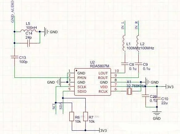
This circuit Schematic Diagram is an FM radio receiver module built around the RDA5807M as the core IC. It mainly implements FM signal reception, audio output, and basic control functions. The analysis below is divided into core components, functional modules, and key design parameters.
1. Core Component and Pin Functions
Core IC: RDA5807M
The RDA5807M is a highly integrated FM radio receiver IC that supports FM broadcast reception and I2C / SDIO serial control. Based on the schematic, the key pins and their connections are summarized below:
| Pin Name | Function | Connected Component / Net | Description |
|---|---|---|---|
| ROUT | Right-channel audio output | Direct output (no extra components shown) | Provides right-channel analog audio |
| LOUT | Left-channel audio output | Direct output (no extra components shown) | Provides left-channel analog audio |
| RCLK | Clock signal pin | No explicit external connection (likely internal sync) | Internal clock synchronization |
| VDD | Power supply input | 3V3 power net | 3.3V DC power supply |
| GND | Ground | Global GND net | Common power and signal ground |
| SDIO | Serial data I/O | Pin 3 (control signal) | Communication with MCU for tuning, volume control, etc. |
| SCLK | Serial clock | Pin 2 (clock signal) | Clock signal for SDIO communication |
| FMIN | FM signal input | Pin 5 | Receives FM RF signal from antenna |
| X1 | Crystal oscillator input | 32.768 kHz crystal | Provides reference clock for stable frequency operation |
2. Functional Module Breakdown
2.1 Power Supply Module
- Input Voltage: 3.3V DC (regulated)
- Filtering Components:
- C8 (0.1µF), C9 (0.1µF): High-frequency decoupling capacitors between VDD and GND, suppressing power noise
- C10 (22µF): Bulk electrolytic capacitor for low-frequency filtering and energy storage
- C26 (0.1µF): Additional decoupling to further improve power stability
This multi-stage filtering ensures stable and low-noise power delivery to the FM receiver IC.
2.2 FM Signal Reception Module
- Signal Input:
- The FMIN pin (Pin 5) connects to an external FM antenna (antenna element not shown in the schematic)
- Receives FM broadcast signals in the 87–108 MHz band
- Crystal Oscillator Circuit:
- A 32.768 kHz crystal (X1) provides an accurate reference clock
- Ensures precise FM tuning and prevents frequency drift during station selection
2.3 Control and Communication Module
- Communication Interface:
- SDIO (Serial Data) + SCLK (Serial Clock)
- Compatible with I2C or similar serial communication protocols
- Used to interface with an external MCU (e.g., microcontroller)
- Pull-up Resistors:
- R6 (10kΩ) for SDIO
- R7 (10kΩ) for SCLK
- Both are connected to 3V3, ensuring stable logic levels and reliable communication
2.4 Audio Output Module
- Audio Outputs:
- ROUT: Right-channel analog audio
- LOUT: Left-channel analog audio
- These outputs can be:
- Connected directly to headphones
- Connected to speakers (note: an external audio amplifier is required for higher power output)
2.5 Auxiliary Filtering and Matching Module
- Inductors:
- L1, L2 (100 nH): Likely used for RF impedance matching or input filtering at the FM front end
- Helps reduce signal reflection and improve reception sensitivity
- Capacitors:
- C13 (100 pF), C14 (24 pF): Work with inductors to form an LC filter network
- Suppress high-frequency interference and purify the FM signal
- Grounding:
- Multiple GND connections indicate a global common-ground design
- Reduces noise and improves overall circuit stability
3. Key Parameters and Design Features
- Operating Voltage: 3.3V
- Fully compatible with mainstream MCUs without level shifting
- Crystal Frequency: 32.768 kHz
- Industry-standard reference frequency for stable timing
- Control Method: SDIO + SCLK serial interface
- Simplified routing, only two control lines required
- Filtering Design:
- Multiple power decoupling capacitors (0.1µF + 22µF)
- LC filtering on the RF front end for strong noise immunity
- Audio Output:
- Dual-channel analog audio (ROUT / LOUT)
- Supports stereo FM playback
4. Application Scenarios and Expansion Suggestions
Typical Applications
- Portable FM radios
- Smart speakers with FM radio functionality
- MCU-controlled FM receiver systems
Expansion Options
- Use an external telescopic antenna or PCB antenna to improve reception sensitivity
- Add an audio power amplifier (e.g., LM386) to ROUT/LOUT for driving larger speakers
- Enable advanced features via MCU control:
- Automatic station scanning
- Preset channel storage
- Digital volume control
5. Design Notes and Precautions
- Power Stability:
- Ensure low ripple on the 3.3V supply to avoid audio noise or unstable reception
- Grounding:
- Use a solid and consistent ground reference
- Avoid potential differences between power ground and audio ground to prevent noise
- Impedance Matching:
- The antenna connected to FMIN should be impedance-matched (typically 50Ω) for optimal reception
- Component Selection:
- Use a high-accuracy 32.768 kHz crystal
- Prefer NP0 / C0G capacitors for RF and timing-related components due to superior stability
Radio circuit program code
RDA5807.H
/*
**==============================================================================
** RDA5807.H:
**
**  Description:
**
**==============================================================================
*/
#ifndef __RDA5807__
#define __RDA5807__
//------------------------------------------------------------------------------

#ifdef RDA5807_GLOBALS
   #define RDA5807_EXT
#else
   #define RDA5807_EXT extern
#endif // RDA5807_GLOBALS
//------------------------------------------------------------------------------
//==============================================================================

void RDA5807Init(void);

//------------------------------------------------------------------------------

RDA5807_EXT uint16_t g_nRDA5807Channel;

//------------------------------------------------------------------------------
void RDA5807Setup(void);
void RDA5807I2CWrite(uint8_t * pucData, int nLength);
void RDA5807SetChannel(float freq);


//==============================================================================
//             END OF THE FILE : RDA5807.H
//------------------------------------------------------------------------------
#endif // __RDA5807__

/*
**==============================================================================
** RDA5807.C:
**
**==============================================================================
*/

//------------------------------------------------------------------------------
#include "stm32f0xx_hal.h"
#include "stm32f0xxa.h"

#define RDA5807_GLOBALS        1              // Define the global variables
#include "RDA5807.H"

//------------------------------------------------------------------------------
#define RDA5807_BOOT_LENGTH     12
uint8_t RDA5807_boot_config[] = {
    0xc1, 0x03,                             // Register 0x2
    0x00, 0x00,                             // Register 0x3
    0x0a, 0x00,                             // Register 0x4
    0x88, 0x0f,                             // Register 0x5
    0x00, 0x00,                             // Register 0x6
    0x42, 0x02,                             // Register 0x7
};


//------------------------------------------------------------------------------
#define RDA5807_TUNE_CONFIG_LENGTH  4

uint8_t RDA5807_tune_config[] = {
    0xc0, 0x01,                             // Register 2
    0x00, 0x00,                             // Reigster 3
};

void RDA5807SetTuneConfig(uint16_t channel) {
    RDA5807_tune_config[2] = (uint8_t)(channel >> 2);
    RDA5807_tune_config[3] = (uint8_t)(((channel & 0x3) << 6) | 0x10);
}

//------------------------------------------------------------------------------

void RDA5807Init(void) {

/* Assumin band starts at 87.0MHz(per setting below)
 * and channel spaceing of 100kHz(0.1Mhz)(per settings below)
 * then channel can be derive as floowins:
 * channel = (<desired freq in MHz> - 87.0) / 0.1
 *
 * which is ave as:
 * <10x desired ferq in MHz> - 870
*/
    g_nRDA5807Channel = 6;
    RDA5807Setup();
}

//------------------------------------------------------------------------------
extern I2C_HandleTypeDef hi2c1;
void RDA5807I2CWrite(uint8_t * pucData, int nLength) {
    HAL_I2C_Master_Transmit(&hi2c1, 0x20, pucData, nLength, 10);
}

//------------------------------------------------------------------------------
void RDA5807Setup(void) {
    RDA5807I2CWrite(RDA5807_boot_config, RDA5807_BOOT_LENGTH);
    RDA5807SetTuneConfig(g_nRDA5807Channel);
    RDA5807I2CWrite(RDA5807_tune_config, RDA5807_TUNE_CONFIG_LENGTH);
}


void RDA5807SetChannel(float freq) {
    g_nRDA5807Channel = (int)((freq - 87.0) * 10.0 + 0.5);
    RDA5807SetTuneConfig(g_nRDA5807Channel);
    RDA5807I2CWrite(RDA5807_tune_config, RDA5807_TUNE_CONFIG_LENGTH);
}

//==============================================================================
//                END OF THE FILE : RDA5807.C
//------------------------------------------------------------------------------