You hear about RMS noise and standard deviation in electronics, as well as SNR. These terms help you understand how much noise affects your circuits. Noise is an unwanted signal. Here is a quick look at what these terms mean:
Term | Definition |
|---|---|
RMS Noise | RMS noise shows the real value of changing noise signals. |
Standard Deviation | This tells you how much the signal values change from the average. |
Signal-to-Noise Ratio | SNR compares your signal’s strength to the background noise. |
RMS noise and standard deviation in electronics can significantly impact how well your PCB functions. A high SNR indicates better connections and fewer mistakes during assembly. Conversely, a low SNR can lead to unreliable circuits and poor outcomes in manufacturing.
Key Takeaways
RMS noise tells you the true amount of noise. It helps you see how noise changes your circuits.
Standard deviation shows how much signals change from the average. This helps you know how noise affects performance.
A high signal-to-noise ratio (SNR) means signals are clear. It also means there are fewer mistakes. A low SNR can make circuits not work well.
To make SNR better, use eye diagrams and spectrum analyzers. These tools help you find and lower noise.
Good grounding, shielding, and placing parts well are important. These steps help lower noise and make circuits work better.
RMS Noise and Standard Deviation in Electronics
Historical Foundations of Noise Analysis
People started learning about noise a long time ago. Even before modern electronics, people like Pythagoras studied sound. Over time, new inventions made the world noisier.
During the Industrial Revolution, machines made lots of new sounds. It became harder to hear nature. Later, the Electric Revolution brought more ways to make and change sounds. People noticed that life was full of signals and noise.
Here are some big moments in noise history:
Milestone/Contribution | Year | Key Figure(s) |
|---|---|---|
Development of sound-level meters | 1917 | AT&T, Leo Beranek |
Invention of the transistor | 1947 | John Bardeen, Walter Brattain, William Shockley |
Construction of anechoic chambers | 1920s | E. H. Bedell (Bell Laboratories) |
As technology got better, measuring noise became more important. The world changed from quiet to noisy. This made noise measurement a big deal for electronics.
RMS Noise: Definition and Calculation
RMS noise and standard deviation show how much unwanted signal is in your circuits. RMS means “root mean square.” When you measure RMS noise, you find the real value of changing noise. This number tells you how much noise can bother your system.
You use special tools to measure RMS noise. A true RMS voltmeter gives good readings. Oscilloscopes show noise as waves and let you see the highest and lowest points. Waveform analyzers and spectrum analyzers help you measure RMS voltage in a certain range.
To find RMS noise, do these steps:
Take lots of noise measurements.
Square each measurement.
Find the average of the squared numbers.
Take the square root of that average.
This gives you one number showing the noise power in your system. You use this number to compare circuits or check if your PCB design is good enough.
Standard Deviation: Meaning and Use
Standard deviation is another way to measure noise. In electronics, it shows how much signal values move away from the average. You find it by squaring the differences from the mean, averaging them, and taking the square root. This shows how strong the changes are.
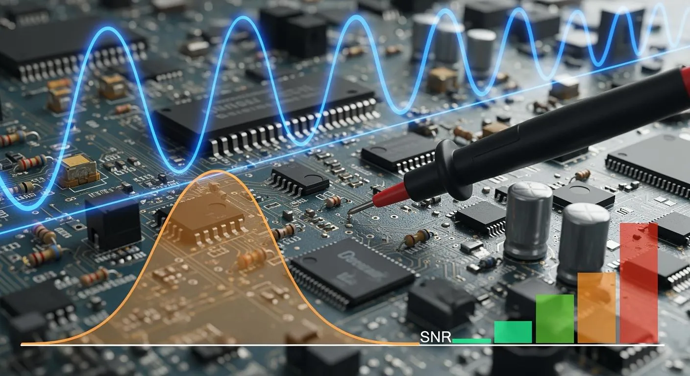
Standard deviation is used with Gaussian noise. Gaussian noise is random and makes a bell-shaped curve. It comes from things like heat in wires, shot noise, or black-body radiation. Standard deviation helps you see how much this noise affects your signal.
You use standard deviation in many ways:
It helps test communication channels by adding white noise.
It shows how much noise can change your signal in real life.
It helps you design circuits that work well even with noise.
When you design and build PCBs, you need to know about RMS noise and standard deviation. These numbers help you find problems, make better designs, and check if your products work right. By learning about noise, you can build stronger and more reliable electronics.
Comparing RMS Noise and Standard Deviation
Key Differences and Connections
RMS noise and standard deviation are both used in electronics. They help you see how noise affects a signal. RMS noise tells you the real size of changing noise in a circuit. Standard deviation shows how much values move from the average. These two ideas seem alike, but they are not the same.
Here is a table to show how they differ:
Concept | Description |
|---|---|
RMS Noise | Finds the root mean square of noise. For flat signals, it can match standard deviation. |
Standard Deviation | Shows how much values change from the mean. Used in many areas, not just electronics. |
Application | RMS noise is for electronics. Standard deviation is used in many fields. |
RMS noise is mostly for electronics. Standard deviation is used in math, science, and engineering. Sometimes, both give the same answer, like when noise is normal.
RMS noise is used in electronics.
Standard deviation is used in statistics.
Sometimes, they are equal if the noise is normal.
Gaussian Noise and Metric Equivalence
Many electronic systems have Gaussian noise. This noise makes a bell-shaped curve when you graph it. In these cases, RMS noise and standard deviation mean the same thing. Both show how much noise spreads from the average.
RMS noise is the standard deviation for noise in signals. You need this number to find the signal-to-noise ratio. You divide the difference between the highest signal and background by the RMS noise. This shows how close RMS noise and standard deviation are in electronics.
Applications in Circuit and PCB Design
You use RMS noise and standard deviation in real projects. When you make a PCB, you want less noise so your signal is clear. You can use tools like NI Multisim to test noise. You might check thermal noise from resistors or shot noise from semiconductors. You check if your amplifier has a signal-to-noise ratio of 100dB. You figure out the highest RMS voltage noise at the input.
You also look at noise at different frequencies. You use power spectral density curves to see how noise changes. You keep analog and digital circuits apart to stop noise from spreading. You use split ground planes to block digital noise. You put decoupling capacitors near power pins to filter high-frequency noise.
You need to lower noise for good power in mixed-signal designs.
You use different power for analog and digital circuits.
You use good grounding to stop noise problems.
You put decoupling capacitors near IC power pins to filter noise.
Knowing about RMS noise and standard deviation helps you make better circuits. You keep your signal strong and noise low. Your PCB designs work better and last longer.
SNR and System Performance

What Is SNR in Electronics
You need to know how much unwanted noise affects your electronic systems. The signal-to-noise ratio, or SNR, helps you measure this. SNR tells you how strong your signal is compared to the background noise. A high SNR means your signal stands out clearly. A low SNR means noise can hide or change your signal.
You can calculate SNR using a simple formula. First, measure the average signal when your system is working. Next, measure the average noise when the system is off or in the dark. Then, find the standard deviation of the signal with noise. The formula looks like this:
SNR = (S - D) / σρ
S is the average signal with light or activity.
D is the average dark or baseline value.
σ is the standard deviation of the signal with light.
ρ is the number of pixels or points you measure.
You use SNR to check if your system can send or receive clear information. If SNR is high, your system works better and makes fewer mistakes. If SNR is low, noise can cause errors or lost data.
SNR Thresholds and Reliability
You want your electronic systems to work well every time. SNR helps you set limits for reliable operation. In many places, you need an SNR of at least 15 to 20 decibels (dB) for good performance. This level keeps noise from causing too many problems.
Here is a table that shows SNR standards for different uses:
Environment/Application | Minimum SNR (dB) |
|---|---|
Enterprise | 35 |
Voice Networks | 25 |
WiFi 7 | Higher than older standards for multi-gigabit speeds |
You can also use these simple rules:
Over 40 dB SNR gives you an excellent signal (5 bars).
25 to 40 dB SNR gives you a very good signal (3 to 4 bars).
15 to 25 dB SNR gives you a low signal (2 bars).
10 to 15 dB SNR gives you a very low signal (1 bar).
5 to 10 dB SNR means almost no signal.
If your SNR drops below these levels, your system may lose data or sound bad. You need to keep SNR high to make sure your devices work every time.
SNR in WiFi, Audio, and PCB Assembly
You see SNR in action in many real-world systems. In audio electronics, you want SNR to be at least 90 dB for Hi-Fi sound. This keeps music and voices clear and free from background noise. You use low-noise parts and careful design to reach this level.
For video systems, you need a high SNR to keep images sharp. A value of 30 dB or more is important for 4K video. If SNR drops, you see fuzzy pictures or strange colors.
WiFi systems also depend on SNR. In WiFi 6 and WiFi 7, you need higher SNR for fast and stable connections. Good design can reduce SNR loss by 6 dB as you move away from the router. This helps you get better wireless coverage and fewer dropped connections.
When you design PCBs, you use SNR to find and fix problems. You want to minimize noise, reduce signal loss, and keep communication between parts strong. You can use tools like eye diagrams, time-domain reflectometry, and spectrum analyzers to check SNR. These tools help you spot noise, ringing, or weak signals.
Maintaining signal integrity involves a complex interplay of factors, including minimizing noise, reducing signal degradation, and ensuring reliable communication between components.
You can follow these steps to improve SNR in your PCB designs:
Use eye diagrams to check signal quality.
Try time-domain reflectometry to find faults.
Use spectrum analyzers to spot noise and ringing.
You need to keep SNR high to make your electronics reliable. Good SNR means your signals stay clear, your noise stays low, and your products work as they should.
Importance for Design and Troubleshooting
Reliability and Optimization
You need to know about RMS noise, standard deviation, and SNR when you work on electronic systems. These numbers help you find problems and make your designs more reliable. If SNR is high, background noise stays low. This means your signal is clear. You get data sent with no mistakes in communication systems. You also get better sound and video, which makes the whole system work better.
Studies show that learning about different noise sources and how they change device performance helps make electronics more reliable. You can use noise data to check if your devices are good. This way works well for electronics and helps you find problems early.
Tools for Noise Analysis in PCB Design
Modern software gives you strong ways to control noise when you build PCBs. You can use tools like Cadence to study and lower noise. These programs have features that let you see how noise changes your signal and system.
Feature | Benefit for Noise Management |
|---|---|
Advanced simulation capabilities | Helps in analyzing system interactions to identify noise issues. |
Signal integrity analysis | Assesses the quality of signals to prevent noise coupling. |
3D visualization | Provides a spatial understanding of components to mitigate noise. |
Mixed-signal simulation | Identifies potential noise coupling and signal integrity problems. |
You can use these tools to test your design before you build it. You find noise problems and fix them early. This saves you time and money.
Best Practices for Engineers
You can follow some best steps to keep noise low and make your system work better. Try these ideas:
Use good signal filters, like low-pass or high-pass filters.
Make sure you have good grounding and shielding to block noise.
Place parts and wires well to keep them short and cool.
Use noise reduction methods, like digital or adaptive filtering.
Pick good parts that make little noise and have low distortion.
Group parts by what they do to cut down on delays.
Put important parts first for better connections.
Keep analog and digital parts apart to stop interference.
Put decoupling capacitors close to ICs to filter noise.
Do not use long, side-by-side wires to lower interference.
Use boards with many layers to keep power and ground apart.
You can look at real examples to see how these ideas help. For example:
Case Study | Description |
|---|---|
Telecom Company X | Made shielding to stop crosstalk in fiber optic networks, making things work better. |
Manufacturing Firm Y | Used signal separation to lower interference, which made production faster. |
Aviation Industry Z | Changed signal frequencies to cut crosstalk, making communication safer and clearer. |
You can use these ways to keep noise low and your signal strong. Your designs will work better and last longer.
You help make electronics work well by learning about RMS noise, standard deviation, and SNR. These numbers let you control noise and make PCB design better. Good grounding and smart stackup design can lower noise and help meet EMC rules:
Issue | Solution |
|---|---|
Bad grounding | Use stronger ground connections |
Poor stackup | Design to stop extra noise |
You can use computer tools, better parts, and smart layouts to cut down noise. As technology gets better, real-time data and machine learning will help you find and fix noise faster.
FAQ
What is the difference between RMS noise and standard deviation?
RMS noise helps you find the true amount of changing noise in circuits. Standard deviation tells you how far values are from the average. Sometimes, both numbers are the same, especially with Gaussian noise in signal processing.
Why does SNR matter in data acquisition systems?
You want a high SNR to get clear signals in data systems. If SNR is low, you might miss important details. Good SNR lets you collect correct data and makes your system work better.
How does noise affect image quality?
Noise looks like random dots or grain in pictures. More noise makes pictures look worse. You can make images better by using good filters and designing your analog-to-digital converter carefully.
Where do you use high-performance measurement instrumentation?
You use high-performance measurement tools in labs, factories, and research places. These tools help you measure tiny signals and find noise. They make sure your results are right and trustworthy.
What role does an analog-to-digital converter play in noise control?
An analog-to-digital converter changes real signals into digital data. Good converters lower noise and keep signals clear. This step is very important for signal processing.