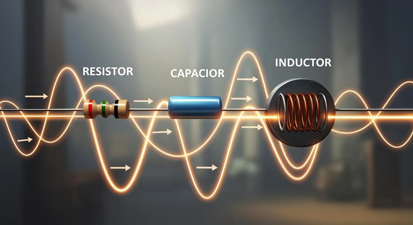
When you look at how an electrical circuit works with AC voltage, you find something cool. Resistors, capacitors, and inductors each change how the circuit acts. Impedance, reactance, and phase difference start to matter a lot. AC voltage and circuit analysis help you see how these parts work together. Advanced PCB design and simulation tools make your job easier and better.
Tip: Simulation tools can help you find problems before you build a real circuit.
Key Takeaways
AC voltage goes back and forth. This is not like DC voltage. Knowing this helps you understand how electricity works in homes and stores.
Impedance is made of resistance and reactance in AC circuits. You should always check impedance. This helps you not make mistakes when you study circuits.
Capacitors and inductors change current and voltage in different ways. Capacitors make current come before voltage. Inductors make current come after voltage.
Simulation tools like OrCAD PSpice let you test circuits first. This helps you save time. It also helps you make fewer mistakes in your designs.
You should follow good rules in AC circuit design. Use the right impedance control and check for reliability. This makes your circuits work better and last longer.
AC Voltage Basics
What Is AC Voltage
You use ac voltage all the time. You might not notice it. Ac voltage means the current changes direction. It goes back and forth. Direct current only moves one way. Ac voltage switches directions many times. This makes ac voltage different. You find ac voltage in homes and businesses.
Here is a table that shows how ac voltage and dc voltage are not the same:
Property | AC Voltage | DC Voltage |
|---|---|---|
Direction of Flow | Changes between positive and negative | Goes in one direction |
Waveform | Has a wave shape | Stays the same |
Frequency | Depends on where you live | No frequency, stays steady |
Applications | Good for sending power far away | Used for gadgets and batteries |
Energy Storage | Not used for storing energy | Used in batteries and circuits |
Phase Shift | Changed by inductors and capacitors | No phase shift |
Ac voltage goes up and down in a pattern. It switches between positive and negative. Ac voltage has frequency and amplitude. It is used to send electricity far because it works with transformers. Dc voltage stays the same and is used in batteries and USB ports.
Sine Wave and Vrms
Most ac voltage follows a sine wave. The sine wave goes up to a high point, drops to zero, goes down to a low point, and returns to zero. You can use a math equation to show ac voltage:
V(t) = Vp * sin(2πft)
Vp is the highest voltage. f is the frequency. t is time. The peak voltage is the biggest value. Vrms is used to measure ac voltage. Vrms tells you how strong ac voltage is. It helps you figure out power.
Vrms is found by taking the square root of the average of the squared values.
For a sine wave, Vrms = 0.7071 x Vpeak.
Example: If the peak voltage is 25 volts, Vrms = 0.7071 x 25V = 17.68V.
Vrms lets you compare ac voltage to dc voltage. It shows how much heat is made in a resistor.
Real-World AC Examples
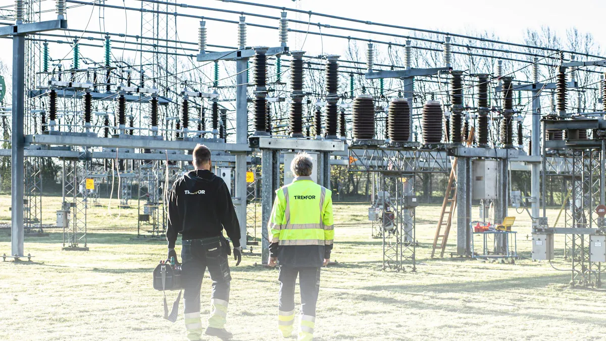
You see ac voltage every day. It powers lights, appliances, and computers. Ac voltage runs your fridge, TV, and air conditioner. Factories use ac voltage for big machines. Many places use three-phase ac voltage. It gives steady power and works for heavy loads.
Ac voltage is used for lights and appliances.
Factories use ac voltage for machines.
Three-phase ac voltage is used for steady power in industries.
Note: Ac voltage helps send electricity far without losing much energy. Power lines use ac voltage instead of dc voltage.
You use ac voltage at home, school, and work. Knowing about ac voltage helps you understand how electricity moves and powers things.
AC Voltage Generation
Faraday’s Law
You can learn how ac voltage is made by using Faraday’s Law of induction. This law says that moving a coil near a magnetic field makes electric current in the wire. In a generator, the coil spins inside the magnetic field. When the coil turns, it cuts through magnetic lines. This makes the voltage in the coil change. The voltage goes up and down in a smooth way. It makes a sine wave. That is why the voltage from a generator is alternating current (AC). Faraday’s Law is the reason all AC generators work in power plants and homes.
Remember: If the coil spins faster, you get more voltage.
Generator Principles
You can find generators in power stations and some cars. These machines use electromagnetic induction to make electricity. Here is how they work:
An AC generator, or alternator, has a spinning coil called a rotor and a magnet called a stator.
The rotor spins and moves through the stator’s magnetic field.
This movement makes voltage in the coil.
When the rotor keeps spinning, the voltage changes direction. This makes the current go back and forth.
A generator is a machine that turns spinning energy into electrical energy. Michael Faraday found out how this works, and we still use his idea. Generators can make AC or DC power, but most power plants use AC. AC power is better for sending electricity far away.
Tip: The way the generator is built decides if you get AC or DC power.
AC Circuit Analysis Concepts
To understand ac circuits, you need to know three things. These are impedance, reactance, and phase difference. These ideas show why ac circuits are not like dc circuits. You use them to solve real problems in electronics.
Impedance vs Resistance
In ac circuits, you deal with more than resistance. Resistance is simple. It shows how a resistor slows down current. Impedance is harder to understand. It mixes resistance and reactance together. Reactance comes from capacitors and inductors. Impedance tells you how all these parts work in ac circuits.
Here is a table that shows how impedance, resistance, and reactance are related:
Component | Formula |
|---|---|
Impedance (Z) | Z = √(R² + (1/ωC)²) |
Resistance (R) | R (real part of Z) |
Capacitive Reactance (XC) | XC = 1/(ωC) |
Impedance is like a roadblock for ac. It has a real part called resistance. It also has an imaginary part called reactance. When you do circuit analysis, you must use impedance. If you only use resistance, you will get the wrong answer. Many people forget to check impedance for each part. This causes mistakes in ac circuits.
Tip: Always check the impedance of every part before you make the circuit simpler. This stops you from mixing up resistance, inductance, and capacitance.
Reactance Types
Reactance is part of impedance. It comes from capacitors and inductors. Reactance changes how ac moves in a circuit. There are two main types of reactance.
Inductive reactance makes current lag behind voltage. You see this in coils and inductors.
Capacitive reactance makes voltage lag behind current. You see this in capacitors.
Here is a table that shows what each type of reactance does in ac circuits:
Reactance Type | Effect on Current and Voltage | Phase Relationship |
|---|---|---|
Inductive Reactance | Current lags behind voltage | Voltage leads current by 90º |
Capacitive Reactance | Voltage lags behind current | Current leads voltage by 90º |
You can use formulas to find reactance:
Component | Formula |
|---|---|
Capacitive Reactance | XC = 1 / (2πfC) |
Inductive Reactance | XL = 2πfL |
Capacitors and inductors do not act the same in ac circuits. Capacitors fight changes in voltage. They take in or give out current as they charge or lose charge. Inductors fight changes in current. They keep energy in a magnetic field. You must use the right formula for each part when you do analysis.
Note: If you mix up the types of reactance or use the wrong formula, your circuit analysis will not work.
Phase Difference
Phase difference is important in ac circuits. It shows how much current and voltage are not in step. In a resistor, voltage and current move together. In circuits with reactance, they do not move together.
If the phase angle is zero, voltage and current match. You get the most power.
If the phase angle is not zero, you lose some energy. This happens with inductors and capacitors.
If the phase angle is 90°, no net power is given. The energy just moves back and forth.
Phase difference changes how much power you get. When you design or fix ac circuits, you must watch phase differences. This helps you save energy and keeps your devices working well.
Tip: Always check the phase relationship when you do circuit analysis. This helps you find problems before they get worse.
Best Practices for AC Circuit Analysis
You can stop common mistakes in ac circuits by following these steps:
Always use complex numbers to find impedance.
Check the impedance of every part before you make the circuit simpler.
Use block diagrams to plan your circuit and group parts.
Put decoupling and bypass capacitors near power supplies to stop noise.
Use pull-up and pull-down resistors to keep logic levels steady.
Pick parts by checking datasheets and making sure they are not old.
Test your circuit with simulation tools before you build it.
Write down your work so others can understand and fix problems.
If you follow these steps, your ac circuit analysis will be better. You will make better circuits and fix problems faster.
Resistors in AC Circuits
Resistor Impedance
When you put a resistor in an ac circuit, it acts simply. The impedance of a resistor is always the same as its resistance. The frequency does not change how the resistor works. The resistor does not care if the ac signal is fast or slow. You can use a resistor with any ac source, and its value stays the same.
The impedance of a resistor in ac circuits is just its resistance.
If you use a 10 ohm resistor, the impedance is 10 ohms at every frequency.
The resistor does not cause any phase shift in the ac signal.
You can write the impedance as Z = 10 + j0 ohms for a 10 ohm resistor.
Resistors help control current in ac circuits. They also help set voltage levels. The resistor works the same way in both ac and dc circuits. You do not need to think about frequency when you pick a resistor for your ac project.
Tip: When you design ac circuits, you can trust the resistor to act the same every time.
Phase in AC
You should know how the resistor affects the phase of voltage and current in ac circuits. The resistor keeps voltage and current together. They go up and down at the same time. There is no delay between them. This makes resistors different from capacitors and inductors.
Component | Phase Relationship |
|---|---|
Resistor | Voltage and current are in phase (0 degrees) |
Capacitor | Current leads voltage by 90 degrees |
Inductor | Current lags voltage by 90 degrees |
Here is an easy way to remember. In a resistor, voltage and current match. In a capacitor, current comes first. In an inductor, current comes after. Some people use “ELI the ICE man” to remember these phase rules.
In ac circuits with only resistors, you get the most power.
You do not lose energy because of phase shifts.
The resistor makes analysis easier since you do not need to figure out phase angles.
You can use resistors to make simple ac circuits. You can also mix them with capacitors and inductors to build filters and other cool designs.
Capacitors in AC Circuits
Capacitive Reactance
When you put a capacitor in an ac circuit, it acts differently than a resistor. The capacitor blocks some ac signals but lets other signals go through. This blocking is called capacitive reactance. You can change how much the capacitor blocks by changing the frequency or the size of the capacitor.
You can use a formula to find capacitive reactance:
Variable | Description |
|---|---|
XC | Capacitive reactance in ohms (Ω) |
f | Frequency of the alternating current in hertz (Hz) |
C | Capacitance in farads (F) |
Formula | XC = 1 / (2π f C) |
If you make the frequency higher, the capacitive reactance gets smaller. If you use a bigger capacitor, the reactance also gets smaller. High-frequency ac signals go through the capacitor easily. Low-frequency ac signals get blocked by the capacitor. You use this to make a low-pass filter. A low-pass filter lets low-frequency signals pass and stops high-frequency signals. You see low-pass filters in radios and audio systems. You can build a low-pass filter with a resistor and a capacitor.
Tip: You can change the cutoff point of a low-pass filter by picking a different capacitor.
Voltage-Current Phase
You should know how voltage and current act in a capacitor. In ac circuits, the current reaches its highest point before the voltage does. The current leads the voltage by 90 degrees. This phase shift changes how the circuit works.
Here is a table that shows how the phase shift changes with frequency:
Frequency Range | Phase Shift | Circuit Behavior |
|---|---|---|
Low Frequencies | Approaches 90° | Dominated by the capacitor |
High Frequencies | Approaches 0° | Behaves like a pure resistance |
At low frequencies, the capacitor controls the ac circuit. The phase shift is close to 90 degrees. At high frequencies, the capacitor acts more like a resistor. The phase shift gets smaller. You use this phase shift to design low-pass filters. The low-pass filter uses the phase difference to block signals you do not want. Capacitors help smooth out voltage changes and remove noise. You find capacitors in almost every ac device. You use them to make low-pass filters for speakers, radios, and computers.
Note: You can test the phase shift with an oscilloscope. You will see the current peak before the voltage peak in a capacitor.
Inductors in AC Circuits
Inductive Reactance
When you put an inductor in an ac circuit, it fights changes in current. This is not the same as what a resistor does. The inductor’s resistance is called inductive reactance. Inductive reactance depends on the frequency and the inductor’s size. If the frequency gets higher, the inductor blocks more current. A bigger inductor also blocks more current.
You can use this table to see how to find inductive reactance:
Inductive Reactance Formula | Description |
|---|---|
X_L = 2πfL | Formula for finding inductive reactance in AC circuits, where X_L is the inductive reactance, f is the frequency, and L is the inductance. |
If you make the frequency go up, the inductor blocks even more current. This is why inductors are good for stopping high-frequency signals. Low-frequency signals can still get through. You often use inductors in ac filters and power supplies.
Tip: Inductors let you pick which signals can move through your ac circuit.
Current-Voltage Phase
Inductors change how current and voltage move in ac circuits. When you use alternating current, the current does not match the voltage. In an inductor, the current comes after the voltage by 90 degrees. When the voltage is at its highest, the current is still at zero. When the voltage drops to zero, the current is at its highest.
This phase difference is important. It shows how the inductor stores energy. The inductor keeps energy in a magnetic field when the current changes. Later, it gives this energy back to the circuit. You see this in things like transformers and motors.
Inductors keep energy when current changes.
The current always comes after the voltage in an inductor.
This lag helps you build circuits that control timing or filter signals.
If you look at an oscilloscope, you will see the voltage wave comes before the current wave by a quarter of a cycle. This phase difference is a big part of how ac circuits work with inductors.
Note: Knowing about the phase shift between current and voltage helps you make better ac circuits and stop energy loss.
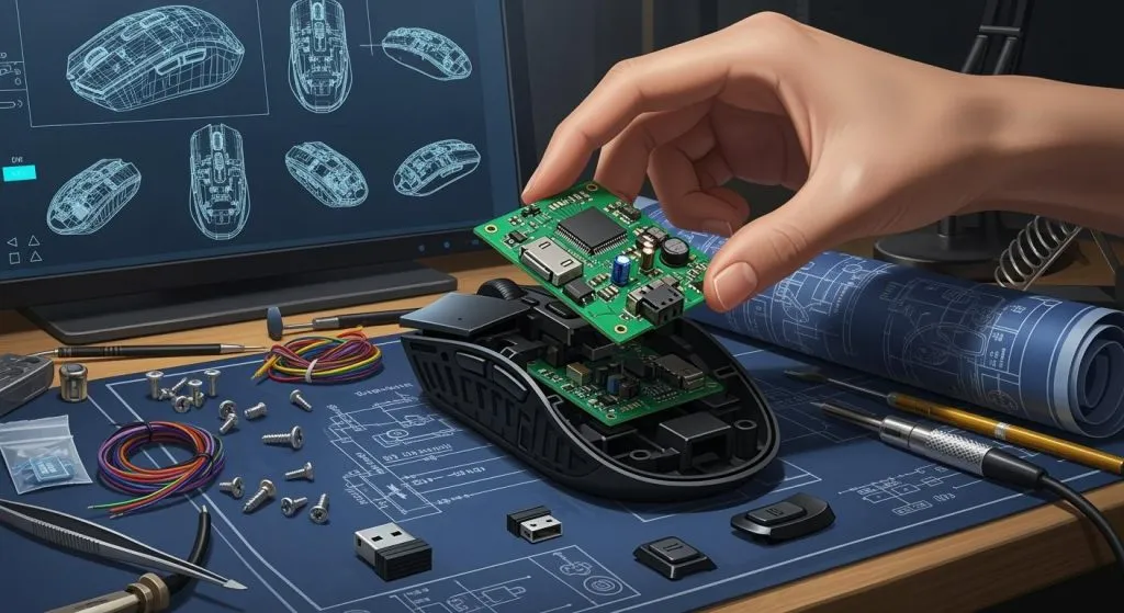
PCB Design and Simulation for AC Circuits
Simulation Tools
You can use simulation tools to help with ac analysis. These tools make your work easier and more correct. OrCAD PSpice lets you test your circuit before building it. You can check how your filter works with different signals. OrCAD PSpice gives you many ways to run ac analysis. You can see how your design works with analog and digital parts. This helps you find problems early and fix them.
Tip: Simulation results are close to real measurements. Most of the time, results match over 90%. Only about 10% is different.
You can use these tools to test filter designs. You can change values and see what happens fast. This saves you time and money. You do not need to build lots of test circuits. You can also follow industry rules in your design. This helps you avoid problems with electromagnetic interference. Good simulation tools help you make better choices for pcb design and analysis.
Reliability in AC Design
You want your ac circuit to last a long time. You can use reliability checks to test your design. Here is a table that shows some important checks:
Metric | Description |
|---|---|
MTTF | Mean Time to Failure, for things you cannot repair |
MTBF | Mean Time Between Failures, for things you can repair |
Thermal-cycle fatigue | Failure from heating and cooling cycles on solder joints |
Mechanical vibration | Failure from shaking or moving parts |
Shock failure | Failure from sudden impacts on solder joints |
Plated through-hole fracture | Breaks in the holes that connect layers in the PCB |
You can use smart design steps to make ac circuits stronger. Here are some ways to lower signal loss and stop interference:
Impedance control keeps signals steady and stops reflections.
EMI reduction uses good grounding and shielding to block noise.
Impedance discontinuity management stops signal problems, especially in fast filter circuits.
You should also follow spacing and alignment rules. This keeps your design safe and easy to build. When you use these steps, your filter design will work better and last longer.
You notice special things happen in ac circuits with resistors, capacitors, and inductors. Resistors let current and voltage reach their highest points together. Capacitors make the current reach its highest point before the voltage does. Inductors make the voltage reach its highest point before the current. If you learn about impedance, reactance, and phase, you can make better circuits. This helps you fix problems and improve how your circuits work. You can move power better and keep signals clear. Simulation tools and PCB design programs help you test ac circuits. You can see how voltage changes and check if your circuit will last. These tools help you make electrical systems that are safer and work better.
FAQ
What happens if you connect a resistor, capacitor, and inductor in one circuit?
You create a circuit that can filter signals. The resistor controls current. The capacitor and inductor add reactance. You can use this setup to study the frequency response of a circuit and see how signals change at different frequencies.
How does a high-pass filter work in a circuit?
A high-pass filter lets high-frequency signals move through the circuit. It blocks low-frequency signals. You often use this filter to remove unwanted noise. You can build a high-pass filter with a capacitor and a resistor.
Why do you need frequency analysis in AC circuits?
You use frequency analysis to see how a circuit reacts to different signals. This helps you find which signals pass and which get blocked. You can check if your circuit works well for music, radio, or other uses.
What is an oscillator, and why is it important?
An oscillator makes a repeating signal in a circuit. You use it to create clock signals, sounds, or radio waves. The design of oscillator circuits helps you control the timing and shape of these signals.
How does frequency affect the behavior of a circuit?
Frequency changes how capacitors and inductors act in a circuit. At high frequencies, capacitors let more current flow. Inductors block more current. You must test your circuit at different frequencies to see how it works.