Electric vehicle technology needs special pcb solutions for better safety and reliability. Engineers have more work as vehicle systems get harder to build. Multi-layer pcb designs and new materials are now needed for heat control and strength. Some common problems are high power, very hot or cold temperatures, and small spaces. Designers must solve issues like vibration, shock, rust, and electromagnetic interference. This helps each ev meet tough car rules and supports the fast growth of advanced vehicles around the world.
Key Takeaways
Make EV PCBs strong enough for lots of power and heat. Use special materials and layouts to keep them safe and working well.
Put parts in the right spots to control heat. This also helps stop interference and makes the board work better.
Use multi-layer and high-density PCBs to save space. This helps signals stay clear and supports complex EV systems.
Follow strict car rules and test the PCBs a lot. This makes sure they are good, safe, and last a long time.
Use new ways to build, like SMT and automated checks. This helps make EV PCBs that work well and do not cost too much.
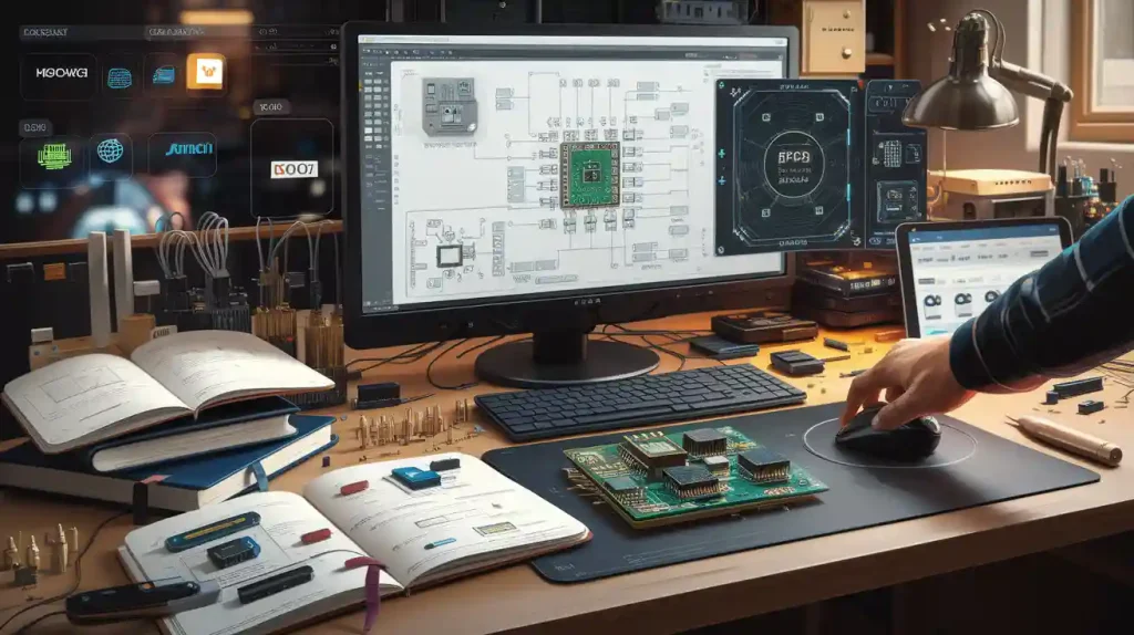
EV PCB Design
Power Density and High-Current Paths
Electric vehicle technology needs printed circuit boards that can handle lots of power and strong current. Engineers have to follow strict automotive pcb design rules for safety and reliability. Battery management system circuits need careful planning for high-current paths. This stops overheating and keeps resistance low.
Thermal management is very important. The right materials and layouts help move heat away. This keeps the battery and other parts safe.
Wide power and ground planes help lower current density and resistance. This makes conductivity better and cuts down on electromagnetic interference.
Routing should keep high-voltage and low-voltage signals apart, especially under transformers. This lowers the chance of interference and electrical problems.
Component layout should help heat move away and stop interference.
High-insulation materials and good spacing stop electrical breakdown. Protection circuits like overcurrent and short-circuit protection add more safety.
Electromagnetic compatibility design uses grounding and shielding for parts that might cause interference. Filters like LC and RC types help block high-frequency noise.
Tip: Always use fuses with ratings lower than the wiring and trace current. This protects the battery and system from harm.
Automotive pcb design for electric vehicles must solve these problems. This helps the boards meet strict car standards and work well every time.
Component Placement and Layout
Where you put components affects both heat and electrical performance in automotive pcb design. The battery management system needs smart layout choices to keep the battery cool and signals clear. Studies show that how engineers place parts changes heat flow and parasitic inductance in electric vehicle boards.
Do not group power parts too close. This stops hotspots and helps heat move away, making the board more reliable.
Put heat-making parts, like power transistors, near heat sinks or thermal vias. This helps control battery and system temperatures.
Make high-current paths short and wide. This lowers resistance and inductance, making electrical performance better.
Place high-current parts first. This makes sure traces are the right size and keeps parasitic effects low.
Keep power supply parts close together. Shorter traces mean less electromagnetic interference and fewer impedance jumps.
Make the loop area of high switching current paths small. Put current and return paths next to each other to cut voltage spikes and interference.
Separate circuits by what they do. Put analog control parts last to save space and keep signals safe.
Automotive pcb design rules suggest these steps. They help with routing, lower interference, and support modern battery management systems.
Signal Integrity and EMI
Keeping signal integrity in automotive pcb design is very important for electric vehicle safety and performance. High-voltage systems and wireless devices in EVs make strong electromagnetic interference. Engineers must use advanced rules to protect sensitive signals and keep things working right.
High-voltage powertrains and RF modules cause most interference in electric vehicle boards.
EMI shielding materials, like aluminum or copper, block or move electromagnetic fields away.
Grounding methods, like single-point grounding and multi-layer ground planes, stop ground loops and leakage.
Filtering, like low-pass filters and ferrite beads, blocks high-frequency noise. Decoupling capacitors near IC power pins keep voltage steady and block noise.
PCB design rules say to keep traces apart to lower crosstalk. Short traces act less like antennas. Put noisy parts away from sensitive circuits. Use multi-layer stackups with special ground and power planes for controlled impedance.
Note: Testing for EMC compliance is always needed. As technology changes, engineers must update their automotive pcb design to stop new interference and keep signal integrity.
Automotive pcb design for battery management systems and other EV uses must follow these rules. This makes sure the boards are safe, reliable, and work well.
Thermal Management in Electric Vehicle PCBs
Materials for Heat Dissipation
Thermal management is very important in electric vehicle PCB technology. Engineers pick materials that help move heat away from important circuits and battery systems. Copper and aluminum are great for heat sinks because they spread heat fast. Many battery management systems use thick copper layers, sometimes up to 20oz, to help spread heat and stop self-heating. Special FR-4 types and polyimide laminates can handle high heat and do not break down easily. These materials keep the battery safe and help the technology last longer.
Thermal vias under hot parts help move heat to inside layers or heat sinks. Conformal coatings, like silicone or polyurethane, protect the board from heat and other damage. Engineers often use a table to compare materials for good thermal management:
Material | Max Temp (°C) | Heat Conductivity | Common Use |
|---|---|---|---|
Polyimide | >250 | High | Battery, power PCBs |
Heavy Copper | >200 | Very High | Power, battery paths |
Aluminum | >150 | High | Heat sinks |
Tip: Always pick materials that fit the battery and technology needs for the best thermal management.
Design for Extreme Temperatures
Electric vehicle PCBs need to work in both hot and cold places. Engineers make changes to the design to keep them working well:
Pick high Tg laminates, like polyimide, and solder that can take high heat. Use parts and coatings that do not get damaged by heat.
Add heat sinks and thermal vias to move heat away from battery and power parts. Use thick copper layers to help spread heat better.
Make trace widths and spaces big enough for high currents. Build strong vias and match material types to stop stress and peeling.
Test boards by heating and cooling them many times. Check that they work well in all temperatures.
These steps help battery systems and technology stay safe and work well. Good thermal management makes sure materials and design choices protect electric vehicle electronics in any weather.
Materials for EV PCBs
High-Temperature Substrates
Engineers pick high-temperature substrates for electric vehicle pcb boards. These materials help the boards last in tough places. Polyimide is a top pick because it can take a lot of heat. It does not break down fast. FR-4 with high glass transition temperature (Tg) is also a good choice for many pcb boards. Ceramic substrates, like aluminum oxide, can handle even more heat and stay stable.
A strong substrate keeps the pcb safe during hot and cold cycles. It stops the board from bending or cracking. Engineers look at different materials before they decide. The table below lists some common choices:
Substrate Type | Max Temp (°C) | Key Benefit |
|---|---|---|
Polyimide | >250 | High flexibility |
High-Tg FR-4 | 150-180 | Cost-effective |
Aluminum Oxide | >300 | Superior stability |
Tip: Always choose the right substrate for the board’s heat needs. This helps the board work well for a long time.
Surface Finishes and Coatings
Surface finishes keep pcb boards safe from rust and help with soldering. Engineers use different finishes for this. ENIG gives a smooth surface and strong protection. HASL puts a layer of solder on copper traces to protect them. OSP uses an organic layer to stop the copper from rusting.
Coatings give extra protection. Conformal coatings, like silicone or acrylic, cover the whole board. These coatings block water, dust, and chemicals. Engineers pick coatings based on where the board will be used.
ENIG: Best for small, close parts.
HASL: Good for most uses and saves money.
OSP: Simple and better for the environment.
Good surface finishes and coatings help pcb boards last longer. They keep the boards working well in electric vehicles.
Automotive PCB Standards
Quality and Reliability Requirements
Automotive engineers must follow very strict rules. These rules make sure every circuit board is high quality. The IPC-A-610 Class 3 standard is the main rule for automotive PCB design. This rule explains how circuit boards should work in cars. It focuses on making them strong and able to last a long time. Engineers also use IPC-2221B to help with trace width, spacing, and layout. These rules help stop problems in tough places.
Boards in cars must work with lots of shaking, bumps, and big temperature changes. Reliability tests look for cracks, rust, and weak solder joints. The AEC-Q100 rule checks if electronic parts are good for cars. This testing makes sure each board helps keep people safe. Engineers write down every step to show they follow the rules.
Note: Using these rules helps engineers make cars safer and more secure.
Safety Certification
Safety certification is very important in automotive PCB design. ISO 26262 is the main rule for safety in car electronics. This rule explains how circuit boards help keep cars safe. Engineers must prove each board meets all safety and security rules.
Certification means lots of tests and checks. Inspectors make sure the board follows every rule. They look for things that could hurt the car or people. Passing these tests shows the board helps keep everyone safe.
Standard | Focus Area | Automotive Use |
|---|---|---|
IPC-A-610 | Quality inspection | All circuit boards |
ISO 26262 | Functional safety | Safety systems |
AEC-Q100 | Reliability testing | Electronic components |
IPC-2221B | Design guidelines | PCB layout |
Automotive engineers use these rules to keep drivers and passengers safe. Meeting these standards makes sure every automotive PCB design is safe, secure, and lasts a long time.
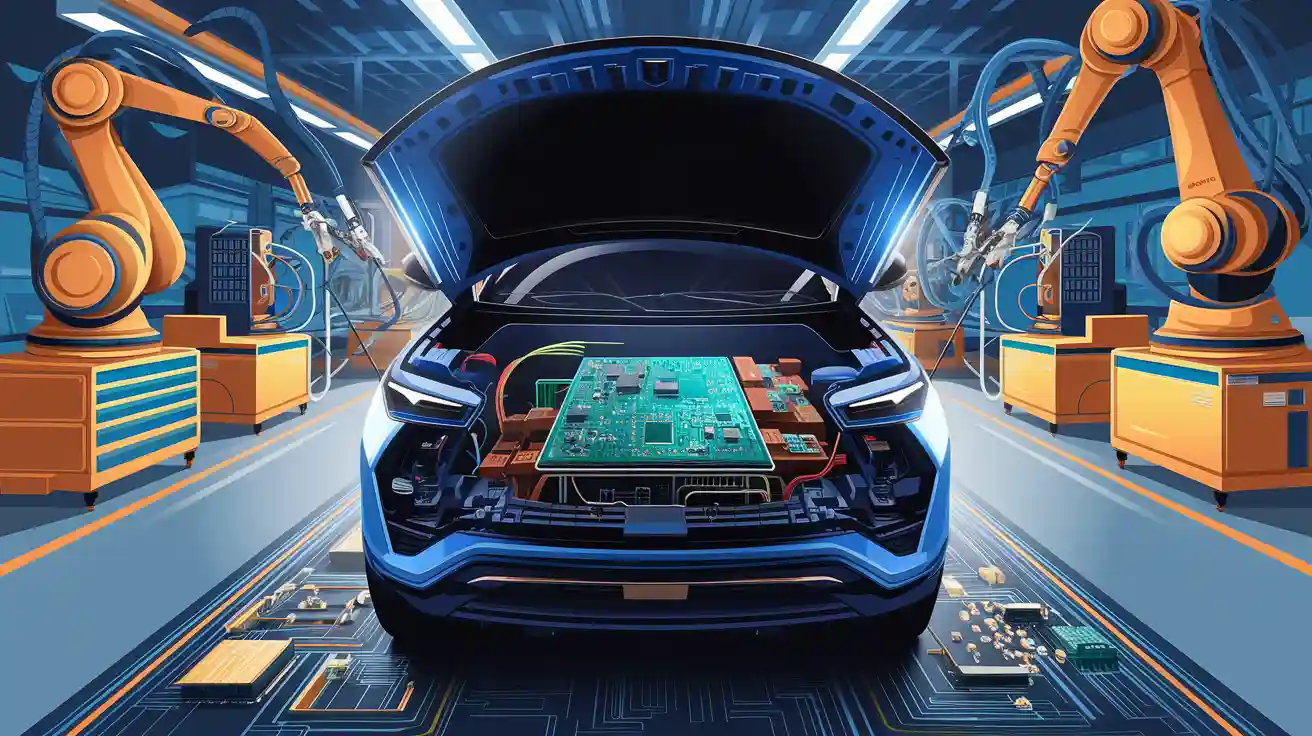
Manufacturing for Safe Electric Vehicles
SMT and Automated Assembly
Surface Mount Technology (SMT) and automated assembly are very important in making automotive PCBs. These methods help engineers make boards that are safe and work well in electric vehicles. SMT lets engineers put parts on both sides of the PCB. This makes the board smaller and lighter. Automated machines place and solder parts with great accuracy. This helps make fewer mistakes and keeps the boards the same every time.
The table below lists the main good and bad points of SMT and automated assembly for automotive PCBs:
Aspect | Benefits | Limitations | Solutions/Notes |
|---|---|---|---|
Performance & Cost | High performance; cost-effective components and assembly | N/A | SMT enables quick prototyping and high-volume production |
Design Flexibility | Supports hybrid SMT and through-hole designs; components on both sides of PCB; compact layouts | N/A | Enables complex multilayer PCBs and innovative layouts |
Stability & Durability | Enhanced PCB stability under vibrations and thermal cycling; 30% higher durability in harsh conditions | Solder joints may weaken under thermal stress | Use high-quality solder materials and stress testing |
Repairability | N/A | Small lead spacing complicates repairs; requires advanced inspection tools like X-ray or AOI | Invest in advanced inspection technologies; robust PCB design to reduce repair needs |
Component Suitability | Suitable for most components except high-heat or high-load ones | Unsuitable for components generating excessive heat or high electrical loads | Combine SMT with through-hole components for hybrid designs |
Assembly Precision | Automatic component alignment via solder surface tension; precise selective soldering | N/A | Advanced soldering techniques improve reliability |
Device Size & Weight | Enables compact, lightweight devices by mounting components on both sides | N/A | Ideal for space-constrained applications like EVs |
Electromagnetic Compatibility | Improved EMC due to lower lead inductance, reducing EMI | N/A | Meets regulatory standards enhancing product safety |
SMT helps save money and makes boards work better. Engineers sometimes use both SMT and through-hole parts together. This is helpful when some parts need to handle more heat or power.
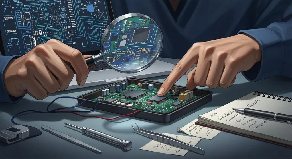
Inspection and Quality Control
Inspection and quality control make sure every automotive PCB is safe and works well. Automated Optical Inspection (AOI) checks for problems like parts in the wrong place or missing solder. AOI can find very small problems, even as tiny as 0.1mm. This helps engineers fix issues early and saves money by cutting down on rework.
AOI lowers the need for people to check boards by up to 40%. This makes building boards faster and cheaper.
Reflow soldering makes strong joints that work well for high-current systems.
Wave soldering is good for through-hole parts and gives strong connections for high-power uses.
Companies that do AOI, reflow, and wave soldering together help keep quality high and costs low.
Automotive PCB makers use these checks to keep electric vehicles safe. Quality control at every step helps the boards stay reliable and meet tough car industry rules.
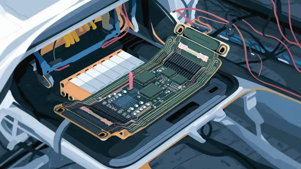
Compact and Multi-Layer EV PCBs
Miniaturization and Lightweight Design
EV engineers work to make boards smaller and lighter. They have problems when shrinking pcb size. High power and heat can hurt small boards. It is harder to control electromagnetic interference when parts are close. Fitting many parts and wires in small spaces is tricky.
High-power pcbs help manage more heat and current in tight spots.
New materials and good thermal management keep boards safe.
High-Density Interconnect (HDI) technology uses lasers and microvias. These let more circuits fit in less space and signals stay strong.
Automation helps, but making dense HDI boards needs careful planning.
Engineers use both off-the-shelf and custom parts. This mix helps meet function and long-term goals.
Tip: Engineers should always check if the pcb can handle power and heat before finishing the design.
Multi-Layer and High-Density Interconnects
Multi-layer boards are important in new ev systems. These boards let engineers fit more circuits and parts in a small space. This is needed in electric vehicles, where space and weight matter a lot. Multi-layer pcbs also make electrical performance better. Layers close together help signals move faster and make boards more reliable.
More layers give engineers extra options for hard circuit designs.
The layered setup helps lower electromagnetic interference and keeps things stable.
High-density interconnects let engineers build advanced boards for control units and other systems.
Real-world use in car control units shows these boards work well in tough places.
A table below lists the main benefits of multi-layer and high-density boards:
Feature | Benefit |
|---|---|
More layers | Higher circuit density |
Close layer proximity | Better signal performance |
Layered structure | Less electromagnetic noise |
Design flexibility | Supports complex systems |
Engineers use these boards to meet the strict needs of ev technology.
Electric Vehicle Charging PCBs
High-Power Circuit Design
Engineers make evc boards to handle strong currents and voltages. These boards use thick copper layers to carry more current. The thick copper also helps move heat away from important parts. The way the pcb is set up is very important. If you put hot parts far apart, it helps lower heat and electrical noise. Wide copper lines and thick solder masks cover the spaces made by heavy copper. This follows IPC rules for safety.
Materials with a high Comparative Tracking Index (CTI) let engineers put copper parts closer together. This makes the evc board smaller but still safe. Engineers use ways to control heat like heat sinks, airflow, and heavy copper inside the board. How much space you need depends on voltage. For example, tracks are 1 mm apart at 48V and 16 mm apart at 480V. Conformal coatings keep water and dust off the pcb. This makes the evc system work better and last longer.
Tip: Always check that the battery management system and evc boards follow IPC-SM-840 rules for solder mask thickness and insulation.
Isolation and Protection
Isolation and protection are very important for safe charging. Engineers use barriers like transformers and optocouplers to keep high voltage away from control circuits. This stops electric shock and keeps the battery safe. Protection devices like RCDs, fuses, and circuit breakers stop too much current or voltage from hurting the evc system.
Controlling heat is also important. Heat sinks, thermal pads, and sensors watch the temperature and can turn off the system if it gets too hot. Good grounding gives a safe path for extra current and helps with electromagnetic compatibility. Engineers follow IEC rules like IEC 61851 and IEC 61000 to make sure evc boards are safe and reliable everywhere.
A table below shows common ways to protect evc boards:
Protection Method | Purpose |
|---|---|
Isolation barriers | Stop electric shock |
RCDs and fuses | Stop too much current/voltage |
Thermal sensors | Watch and control heat |
Grounding | Safe path for extra current |
These steps help keep the battery, pcb, and evc system safe when charging an electric vehicle.
Digitalization in Automotive PCB Design
Simulation Tools
Simulation tools have changed how engineers design car boards. These tools let teams test ideas before making real boards. Engineers use digital models to see how circuits act in many situations. They can check for heat, signal loss, or electrical noise. This helps teams find and fix problems early. It saves time and money.
Many engineers use SPICE simulators to study circuits. They also use thermal software to see how heat moves on the board. Some tools help test for electromagnetic interference. These digital tools help engineers follow strict car rules. They also make sure the technology works well in real cars.
Tip: Teams should always use simulation tools before making a new board. This step helps avoid costly mistakes and keeps the technology safe.
Design for Testability
Design for testability is very important in car board design. Engineers plan the board so it is easy to test. Good testability helps find problems fast. This keeps the technology safe and reliable. In cars, safety and quality are most important.
Engineers add test points to the board. These points let machines check if circuits work right. They also use self-test features. These features help the board check itself for errors. Teams often use automated test equipment to make testing faster.
A table below shows common testability features in car technology:
Testability Feature | Benefit |
|---|---|
Test points | Easy to check circuits |
Self-test circuits | Finds errors quickly |
Automated testing | Saves time and improves quality |
Car engineers use these methods to make sure every board meets the rules. Good testability helps keep car technology safe and strong.
Engineers who make PCBs for electric vehicles must think about safety and reliability. They also need to follow the rules. New technology brings flexible and multilayer PCBs. High-frequency boards help with communication. Eco-friendly materials are now used more often. Car PCB design changes as new rules and technology appear. Groups like SimuTech help by giving advice, testing, and design tips. Teams can make safer and better EV and EVC systems by learning the latest rules and working with experts.
FAQ
What makes PCB design for electric vehicles different from regular automotive PCBs?
Electric vehicles use much higher voltages and currents. Their PCBs need to handle more heat and power than normal car boards. Designers pick special materials and smart layouts. This helps keep the boards safe and working well.
Why do engineers use multi-layer PCBs in electric vehicles?
Multi-layer PCBs help save space inside electric vehicles. They let engineers fit more complex circuits in small areas. These boards also help control heat and lower electrical noise. Signal quality gets better in advanced EV systems.
How do manufacturers test the quality of EV PCBs?
Manufacturers use Automated Optical Inspection, X-ray checks, and electrical tests. These tests help find problems early before the boards are used. Quality control makes sure every board meets strict car industry rules.
Which standards must EV PCBs follow for safety and reliability?
EV PCBs must meet IPC-A-610, ISO 26262, AEC-Q100, and IPC-2221B rules. These rules cover quality, safety, and reliability for car boards. Following these rules helps protect drivers and their vehicles.