You use the reflow soldering process to connect parts to a PCB. This method heats solder paste until it melts. The melted paste holds the parts in place. Many companies pick the reflow soldering process for PCBs. It works well with small parts and gives accurate results. It is also good for automation. The reflow soldering process has several steps. First, you apply solder paste. Next, you place the components. Then, you preheat the board. After that, you soak it. Next, you reflow the solder. Last, you cool the board. You must watch for defects and new technology. Problems like tombstoning or lifted pads can happen.
Here are some common defects you may see in the reflow soldering process:
Defect Type | Description |
|---|---|
Component Shift | Leads and pads do not line up because parts move during heating. |
Tombstoning | One end of a chip lifts up while the other stays soldered. This happens from uneven heating. |
Skipped Solder | No solder on a pad or lead. This can cause open circuits. |
Lifted Pad | Copper pads come off the PCB from too much heat or stress. |
Blowhole/Pinhole | Small holes in solder joints from trapped gas. These holes make the joint weaker. |
Contamination/Chemical Residue | Leftover chemicals can damage metal and cause circuit problems. |
Fractured Solder Joint | Solder joints crack from heat changes or shaking. |
Wire Breakage | Wires break at solder joints from bending or shock. |
Heat Loss | Solder joints do not get hot enough because heat leaves too fast. This stops proper soldering. |
Reflow Soldering Process in PCB Assembly
What Is the Reflow Soldering Process?
You use the reflow soldering process to attach parts to a pcb. First, you put solder paste on the pads. The paste keeps the parts in place before heating. Next, you set the parts on the board. You make sure they match the pads. Then, you heat the pcb in a reflow oven. The solder paste melts and connects the pads and parts. After cooling, you check the board for problems. This process helps you make strong and good solder joints.
Main Steps in the Reflow Soldering Process:
Put solder paste on pcb pads with a stencil.
Place parts on the board and line them up.
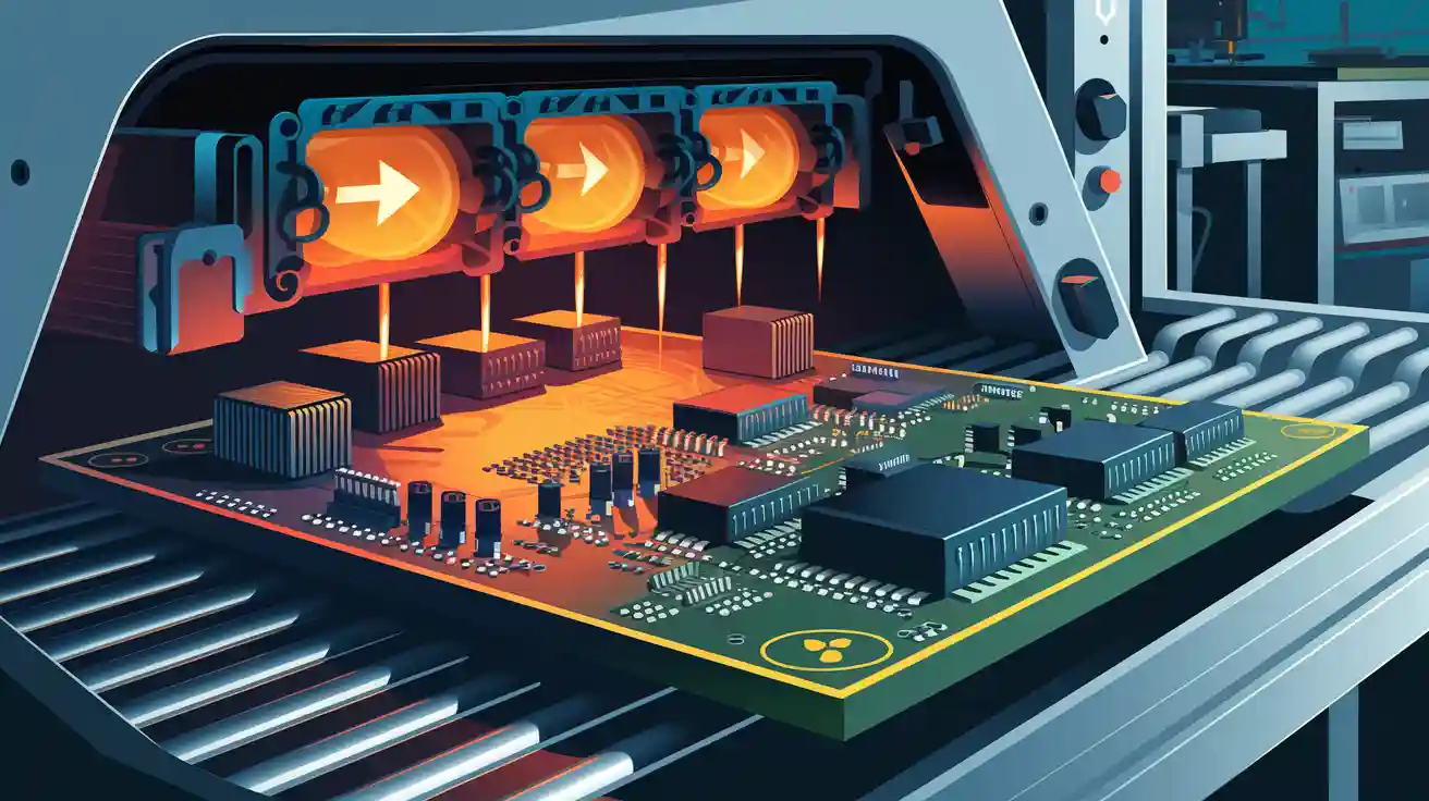
Heat the pcb in a reflow oven to melt the solder paste and join the parts.
Check the board for problems and make sure it is good.
Why Use Reflow Soldering for PCBs?
You pick the reflow soldering process for pcbs because it works well with small and delicate parts. This method lets you control the heat better, so you protect the parts. Reflow soldering is best for surface mount technology (SMT), which is used a lot in new pcb assembly. When you look at reflow soldering and wave soldering, you see some big differences:
Aspect | Reflow Soldering | Wave Soldering |
|---|---|---|
Working Principle | Parts go on a pcb and solder paste is heated in a reflow oven. | pcbs with parts move to a wave soldering machine where solder waves are used. |
Usage Scenarios | Used mostly for SMT assembly. | Used mainly for through-hole (THT) assembly. |
Soldering Needs | Gives better welding with controlled heat. | Makes a lot of heat, which can hurt sensitive parts. |
Soldering Complexity | Needs more complex machines and controls. | Easier setup, just change welding settings. |
Advantages | Great for SMT, less heat shock, and fewer workers needed. | Saves time, costs less, and makes strong solder joints. |
Key Benefits
When you use the reflow soldering process, you get many good things:
You get neat and even solder joints because the heat and cooling are controlled.
You can make lots of pcbs at once, so you work faster and better.
Machines do the work, so people make fewer mistakes and you fix less.
Good reflow soldering makes smooth joints that are strong for electricity and holding parts.
By changing the heat and using nitrogen, you get fewer problems and better boards.
These good things make the reflow soldering process the best choice for new pcb assembly.
Stages of the Reflow Soldering Process
The reflow soldering process has many steps. Each step helps make strong connections on your pcb. If you follow every step, you can stop problems and make your assembly better.
Solder Paste Application
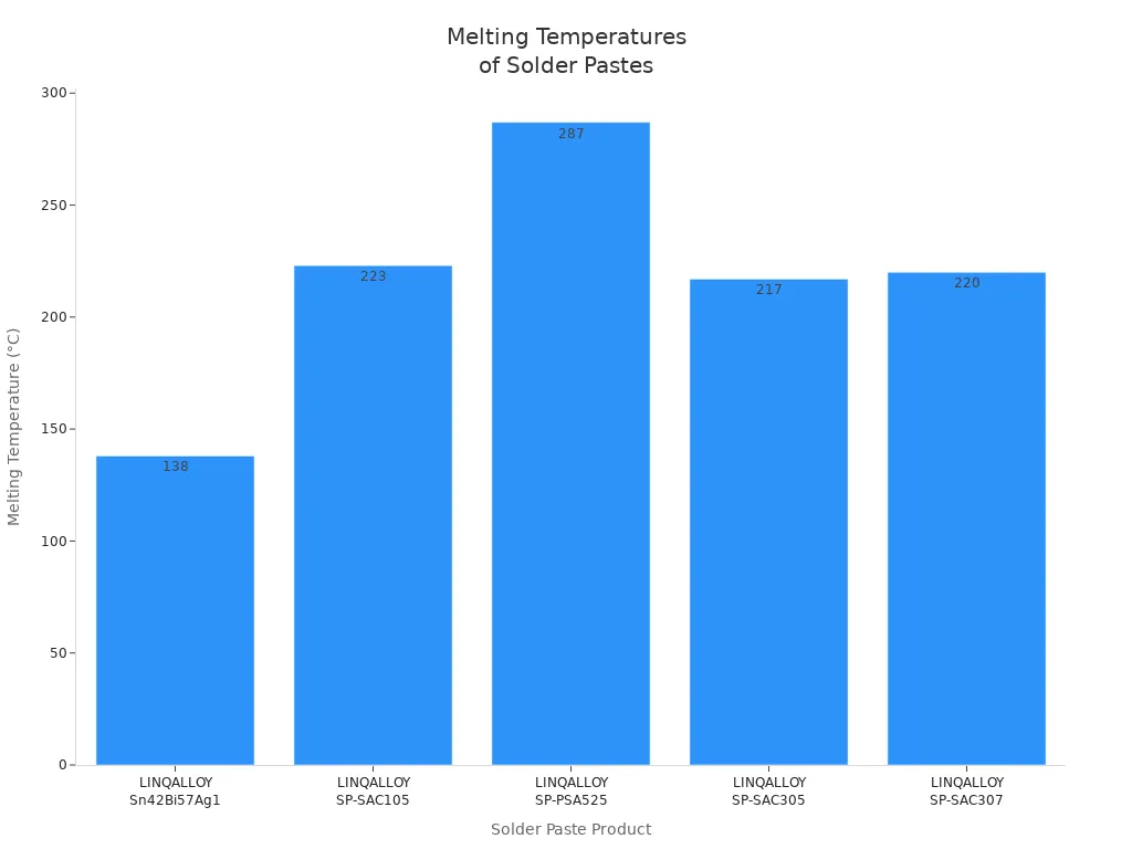
First, you put solder paste on the pcb. The paste has tiny metal bits and flux. It holds surface mount devices and other parts before heating. You use a stencil to put paste only on the pads you want. The kind of solder paste you pick changes how things go and how good the result is. Here is a table with some solder paste products and what they do:
Product | Description | Alloy | Particle Size Distribution | Viscosity (mPA.s) | Melting Temperature | Shelf Life |
|---|---|---|---|---|---|---|
LINQALLOY Sn42Bi57Ag1 | Low eutectic solder paste for LED Assembly | Sn42Bi57Ag1 | Type 3, 4 | – | 138°C | 6 months at 5°C |
LINQALLOY SP-SAC105 | Pb-free solder paste designed for Surface Mount Technology (SMT) | SAC105 | Type 3, 4, 5 | 200 | 223°C | 6 months at 5°C |
LINQALLOY SP-PSA525 | High lead solder paste designed for clog-free dispensing die attach processes | Pb92.5Sn5Ag2.5 | Type 3, 4, 5 | 130 – 170 | 287°C | 6 months at 5°C |
LINQALLOY SP-SAC305 | Pb-free solder paste designed for Surface Mount Technology (SMT) | SAC305 | Type 3, 4 | 160 – 230 | 217°C | 6 months at 5°C |
LINQALLOY SP-SAC307 | Pb-free solder paste designed for Surface Mount Technology (SMT) | SAC307 | Type 3, 4, 5 | 190 – 230 | 220°C | 6 months at 5°C |
You can also choose different flux types for your solder paste:
Rosin based fluxes use natural rosin and need special cleaners.
Water-soluble fluxes use organic stuff and wash off with water or other cleaners.
No-clean flux leaves almost nothing behind and is best for clean places.
Picking the right solder paste and flux helps you get good joints and strong soldering.
Component Placement on PCB
After you put on the solder paste, you add the parts to the pcb. You must be very careful here. If you put a part in the wrong spot, you can get weak joints or problems. Most factories use machines to place surface-mount parts and other pieces. These machines are very exact. For example, the placement system should be right within ±0.001″. The X-Y tolerance is usually ±0.2mm. You also need to make sure each part’s leads cover the pads. The IPC-A-610 and J-STD-001 rules say you need at least half overlap, and sometimes up to three-fourths for boards that must last a long time.
Even a tiny mistake, like moving a part by 0.1 mm, can cause bad soldering or short circuits. You must check every part’s direction and position to keep your pcb working right.
Preheating and Soaking
Next, you put the pcb in the reflow oven for preheating and soaking. You slowly warm up the board and parts to get ready for soldering. This step stops thermal shock and lets the flux work. The heat you use depends on your solder paste. Here is a table with normal ranges:
Solder Type | Preheating Temperature Range | Soaking Temperature Range |
|---|---|---|
Leaded | 25°C to 150°C | 150°C to 200°C |
Lead-Free | Up to 180°C | 180°C to 220°C |
You usually set preheat between 120°C and 160°C. The soak stage goes from 160°C to 180°C. For lead-free soldering, you may use preheat from 150°C to 190°C and soaking around 217°C. If you control the heat well, the solder paste melts evenly and you avoid problems.
Reflow Stage
The reflow stage is the most important part. You heat the pcb until the solder paste melts and makes solid joints between pads and parts. The temperature profile is very important here. You must reach the right top temperature and hold it for the right time. Too much heat can hurt parts or cause cracks. Not enough heat means the solder does not melt all the way, and you get weak joints.
The top temperature and how long you hold it change how good your solder joints are.
Holding too long can break down materials and make failures more likely.
You must watch the heat closely to get strong and safe joints.
Cooling
After reflow, you need to cool the pcb. Cooling makes the solder joints hard and strong. You must control how fast you cool to stop thermal shock and keep parts safe. The best cooling rate is 3–6 °C per second. If you cool too slow, you get big grains in the solder, which makes joints weaker. If you cool too fast, you can bend parts or crack the joints.
Tip: Keeping a steady cooling speed helps you get strong solder joints and good pcbs. Always watch the cooling step to stop problems.
Every step in the reflow soldering process is important for making your pcb assembly work well. If you pay attention to solder paste, part placement, heat control, and cooling, you can make strong joints and stop common problems.
Advantages for PCBs
Precision and Automation
Reflow soldering helps you place parts very accurately. Machines put solder paste only where it is needed. This is good for boards with lots of tiny parts. The oven keeps the heat steady, so parts do not get too hot or cold. This helps stop mistakes and makes strong connections. You can add small parts with thin leads without making solder bridges. Automation uses pick-and-place machines to set parts on the board. These machines work quickly and do not make many errors. Special inspection machines look for problems. This helps you know your board is made well.
Solder paste goes exactly where it should for tiny parts
Steady heat stops stress and lowers mistakes
Pick-and-place machines put parts in the right spot
Inspection machines find problems early
Scalability
Reflow soldering lets you make many boards fast. If you need thousands of boards, machines help you work quickly. You can use this process for big batches or just a few boards. When you make more boards, each one costs less. Here is a table that shows how reflow helps you make more boards:
Scalability | Good for 10,000+ boards | Works for small batches or under 1,000 boards |
|---|---|---|
Production Speed | Faster with machines | Slower, often done by hand |
Cost per Unit | Lower when you make a lot | Higher when you make only a few |
Flexibility
Reflow soldering works for many kinds of board designs. It is great for Surface Mount Technology. This lets you put parts right on the board. You can use different types of packages in one run. This makes reflow good for new electronics that need careful work. You can build boards with parts on both sides and mix many types of parts in one process.
Tip: Reflow soldering lets you design boards with lots of parts and tight spaces.
Reliability
Reflow soldering makes strong and safe joints. The oven keeps the heat just right to make good connections. You can test your board by using thermal shock tests. This checks if the joints stay strong when the temperature changes. A thin layer at the joint makes it stronger. If the layer is too thick, the joint can break. Reflow soldering helps keep the layer thin, so your board lasts longer.
Thermal shock tests check if joints are strong
Thin layers at joints make them better
Steady heating and cooling make tough connections
Defect Prevention in Reflow Soldering
You want your pcb to last a long time. You need to stop defects during reflow soldering. This part explains how to control heat, pick solder paste, check your boards, use nitrogen, and fix problems. Each step helps you make strong connections and better boards.
Temperature Profiling
You must watch the temperature at every step. Good temperature control stops defects and keeps your pcb safe. You use special tools to check heat on the board. Here are some tips:
Slowly raise the heat during preheating. Keep the ramp rate between 0.5°C and 2.0°C per second. This stops thermal shock and starts the flux working.
Hold the soak stage at 150°C to 180°C for 60-120 seconds. This keeps heat even on the pcb.
Set the reflow stage peak 20-30°C above the solder’s melting point. Keep Time Above Liquidus (TAL) between 30-90 seconds.
Cool the board at 2-4°C per second. This helps make strong joints.
Use good thermal tools to get the right heat data.
Check more than one board to see if ovens are different.
Watch and change profiles often to keep results steady.
Always read the solder paste datasheet for special heat needs.
Tip: Careful temperature control helps you stop defects and keeps your pcb working well.
Solder Paste and Flux
You need to pick the best solder paste and flux for your pcb. The type of solder paste changes how well soldering works and how many defects you get. Look at the alloy, powder type, and microstructure. Spherical powder with low oxide makes better joints. Match the solder paste to your board and pad size. Type 3 to Type 6 powders work for different pad sizes and help stop bridging.
Many things in solder paste printing can change defect rates. Here is a table that shows what matters most:
Level | Factor Description |
|---|---|
1 | Stencil opening shape from how it is made |
2 | Solder paste matching |
3 | Waiting time effects |
4 | Squeegee material choice |
5 | Printing machine settings |
6 | Reflow soldering settings |
You also need to pick the right flux. Rosin-based flux needs special cleaning. Water-soluble flux washes off with water. No-clean flux leaves almost nothing behind. The right solder paste and flux help you get strong joints and fewer defects.
Inspection Methods
You must check your pcb after soldering to find problems early. You use different ways to look for defects. Here is a table that shows the most common ways:
Inspection Method | Description |
|---|---|
Visual Inspection | People look for defects by eye. |
Automated Optical Inspection (AOI) | Cameras and software find missing solder and bad parts. |
X-ray Inspection | Finds hidden problems like voids and solder bridges inside the pcb. |
Functional Testing | Checks if the pcb works right after assembly. |
AOI uses cameras to find missing parts and bad joints. X-ray looks inside the pcb to find cracks and holes. Functional testing checks if the pcb works. You use these ways to catch problems before they get worse.
Controlled Atmosphere
You can use nitrogen during reflow soldering. Nitrogen helps you make better joints and stronger boards. Here is a table that shows the benefits:
Benefit | Description |
|---|---|
Oxide formation | Nitrogen lowers oxides during soldering. |
Wettability improvement | Solder flows better and makes stronger joints. |
Reduced defects | You get fewer problems like bad solder and bridging. |
Flexibility in flux selection | You can use more flux types because the air is controlled. |
Post-cleaning requirements | You spend less time cleaning after soldering. |
Enhanced reliability | Soldering in nitrogen makes your pcb last longer. |
Note: Using nitrogen in reflow soldering helps you make strong joints and lowers defect rates.
Common Defects and Solutions
You may see problems like tombstoning, bridging, and voids in your pcb. You can fix these by following good steps. Here is a list of solutions:
Make the stencil openings 80-90% of pad size and match the pcb layout.
Control solder paste amount. Use a stencil thickness of 0.1-0.15 mm for small parts to stop too much paste.
Change the reflow profile. Use a slow ramp-up rate (1-3°C per second) in preheat to stop fast solder melting.
Check part placement. Use good pick-and-place machines for exact placement.
Balance the reflow profile. Set preheat at 150-180°C for 60-90 seconds to keep heat even.
Make pad design the same. Make sure pads under parts are the same size and shape.
Check solder paste on pads. Use SPI tools to make sure paste is even on both pads.
Make placement better. Calibrate pick-and-place machines to put parts within ±0.05 mm.
You follow these steps to stop common defects and keep your pcb working well. Good control of solder paste, heat, checking, and nitrogen helps you make strong joints and better boards.
Innovations in the Reflow Soldering Process
New technology keeps changing how people make pcbs. There are big improvements in reflow soldering now. Some new things are vacuum reflow, smart ovens, and making parts smaller. These changes help you make better connections. They also make boards last longer. Smaller surface-mount parts are used more often.
Vacuum Reflow
Vacuum reflow uses a special oven chamber. This chamber takes out air and gases during soldering. It helps lower voids in solder joints to only 1-2%. With vacuum reflow, joints get stronger. Heat moves better through the board. This is important for cars and airplanes. Your pcb can last longer and handle more stress. Fewer weak spots mean better performance.
Tip: Vacuum reflow helps you get strong and reliable connections. It is great for surface mount devices.
Smart Ovens
Smart ovens give you more control over soldering. They use sensors to watch temperature all the time. Problems are found early with these ovens. You can see how smart ovens stop defects in the table below:
Fault Type | Impact on Quality | Prevention Tips |
|---|---|---|
Heater Failure | Bad soldering, damaged components | Check heaters, use real-time alerts |
Conveyor Calibration Drift | More defects, like bridging | Calibrate often, track conveyor speed |
Thermal Spill Issue | Inconsistent soldering, pcb damage | Watch temperature zones, avoid big temperature gaps |
Airflow Inconsistencies | Unreliable soldering, more failures | Clean filters, measure heat transfer |
Cooling System Failure | More damage, costly rework | Keep cooling clean, monitor cooling zones |
Smart ovens keep temperature steady within ±2°C. This gives you good results and fewer problems. You save time and money by fixing issues early.
Miniaturization for PCB Assembly
Making parts smaller has changed pcb assembly. You now use tiny pads and small surface-mount parts. Solder deposits are smaller too. Sometimes, only one solder grain forms. This can make joints weaker. To fix this, you cool faster, above 2°C per second. New solder paste formulas also help.
More surface mount devices fit on each pcb.
Solder paste spots are smaller, so control must be precise.
Pick and place machines use two lanes to go faster.
Operation temperatures are higher, especially with lead-free solder.
Solder paste chemistry has changed for high heat.
You can build more complex boards and work faster. These changes help you meet the needs of new electronics. Every millimeter matters now.
Note: The global market for reflow ovens is growing quickly. This shows how important these new ideas are for making pcbs.
You use reflow soldering to make strong PCBs for new electronics. This process lets you control heat very well. It helps you get solid solder joints and fewer problems.
Careful temperature control keeps parts safe from damage.
Good solder paste and flux help parts stick better.
Checking boards and using nitrogen make them work longer.
Smart ovens and machines help stop mistakes.
Electronics are getting smaller and harder to build. You should pick reflow soldering to solve these problems and make products last.
FAQ
What is the main purpose of reflow soldering?
You use reflow soldering to attach electronic parts to a board. This process melts solder paste to make strong connections. It helps you build reliable and high-quality boards for many devices.
Can you use reflow soldering for both sides of a PCB?
Yes, you can use reflow soldering on both sides. You first solder one side, then flip the board and repeat the process. This method works well for complex printed circuit boards.
How do you prevent defects during reflow soldering?
You control the temperature profile and use the right solder paste. You also check the board with inspection tools. These steps help you avoid common problems like tombstoning or bridging.
Why is nitrogen used in reflow soldering?
You use nitrogen to reduce oxidation during soldering. This gas helps you get cleaner joints and fewer defects. Nitrogen also improves the strength of the solder connections.
What is the difference between reflow and wave soldering?
You use reflow soldering for surface-mount parts. Wave soldering works best for through-hole parts. Reflow uses a heated oven, while wave soldering uses a wave of molten solder.