You face special problems when you work with humanoid robotic PCB design. Advanced pcb systems run humanoid robots. They help with real-time processing and use many voltage rails. The table below shows how humanoid needs are different from regular pcb needs:
Aspect | Humanoid Robotic PCB Requirements | General PCB Requirements |
|---|---|---|
Power Requirements | Many voltage rails (1.8V to 24V+) | Usually one voltage rail |
Sensor Integration | Many sensors, supports many protocols (UART, I2C, etc.) | Few sensors |
Environmental Conditions | Must handle vibration, heat, and EMI | Normal conditions |
Power Management | Advanced systems with battery management | Simple power management |
Processing Capabilities | Real-time processing with fast control loops | Regular processing |
You need special materials and flexible circuits for strong humanoid pcb systems. The humanoid robotics field is growing quickly. The market may reach $6.5 billion by 2030. It could grow by 138% each year. Sensors and AI make humanoid pcb design different from regular robotics work.
Humanoid Robotic PCB Needs
Space and Form Factor
Designing pcbs for humanoid robots is tricky. You have to fit circuit boards into small, curved, or moving parts. These robots need boards that are not always rectangles. Sometimes, you stack boards on top of each other. Flexible pcbs help fit electronics into arms, legs, and joints. The table below shows some problems and how to fix them:
Challenge | Solution |
|---|---|
Space Constraints | Use compact layouts, multi-layer pcbs, and flexible boards. |
Irregular Shapes | Non-rectangular designs to fit anthropomorphic structures. |
Stacked Boards | Vertical stacking or flexible pcbs for compact spaces. |
Humanoid robot makers must think about what the market wants. They need to make strong printed boards that fit inside the robot’s body. The market for humanoid pcb keeps getting bigger as more companies join.
High-Frequency Materials
Special materials are needed for humanoid robotics. These materials help pcbs work with fast signals and in tough places. DuPont Pyralux TK lets robots move in more ways. Panasonic FELIOS R-F775 helps make smaller, better printed boards. Some materials help with heat and last longer in hard conditions. The table below lists important materials and what they do:
Material | Performance Benefits |
|---|---|
DuPont Pyralux TK | Enables complex movements, enhancing agility and adaptability in robots. |
Panasonic FELIOS R-F775 | Contributes to miniaturization, allowing for compact yet high-performing designs. |
N/A | Improves thermal stability and resistance to harsh environments, ensuring reliability. |
You have to pick the best materials for each part of your robot. Market research shows that better materials make better robots. Companies that use new materials do better in the market.
Sensor and AI Integration
Sensors and AI modules help robots learn and react. You need to connect lots of sensors to your pcb. You also need AI chips that work fast. The SOM-6884 module lets you upgrade without starting over. It uses AI-ready processors, like the 13th Gen Intel Core, for smart computing. You get fast connections with PCIe Gen4 and USB 4.0. These features help your robot sense, think, and act quickly.
You can add new sensors or AI modules when needed.
You keep your design open for future changes.
You meet what both makers and users want in robotics.
The humanoid robot pcb market keeps growing as more companies use better materials and smart modules. By picking the right pcb, materials, and ways to connect things, you help make robots better.
Humanoid Robotics PCB Design
Design Steps
First, you find out what your robot needs to do. You write down all the requirements. Next, you use EDA software to make a schematic. This helps you see how each part connects. Then, you work on layout and routing. You put parts in place and draw lines for connections. You think about heat and how the robot moves. After that, you check your design with a rule check. This helps you catch mistakes early. Now, you choose and get the right materials. The next steps are imaging, stacking, drilling, and plating. You add solder paste and put parts on the board. Machines help solder the parts in place. You look at the board and test if it works. At the end, you finish putting it together and pack the pcb.
Special Considerations in Humanoid Robotics PCB Design
You have to think about how the robot moves. Humanoid robots bend and twist a lot. Your design must fit inside arms and joints. Flexible circuits and high-frequency materials are often used. These choices help your pcb last longer and keep working well.
Design Challenges
Designing humanoid robotics pcbs is hard. You need materials that can bend and handle moisture. You must watch the bending radius so the pcb does not break. Flexible pcbs are harder to put together than stiff ones. You must place each part carefully. High-performance designs cost more money. You need to balance quality and price.
Key Differences from Traditional PCB Design
Humanoid robots move and flex more than regular ones. Regular pcbs do not move much. Humanoid designs need to bend and handle stress. You use more sensors and need better power control. Your pcb must deal with more heat and shaking.
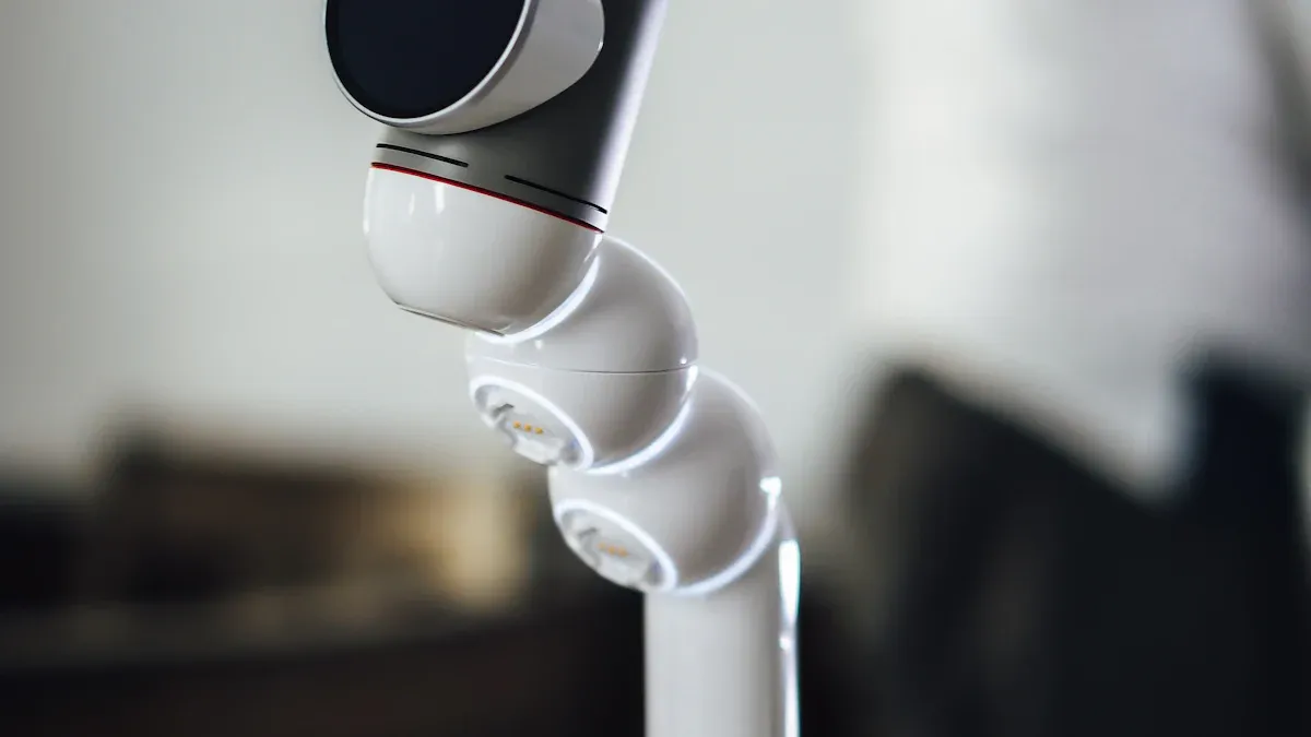
Flexible Circuits
Flexible circuits help robots move like people. They let you put sensors and actuators in moving parts. You can use lots of sensors for hard jobs. Flexible circuits can bend over 200,000 times. This makes them great for robots that move a lot.
Application | Benefit |
|---|---|
Integration of sensors and actuators | Lets joints move naturally |
High-density sensor arrays | Helps robots do complex things |
Flexibility and durability | Survives over 200,000 bends for active robots |
Signal and Power Management
You need to keep signals clear and power steady. Use special traces for fast signals. Keep weak signal lines away from strong power lines to stop EMI. Multilayer boards help you set up ground and power planes. Use voltage regulators and DC-DC converters for the right voltages. Add current sensors to watch power use and stop overloads. Good signal and power control keeps your pcb safe and working well.
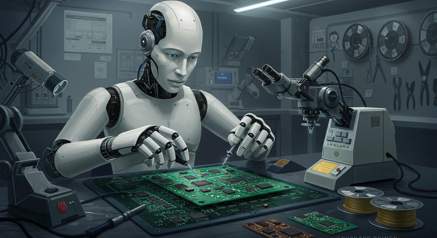
Humanoid Robotics PCB Assembly
AI-Driven Placement
AI-driven placement is changing how we build humanoid robotics pcb assemblies. Machines use smart programs to put small parts in the right spot. This helps place parts with very high accuracy. It is important for memory modules and AI processors. You get better signals and make fewer mistakes. Robotic SMT makes the work faster and more dependable. These systems do hard jobs that people cannot do by hand.
AI-driven placement lets you control where parts go.
You make pcb manufacturing faster and better.
You lower mistakes and keep robots working well.
3D Circuit Integration
3d circuit integration is needed for new humanoid robotics pcb assembly. This way, you can stack and shape boards for small or curved spaces. Circuits can wrap around joints or fit inside arms and legs. Multilayered and metal core pcbs help with heat and safety. You use special assembly steps to connect sensors, actuators, and processors in tight spots. This makes humanoid robots stronger and more flexible.
Tip: 3d circuit integration saves space and helps manage heat in your humanoid robot designs.
Testing Methods
You must test every humanoid robotics pcb assembly to make sure it works. Many tests help find problems and keep robots safe. Optical and X-ray checks find things you cannot see. Robots with cameras look for soldering and placement mistakes. Flying probe testing checks circuits without special tools. High voltage stress tests find hidden problems that could cause trouble later.
Testing Method | Description | Benefits |
|---|---|---|
Flying Probe Testing | Uses moving probes to test points with software. | Good for small to medium numbers of boards. |
High Voltage Stress Test | Finds isolation problems with high-voltage pulses. | Finds defects other tests may miss. |
You also test for open and short circuits. You measure resistance and capacitance. You check for polarity mistakes and tiny shorts. You look for phase differences. These steps help you find problems early and keep your pcb assembly strong.
The high voltage stress test is key for finding isolation problems. You send high-voltage pulses between signal lines. This test finds issues that other tests might not see. These advanced tests help protect your humanoid robots from failing.
Stable Connections
Stable connections are needed in every humanoid robotics pcb assembly. Robots move, bend, and twist a lot. You need strong solder joints and good connectors. Flexible circuits help keep connections safe when parts move. Special materials and designs stop wires from breaking. Metal core pcbs help with heat and keep connections strong. You check each connection during building to make sure your robot works in tough places.
Stable connections keep robots safe and working.
You stop signal loss and power problems.
You help your humanoid robotics pcb assembly last longer.
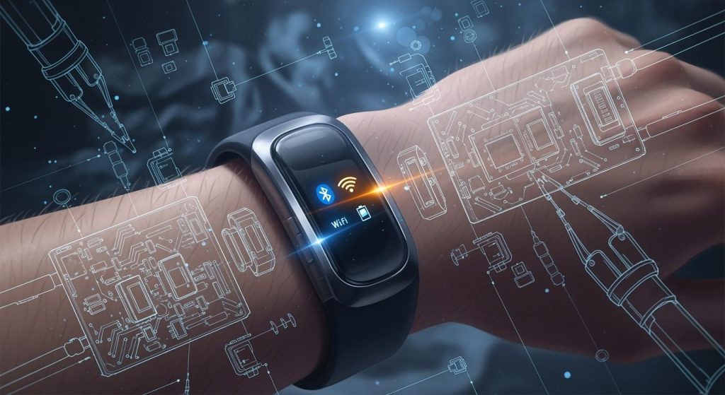
IoT and Emerging Tech
IoT Connectivity
IoT is changing how people design and use pcb systems in humanoid robots. IoT lets robots talk to other devices and share information. This helps robots make better choices and act faster. You need strong connectors to join motors, sensors, and processors. Good connections help your pcb work well and keep robots safe. AI works with IoT to help robots think on their own. When you build strong hardware, your robots can work in many places.
Connectors link hardware parts so robots can move and sense.
IoT lets robots share data and learn from what is around them.
AI and IoT together help robots make their own decisions.
Strong connections support motors, sensors, and processors for better work.
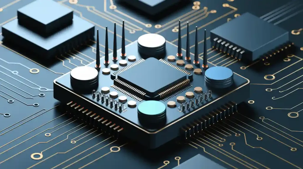
GaN Devices
GaN devices help make humanoid robots faster and more efficient. GaN stands for gallium nitride. It works better than silicon in many ways. You get smaller and lighter boards that fit in tight spaces. GaN helps your pcb handle more power and heat. This means robots last longer and use less energy. The table below shows why GaN is a good choice for robotics pcb design.
Advantage | Description |
|---|---|
High electron mobility | You get fast operations and quicker switching speeds. |
Wide bandgap | Your pcb can handle higher voltages and stay reliable. |
Excellent thermal conductivity | Your boards manage heat better, so robots stay safe. |
Miniaturization capabilities | You make smaller and lighter devices for compact robots. |
Energy efficiency | Robots use less power and work longer before charging. |
Future Trends
You will see new changes in humanoid robotic pcb design and manufacturing. IoT will keep growing, so robots will connect with more devices. GaN devices will be used more in robotics, making pcbs smaller and stronger. Flexible circuits will help robots move in new ways. Makers will use AI to improve how they build and test robots. New materials will help pcbs last longer and work better. You need to watch these changes to stay ahead in robotics and pcb making.
Tip: Keep learning about new pcb technologies and materials. This helps you build better humanoid robots and be a leader in robotics manufacturing.
Verification in Humanoid Robotic PCB
Verification checks if your pcb works safely in every robot. You need to test both hardware and software. This step helps you find problems before using the robot. You must use strong tests and follow important rules. Good verification keeps your robot from failing and keeps people safe.
Verification Objectives
Ensuring Functional Integrity
You want your pcb to work the right way. Each part must do its job. You check if signals move right and power flows well. You look for open circuits or shorts before making the board. Design reviews and rule checks help you find mistakes early. High quality means your robot will move and react as you want.
Meeting Safety and Compliance Standards
You must follow safety rules in robotics. These rules keep people and machines safe. Many groups make these rules, like OSHA, ISO, and ANSI. You need to check if your pcb meets these rules before making it.
OSHA makes rules to lower health and safety risks at work in the United States. OSHA also wants companies to train and teach workers to keep work safe and healthy.
Here are some important standards for humanoid robotics:
Standard/Regulation | Description |
|---|---|
ISO 10218 | Sets rules for industrial robot safety. |
ISO 13849 | Focuses on safety parts of control systems. |
ANSI/RIA R15.06 | Makes sure collaborative robot safety is the same in the U.S. |
CSA Z434 | Covers collaborative robot safety in Canada. |
ISO 13482 | Is for personal care and service robots. |
You also need to follow rules from groups like the FAA, FCC, FDA, and privacy laws.
Validating Sensor and AI Integration
Sensors and AI modules help your robot sense and think. You must check if these parts work together. You test if sensors send the right data and if AI chips process it fast. You make sure your pcb can handle many sensors and smart modules. This step keeps your robot smart and safe.
Verification Methods
Simulation and Modeling
You use simulation tools to test your pcb before building it. These tools show how signals move and how heat spreads. You can find problems early and fix them in your design. Modeling helps you save time and money.
In-Circuit Testing (ICT)
In-circuit testing checks each part on your pcb. You use probes to test connections and look for shorts or open circuits. ICT helps you find problems that could stop your robot from working. This method is very important for complex, multi-layered designs.
Functional Testing
Functional testing checks if your pcb does what you want. You run the board and see if it controls motors, sensors, and AI chips. You look for errors in real time. This step makes sure your robot can move, sense, and react as planned.
Environmental and Stress Testing
You test your pcb in tough conditions. You shake it, heat it, and cool it. You check if it works after many bends and twists. Environmental and stress testing helps you see if your pcb will last in a real robot. You want your board to survive vibration, heat, and EMI.
Challenges in Verification
You must keep high quality in your pcb for proper robot work.
You need to lower risks, especially in safety jobs.
You must review your design and check for open circuits or shorts before making it.
Complexity of Multi-Layered Designs
Multi-layered pcbs make checking harder. You have more connections and more places for mistakes. You need strong tests to check every layer. Design rule checks help you find hidden problems.
Real-Time Data Processing Validation
Humanoid robots need fast data processing. You must test if your pcb can handle real-time signals from sensors and AI chips. You look for delays or errors that could slow down your robot.
Integration of Flexible and Rigid Circuits
You often use both flexible and rigid circuits in humanoid robots. You must check if these parts work together. You test if connections stay strong after many bends. This step helps your pcb last longer in moving robots.
Best Practices for Verification
Best Practice | Description |
|---|---|
Collecting robust reliability data | Needed for future standard alignment beyond old ways. |
Implementing redundant safety control systems | Needed to override high-level autonomy using strong sensors. |
Following established safety standards | Follow ISO 13849 and ANSI/RIA rules for robot safety. |
Early Verification in the Design Cycle
Start checking early. You catch mistakes before they get big. Early checks save time and money.
Automated Test Systems
Use automated test systems to check your pcb. Machines can test faster and find more errors than people. Automated systems help you keep high quality in every board.
Continuous Feedback and Iteration
Keep testing and improving your pcb. Use feedback from each test to make your design better. Continuous checks help you build safer and stronger robots.
Tip: Humanoid robotic pcbs need more testing than general robotics. You must use in-circuit testing, functional testing, and even X-ray checks to make sure every part works. General robotics pcbs may not need such strict checks.
验证
You need to make sure your humanoid robot PCB works as planned. Verification means you check every part and every step. You want your robot to move, sense, and think without errors. If you skip this step, your robot may fail or even become unsafe.
Tip: Always test your PCB before you use it in a robot. This helps you find problems early.
You can use different ways to verify your PCB:
Visual Inspection: Look at the board. Check for missing parts or bad solder joints.
Automated Testing: Use machines to test circuits and connections. Machines find small mistakes that you might miss.
Simulation: Try out your design on a computer. See how signals move and how heat spreads.
Functional Testing: Run the board with motors and sensors. Watch if everything works as it should.
Environmental Testing: Put your PCB in hot, cold, or shaky places. Make sure it still works.
Here is a table to help you remember the main verification steps:
Step | What You Check |
|---|---|
Visual Inspection | Parts, solder, and board shape |
Automated Testing | Circuits, shorts, and open lines |
Simulation | Signal flow and heat |
Functional Testing | Motors, sensors, and AI chips |
Environmental Test | Heat, cold, and vibration |
You should keep records of your tests. Write down what you find. If you see a problem, fix it and test again. Good verification helps you build safe and smart robots. You can trust your PCB when you follow these steps.
You can make better humanoid robots by using good pcb design steps. Break big jobs into smaller tasks to help with assembly. Think about people’s needs to make building safer. The table below lists ways to keep getting better:
Strategy | Description |
|---|---|
Hierarchical Task Decomposition | Splits hard jobs into easy steps. |
Human-Centric Design | Puts people first for safer building. |
Proactive Integrated Design | Uses smart talk for better teamwork. |
New materials, AI, and IoT help make stronger pcbs for humanoid robots. Keep learning about new robotics tech to make sure your pcb works well and your robots are ready for what’s next.
FAQ
What makes humanoid robotic PCBs different from regular PCBs?
Humanoid robotic PCBs use flexible circuits and special materials. They also have many sensors. These features help robots move, bend, and think. Regular PCBs do not need to handle so much movement. They also do not do as many hard tasks.
How do you test a humanoid robotic PCB?
You look at the board with your eyes. You use machines to check for mistakes. You try out your design on a computer. You run tests with motors and sensors. You also test with heat and shaking. These steps help you find problems early.
Why do humanoid robots need flexible circuits?
Flexible circuits fit inside arms, legs, and joints. You can bend and twist them many times. This helps your robot move like a person. It also keeps the connections strong.
What materials work best for humanoid robotic PCBs?
You should use DuPont Pyralux TK and Panasonic FELIOS R-F775. These materials help your PCB last longer. They handle heat and support fast signals. They also make your robot safer and more reliable.
Can you upgrade sensors and AI modules easily?
Yes! You can add new sensors or AI chips when you want. You do not need to change the whole PCB. Open designs and smart modules help you upgrade as technology gets better.
Tip: Always keep your PCB design open for upgrades. This helps your robot stay smart and ready for new jobs.