Making and copying a wireless intercom PCB means creating and duplicating the circuit board that runs a wireless intercom. You need to know these steps to make custom intercoms or fix problems in current designs. Each step needs care, from picking parts to testing the finished product. Copying can help with learning or repairs but has ethical concerns. Always respect ownership rights and use copying wisely to stay out of legal trouble.
Key Takeaways
Pick the correct parts for your wireless intercom PCB. This helps with clear sound and less noise.
Use tools like KiCad or Eagle to make clean layouts. Good layouts improve signal strength.
Follow rules when copying PCBs to stay out of trouble. Respect others’ work and rights.
Test your PCB carefully to check it works in all conditions. Make sure it meets quality rules.
Begin with free designs to learn about intercom systems legally.
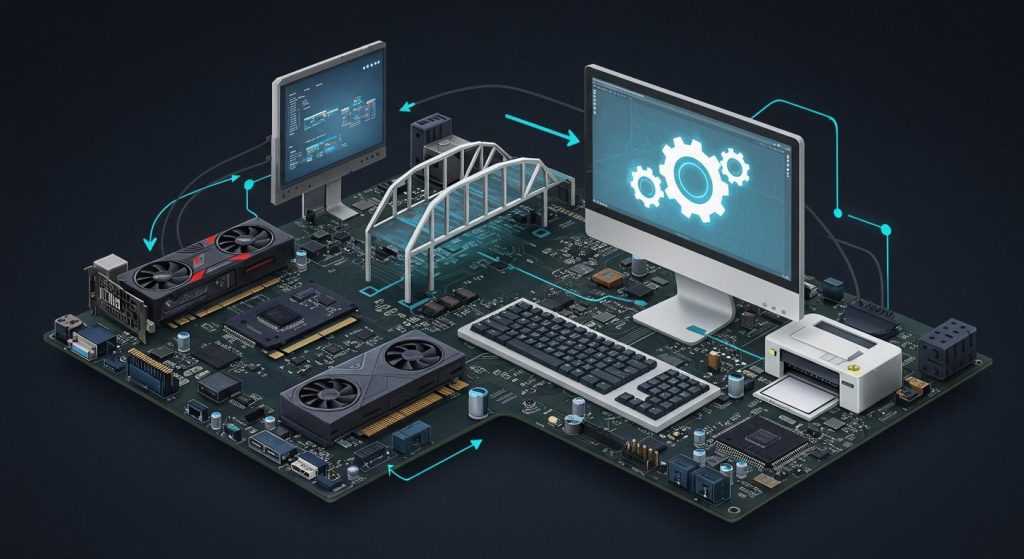
Designing a Wireless Intercom PCB
Key parts and features for a wireless intercom PCB
When making a wireless intercom PCB, pick the right parts. Each part is important for how the system works. For example:
Part Type | What It Does | How It Helps |
|---|---|---|
Power Amplifiers | Makes signals stronger for long-distance communication. | Keeps communication strong and clear in the intercom system. |
Low Noise Amplifiers (LNAs) | Improves weak signals while reducing noise for better reception. | Helps keep signals clear in noisy places. |
Switches & Filters | Manages signal paths and frequencies for smooth connections. | Makes it easier to handle communication channels in the system. |
These parts help the intercom PCB handle tasks like sending and receiving sound. To make a good intercom, choose parts that improve sound quality and reduce noise.
Circuit design and plans for a 2-way analog intercom
Designing a circuit for a 2-way analog intercom takes several steps. First, decide what the system needs, like sound input/output and range. Use a co-design method to combine physical and electrical rules in your plan.
Design Method | What It Does |
|---|---|
Co-design Method | Combines physical and electrical rules to guide the design process. |
System Interconnect Model | Creates a model to check if the design will work and guide the process. |
Parasitic Circuit Model | Estimates or finds models for parts to study signal behavior. |
For a 2-way analog intercom, use parts like the LM386 amplifier for clear sound. Add a DPDT switch to switch between talking and listening. This helps the base station and other units communicate smoothly.
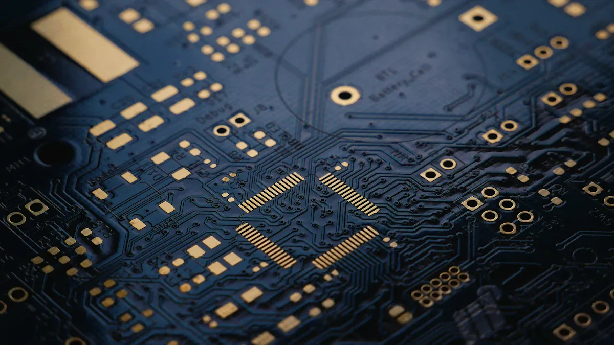
PCB layout and tools for custom intercoms
The PCB layout affects how well your intercom works. Use tools like KiCad or Eagle to design the layout. These tools help place parts neatly and reduce signal problems.
Simulation tools are also important. For example, a subtractor can cancel sidetone, and coupling capacitors keep signals steady. These tools ensure clear sound even in tough conditions.
When designing wireless intercom PCBs, think about adding features like ethernet. This can make your system more useful and dependable.
Manufacturing a Wireless Intercom PCB
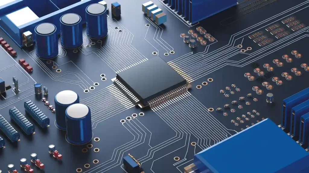
Picking materials and making wireless intercom PCBs
Choosing good materials is key for a strong intercom PCB. The materials must work well with high-frequency signals. Important factors include dielectric constant (Dk) and dissipation factor (Df). These show how well a material sends signals.
Material No. | Df Rank | Dk Rank | Electrical Rank |
|---|---|---|---|
5 | 1 | 2 | 1 |
8 | 2 | 3 | 2 |
3 | 3 | 4 | 3 |
6 | 4 | 1 | 4 |
4 | 5 | 5 | 5 |
7 | 6 | 6 | 6 |
2 | 7 | 7 | 7 |
1 | 8 | 8 | 8 |
Material No. 5 is the best choice for intercom PCBs. It works well at high frequencies like 10GHz and 15GHz. It also reduces signal loss when used with smooth copper foil.
Making the PCB involves stacking materials like FR4 or Rogers laminates. Copper traces are added, and the circuit design is etched. The copper layer’s thickness is important for keeping signals clear.

Building and testing to ensure quality
How you build the PCB affects its performance. Get parts from trusted suppliers to avoid fake ones. Use machines to place parts accurately and quickly. For soldering, use reflow for surface parts and wave soldering for through-hole parts.
Testing checks if the PCB works well. Automated Optical Inspection (AOI) and X-ray Inspection find mistakes in assembly. Functional tests check sound clarity and signal range. Environmental tests mimic tough conditions like heat and shaking to ensure durability.
Quality Check | What It Does |
|---|---|
Trusted Suppliers | Ensures parts are real and high-quality. |
Inventory Management | Keeps enough parts ready to avoid delays. |
Pick-and-Place Machines | Speeds up and improves part placement. |
Soldering Methods | Uses reflow for surface parts and wave soldering for through-hole parts. |
Inspection Tools | AOI and X-ray find assembly errors. |
Functional Testing | Checks if the PCB works in real situations. |
Environmental Testing | Tests the PCB in extreme conditions like heat and vibration. |
By following these steps, your intercom PCB will work well and last long, even in tough conditions.
Cloning a Wireless Intercom PCB
Ethical considerations and legal implications of cloning
Copying a wireless intercom PCB can help you learn, but it has rules. You must follow intellectual property laws. Copying without permission can cause legal trouble. Always check if the design is protected by patents or copyrights.
Using cloning to learn or fix old systems is usually fine. But selling copied designs without approval is wrong. Ask yourself: “Am I using this to learn or to steal?” Following the law helps you make a positive impact in electronics.
Tip: Use open-source designs first. They let you learn safely without breaking rules.
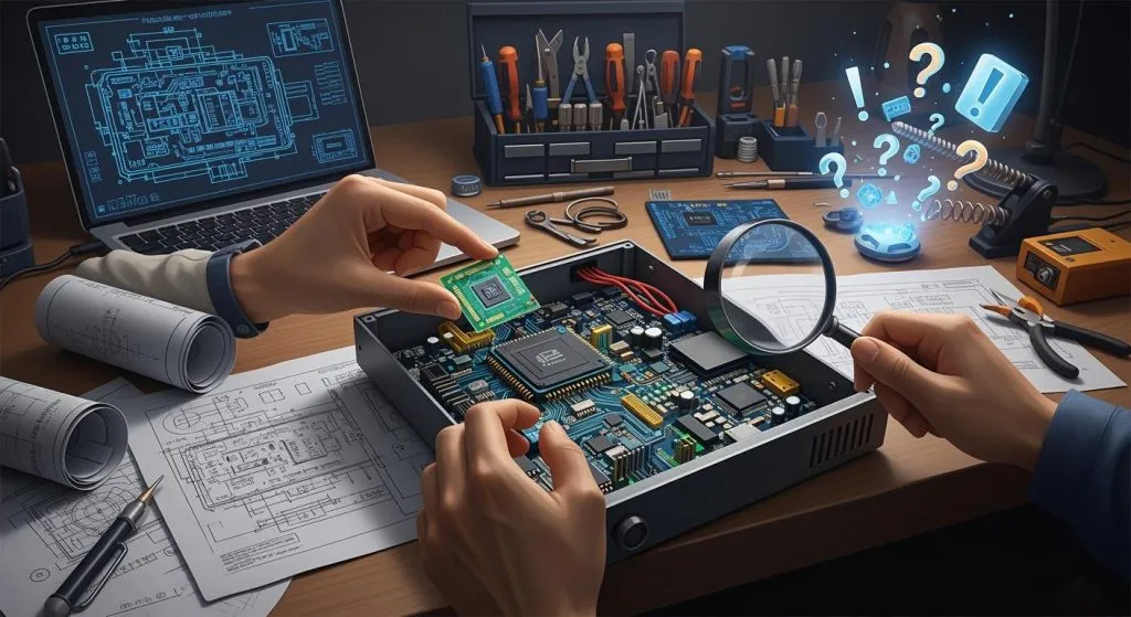
Reverse engineering techniques for a 2-way analog intercom
To reverse engineer a 2-way analog intercom, study its parts. Look at the PCB layout and find key components like amplifiers and switches. Use tools like a multimeter to trace how signals move.
Then, draw a diagram to show how the circuit works. Focus on features like half duplex communication, where talking and listening happen one at a time. Write down all details carefully for accuracy.
Reverse engineering takes practice to get better. It teaches you how good intercom systems are made.
Challenges and troubleshooting in cloning wireless intercom PCBs
Cloning a wireless intercom PCB can be tricky. Sometimes, schematics are missing or unclear. You might need to test and figure out the circuit yourself. Signal problems like noise or weak signals can also happen.
To fix issues, use simulation tools to test your design first. Check for mistakes like wrong part placement or bad soldering. If the PCB doesn’t work, review your diagram and layout again.
Cloning isn’t just copying; it’s about learning and improving. Solving these problems helps you build a better intercom system.
Making, building, and copying a wireless intercom PCB needs planning. Picking good materials and testing are very important steps. Following rules when copying protects ideas and helps create new ones. Begin with open-source designs to learn without breaking laws. Use programs like KiCad or Eagle to design layouts neatly. Talk to users to know what they need and make it better. Do surveys to find problems and improve features. Check often and try different ideas to make communication easy and clear. This keeps your intercom system simple and useful.
FAQ
What is the difference between full duplex and half duplex in intercom systems?
Full duplex lets you talk and listen at the same time. Half duplex only allows one action—either talking or listening. Full duplex makes communication smoother and easier for intercoms.
Can I add an ethernet connection to my wireless intercom PCB?
Yes, you can add ethernet to your intercom PCB. It makes the system more reliable and connects it to networks. This allows features like remote control and monitoring.
Why is full duplex important for wireless intercoms?
Full duplex allows talking and listening without switching modes. It makes conversations flow naturally without interruptions. This is helpful in places needing clear and constant communication.
What tools can help with designing a full duplex intercom PCB?
Use programs like KiCad or Eagle to design PCBs. These tools help create layouts for full duplex systems. Simulation tools also reduce noise and improve signal quality.
How do I troubleshoot issues in a full duplex intercom system?
Check the PCB layout for mistakes first. Use simulation tools to find signal problems. Make sure amplifiers and filters work properly. Test the system in real situations to fix errors.