Design for manufacturability (DFM) has become a necessary skill for PCB designers
Design for Manufacturability (DFM) integrates CAE (Computer Aided Engineering), CAD(Computer Aided Design), CAPP(Computer Aided Process Planning), and CAM (Computer Aided Manufacturing) with manufacturability analysis, ensuring manufacturing factors are considered at the design stage. From the aspect of focus: Design for manufacturability, this includes: During production process a structured analysis is done, and flow charts are made; it is necessary not only for particular departments to check but also crosswise among departments Unnecessary steps should be dropped, where possible and operations reviewed. Analyze manufacturing capabilities and limitations: This involves creating structured analyses and data flow diagrams of production processes, reviewed by relevant teams. Unnecessary operations are eliminated and processes are reviewed. Ensure manufacturability and quality: This includes testing designs for assemblability, testability, maintainability, and overall quality of new components and their assembly relationships. Main Contents of DFM Implementation 1. Establishing DFM Specifications Making a comprehensive DFM specification includes ·Aligning with the
Electronic Component Packaging Overview
Chip component packaging is a critical aspect of semiconductor device manufacturing. With the rapid development of technology, especially in SMT (Surface-Mount Technology), there are numerous packaging forms used in the electronics industry. Some packaging types, such as chip capacitors and resistors, have standardized sizes, while others, especially IC parts, are continuously evolving. Traditional pin packaging is gradually being replaced by new generations of packaging forms like BGA (Ball Grid Array) and Flip Chip. Common Chip Resistor Package Types There are 9 commonly used packaging sizes for chip resistors, represented by two types of size codes: imperial (inches) and metric (millimeters). The codes consist of 4 digits, where the first two represent the length, and the last two represent the width of the component. Here’s a breakdown of the common chip resistor packages: Imperial Code Metric Code Length (L) Width (W) Height (t) a (mm) b (mm) 0201 0603 0.60±0.05 0.30±0.05
How to Use DFM to Reduce PCB Manufacturing Costs?
There are many aspects to the cost of PCBA manufacturing. The core components mainly include the materials for the PCB bare board, the cost of SMT processing, and the cost of components. In addition to these core components, several other processes directly impact the cost of PCBA. Some of these factors are often overlooked, including other materials, testing, labor, assembly, design and PCB process optimization, and SMT patch process optimization. Affecting the Cost of the Bare Board (PCB) Part Board CostDifferent types of boards come with varying costs, depending on material and design specifications. Drilling CostThe number of holes and the size of the hole diameter directly impact the drilling cost. More holes or larger diameters will increase the cost. Process CostThe process requirements of the board, such as specialized coatings or complex designs, lead to different production difficulties, resulting in varying prices. Labor, Water, Electricity, and Management CostsThese costs
DFM (Manufacturability) Design of PCB Silkscreen
PCB Silkscreen are also known as “silk screen” in the industry. PCB silk screen can be seen on general PCB boards, so what are the functions of PCB silk screen? 1. Identifying Electronic Components As we all know, there are countless electronic components. The silk screen Silkscreens on the PCB board are used to identify which electronic components are placed on each pad. 2. SMT Assembly SMT assembles patches through silk screen Silkscreens. PCB silk screen Silkscreens help the factory identify the position numbers of each component during the patching process. 3. Product Repair PCB silk screen Silkscreens are also helpful for product repairs. They guide the repair personnel in locating the corresponding position of each component. 4. Product Identification In addition to component identification, PCB silk screen Silkscreens can include other essential information, such as product name, manufacturer logo, UL marks, production cycle codes, and other identification codes. DFM Design
PCB Manufacturing File Formats
The engineering files used in PCB production include PCB files, ODB++ files, Gerber files, and EXCELLON files. Among these, Gerber files are used for photoplotting to produce film for exposure and screen printing. EXCELLON format files serve as drilling and milling program files, facilitating hole drilling and shaping. PCB files must be converted into Gerber and EXCELLON formats to be utilized in production. On the other hand, CAM software for PCB manufacturing can directly read ODB++ file data. PCB Data Files What is a PCB File? PCB files are design files saved from EDA (Electronic Design Automation) software. These files cannot directly serve as production tool files since manufacturing equipment cannot recognize PCB file formats. All PCB data files saved from EDA software need to be converted into Gerber format for production. Gerber files are the primary file format used in manufacturing equipment, although certain inspection tools may support the
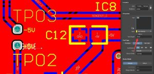
The Severity of Insufficient Spacing of Assembled Electronic Components
SMT assembly chip processing is with the development of electronic products to the development of high precision, fine pitch direction, and SMT chip processing components of the minimum pitch design needs to be able to ensure that the PCBA pads are not easy to short and also take into account the maintainability of the components. Consequences of insufficient component-to-component spacing; One of the pins of the Bottom side connector on the PCB is too close to the next via hole, resulting in a short circuit between the pin and the via hole, and the PCB is burned. The distance between the component mounting hole and the pad is too small. The through-hole itself is directly connected to the pad, and there is no solder resist between the hole and the pad and the spacing is not suitable for the wave soldering process, or the welding parameters, such as speed and
The Importance of Global DFM Awareness for PCB Design
The analogy that “ICs are just smaller versions of multilayer PCBs” is not entirely without merit. As processes become more differentiated between PCB manufacturers and assemblers, PCB design may begin to embrace some of the same philosophies used by the IC design industry to deal with escalating complexity. DFM manufacturability analysis is especially important in complex PCB design and manufacturing processes. 1. Purpose-oriented design concept The key to a DFM free design is to match the design rules and constraints to the capabilities of the PCB manufacturing and assembly supplier. Once the design rules and constraints are established, they become the review conditions that need to be followed at all times to ensure that the design is manufacturable. Problems that arise during design are easiest to identify and correct during the design phase. Having DFM awareness at the design stage can pay huge dividends. Identifying manufacturing issues during initial design
Solve the Problem of PCB SolderMask Vias
PCB solder mask ink according to curing method , solder mask ink has photosensitive developing ink , there are heat-curing thermosetting inks, There are also UV light-cured UV inks. , and PCB hard board solder mask ink, FPC soft board solder mask Ink , and aluminum substrate solder mask ink , aluminum substrate ink can also be used on ceramic boards. Vias are generally divided into three categories: blind vias, buried vias, and through holes. “Blind vias” are located on the top and bottom surfaces of printed circuit boards. It has a certain depth and is used to connect the surface circuit and the inner circuit. , Circuit The “through hole” passes through the entire circuit board. , from the top layer to the inner layer and then to the bottom layer. Vias in PCB solder mask processing , Common via processes include: via cover oil, via plug oil, via window opening, Resin plugging, electroplating filling, etc. , each of the five processes has its
Severity of Inadequate Component to PCB Board Edge Spacing
Consequences of insufficient component-to-board edge spacing; Devices that are too close to the edge may interfere with the operation of automated assembly equipment, such as wave or reflow soldering machines. Devices that are too close to the edge may be damaged during the panelling of the board at the end of the manufacturing process. This damage may be intermittent and difficult to detect and debug. The higher the device, the greater the potential for interference with the assembly equipment. Devices such as large electrolytic capacitors, for example, should be placed further away from the board edge than other devices. To avoid these problems, here are some general guidelines for device-to-edge clearance A general guideline for device clearance around the edge of the printed circuit board is 2.5 mm, which will provide enough room for test fixtures and most assembly operations. Panel V-grooves: For PCBs that will be v-grooved for punching, the device
Printed Circuit Board Design Highlights
PCB Design Preparation 1. Information to be provided with hardware C ●Accurate schematic diagrams, including paper and electronic files and error-free network tables. ● An official BOM with component codes. the hardware engineer should provide a DATASHEET or physical object for components that are not in the package library and specify the order in which the pins are defined. ● Provide a general layout of the PCB or the location of important units and core circuits. Provide PCB structure diagrams, which should indicate the shape of the PCB, mounting holes, positioning components, prohibited areas, and other relevant information. 2. Basic design requirements before design ● High-current components and networks of 1A or more. ● Important clock signals, differential signals, and high-speed digital signals. ● Analog small signals and other easily disturbed signals. ● Other special required signals. 3. Special request notes ● Differential distribution lines, networks requiring shielding, characteristic impedance
PCB Definition of Various Layers in Circuit Board Design
For beginners, there are many “layers” in PCB circuit boards, and many beginners are easily confused by the various PCB layers when learning PCB design. Below, let the engineer summarize the definition of various layers in PCB design for you to help beginners better understand and master. There are many different definitions of the specialized terminology of EDA software. The following is an explanation of the possible meanings of the words. Mechanical: Generally refers to the dimensional marking layer of a plate machine. Keep layer: Defines areas where wires, holes (via) or parts cannot be routed. These restrictions can be defined independently of each other. Top overlay: defines the silkscreen characters on the top layer, which are the part numbers and some characters and silkscreen frames that we usually see on the PCB. Bottom overlay: defines the bottom layer of silkscreen characters, which is the component number and some characters we normally see
PCB Assembly Has an Impact on SMT Assembly!
Why do PCBs need to be stencilled? PCBs are assembled to meet production requirements. Some PCB boards are too small to meet the fixture requirements, so they need to be assembled together for production. In order to improve the soldering efficiency of SMT. Only need to pass through the SMT once to complete the soldering of multiple PCBs. In order to improve cost utilization. Some PCB boards are shaped, so assembling PCB boards can utilize the PCB board area more efficiently, reduce waste and improve cost utilization. PCB Imposition Method The gong board with V-cut is suitable for boards with devices on the board edges, which can’t be assembled without spacing, and adopt the form of assembling with process edges. Add process edge V-CUT processing at both ends, leaving spacing in the middle of the gong to facilitate the welding of components, otherwise the devices on the edge of the
One of the Causes of Component Soldering: Manufacturable Design Specifications for the Hole in the Disk
What is hole-in-pad? Hole in the disk refers to the hole in the pad, the pad for the SMD disk, usually refers to 0603 and above SMD and BGA pads, usually referred to as VIP (via in pad). Plug-in holes in the pad can not be called a hole in the disk, because plug-in holes in the pad need to insert components to be soldered, all plug-in pin pads have holes. With the development of electronic products to light, thin, small direction, the PCB board is also pushed to the high-density, difficult to develop, so the size of the components are gradually becoming smaller. For example: BGA components of the package is small, the pin spacing becomes smaller. Pin spacing is small, then the package inside the pin is difficult to get out of the line, you need to change the layer of perforation out of the line. In the
Never Underestimate PCB Half-Hole Boards
Never Underestimate PCB Half-Hole Boards What is a PCB half-hole? Half vias are rows of holes drilled along the boundaries of a PCB for production purposes. When the holes are plated with copper, the edges are trimmed off so that the holes along the border are halved. The edges of the PCB look like a plated surface with copper inside the holes. What is the purpose of half-holes? Modular PCBs are basically designed with half vias, mainly for ease of soldering, small module size and functional requirements. Usually, a half-hole is designed in the PCB single edge of the hole, in the gong shape gong half, leaving only half of the hole in the PCB, commonly known as a half-hole. Design for manufacturability of half-hole plates 1. Minimum half-hole Minimum half-hole process manufacturing capacity is 0.5mm, the premise is that the hole must be in the center of the profile line,
Leading New Thinking in Industry – How the Meaning of DFM Will Evolve
Preface: In the complex PCB design and manufacturing process DFM manufacturing analysis is particularly important. DFM Design for Manufacturing, Design for manufacturability (DFM) DFM role is to improve the manufacturing process of the product. Today’s DFM is the core technology of parallel engineering, because design and manufacturing are the two most important links in the product life cycle, parallel engineering is the beginning of the design should be considered when the product manufacturability and assemblability and other factors. Therefore, DFM is the most important support tool in parallel engineering. The key of DFM is to analyze the processability of the design information, evaluate the manufacturing rationality and suggest the improvement of the design. DFM combines with CAX, PDM, DFX, etc. to form the Design for Life Cycle (DFLC) technology. DFX refers to DFA (Design for Assembly), DFD (Design for Disassembly), DFQ (Design for Quality), DFI (Design for Inspection), and DFE (Design for
How to Solve the Problem of Mismatch Between Bom Material and Pad
What is the BOM? A simple understanding is: the list of electronic components, a product consists of many parts, including: circuit boards, capacitors, resistors, diodes, crystals, inductors, driver chips, microcontrollers, power supply chips, step-up and step-down chips, LDO chips, memory chips, connectors, connectors, pins, rows of mother, and so on. Engineers will be based on the product design, do a list of product parts called BOM table. What is a pad? PCB pads are divided into plug-in hole pads, SMD patch pad, is to solder components to PCB The components are fixed on the PCB with solder. , the wires inside the printed circuit board connect the pads, accomplish The electrical connection of components in a circuit. Reasons for BOM Errors 1. Wrong BOM Model BOM files are generated and output from EDA software. There are many situations that may lead to data errors in BOM files during the entire design process. For example: modifying
How to Ensure the Reliability Design of Electronic Products?
How to Ensure the Reliability Design of Electronic Products? What is Design for Manufacturability? Design for manufacture urability , Right now from from set up count open beginning Test consider product of Can system make sex , improve product pass rate and reliability , Makes the product easier to manufacture while reducing manufacturing costs. Design for manufacturability is based on the idea of concurrent design, the manufacturing process is comprehensively considered during the product design stage Process requirements , test requirements and rationality of assembly , control the product through design cost , Performance and quality . Generally speaking, design for manufacturability mainly includes three aspects: PCB board manufacturability design, PCBA can be installed Design, low manufacturing cost design. The manufacturability design of PCB boards is mainly based on the perspective of PCB board manufacturing. , considering the manufacturing process parameters, thereby improving Board production pass rate and reducing process communication costs. For example, whether

Wonderful PCB Wish you have a Merry Christmas | 2024
Wonderful PCB wishes you a Merry Christmas and a joyful New Year! May this festive season bring happiness, prosperity, and success to you and your loved ones. Thank you for your continued trust and partnership in 2024. Looking forward to more collaborations in the coming year!
How to Avoid Pits for Small-Sized Holes and Slots in Device Pins?
How to Avoid Pits for Small-Sized Holes and Slots in Device Pins? PCB board for plug-in device pins need to be drilled to insert the device, PCB drilling is a process of PCB plate making, is also a very important step. Mainly for the board holes, alignment needs to play a hole, the structure needs to be punched to do positioning, plug-in devices need to play pin holes and so on; multi-layer board drilling is not a one-time play through, some holes are buried in the board, some of the board on top of the punch through, so there will be a drill two drilling. 1. USB device pin oval slot and USB type device shell pins are generally oval pins, some USB device pins are relatively small, so the design of the slot hole is smaller than the production process capacity. Because the industry’s smallest drilling machine slot knife