Impedance in PCB design is crucial for ensuring optimal signal integrity. It governs the way signals propagate through a circuit and significantly influences both power delivery and signal quality. By effectively managing impedance in PCB design, you can prevent issues such as signal distortion and reflection, while also mitigating electromagnetic interference (EMI). High-frequency circuits, such as USB or PCIe, require precise impedance control to function correctly. The impedance can be calculated using the formula Z = R – j/ωC + jωL, where ω = 2πf. This formula is essential for maintaining clear signals and minimizing crosstalk, ultimately safeguarding the quality of your PCB design.
Key Takeaways
Impedance is important for keeping signals clear in PCB design. It affects how signals move and stops problems like noise or errors.
Use design tools early to check impedance effects. These tools find problems early and save time and money before making the PCB.
Trace size changes impedance a lot. Wider traces lower impedance, and thinner ones increase it. Pick the right trace width to get the impedance you need.
Material properties, like how they handle electricity, change impedance. Use materials with steady Dk values for clear signals in fast circuits.
Matching impedance stops signal bouncing. Good design keeps signals clear and makes the circuit work better.
Understanding Impedance in PCB Design

What is Impedance?
Impedance means how much a circuit resists current flow. It combines resistance and reactance. The symbol for impedance is Z, and it is measured in Ohms. Unlike resistance, impedance changes with frequency because of capacitors and inductors. In PCB design, impedance helps control voltage changes and keeps signals clear.
Tip: Use the formula Z = R – j/ωC + jωL to calculate impedance. Here, ω = 2πf. This formula shows how reactance depends on frequency.
Impedance is very important in fast circuits. Parasitic elements can mess up signals. To measure impedance, use tools like simulation software or online calculators. These tools help you predict how impedance affects your design.
Why is Impedance Important in PCB Design?
Impedance affects how well signals travel and how circuits work. Fast digital and RF systems need precise impedance to avoid signal problems. As frequencies rise, controlling impedance becomes more important.
Impedance follows design rules, making boards easier to build.
It lowers electromagnetic interference (EMI) and crosstalk, keeping signals clean.
Matching impedance stops voltage ripples and improves power flow.
Historical Trends in Impedance Understanding:
Year/Period | Key Development | Implication |
|---|---|---|
Early Days | Focus on impedance and terminations | Basic understanding of transmission line behavior |
Increased Data Rates | Addressing loss in the path | Need for more complex simulations |
Introduction of Differential Pairs | Specialized transmission line management | Enhanced signal integrity analysis |
Current Trends | Consideration of vias at high data rates | Challenges in maintaining signal quality |
Difference Between Impedance and Resistance
Impedance and resistance are not the same. Resistance blocks current in DC circuits and stays the same at all frequencies. Impedance changes with frequency and includes reactance, which shifts the phase between voltage and current.
Concept | Impedance (Z) | Resistance (R) |
|---|---|---|
Definition | Total opposition to current in AC circuits, varies with frequency | Opposition to current in DC circuits, constant regardless of frequency |
Calculation | Z = √(R² + X²) | R = V / I |
Phase Angle | Has a phase angle due to reactance | No phase angle, voltage and current are in-phase |
Frequency Dependence | Varies with frequency due to reactance | Constant, does not depend on frequency |
Knowing these differences helps you design better circuits. Impedance in PCB design keeps signals strong, while resistance controls steady current flow.
Methods to Determine the Impedance
Finding impedance in PCB design is important for clear signals. It helps avoid problems with how circuits work. You can calculate impedance using tools or simple formulas. Each method has its own benefits based on your needs.
Circuit Simulation Tools
Simulation tools are great for checking impedance in PCB designs. They use math to show how circuits behave in different situations. These tools predict how impedance affects signals.
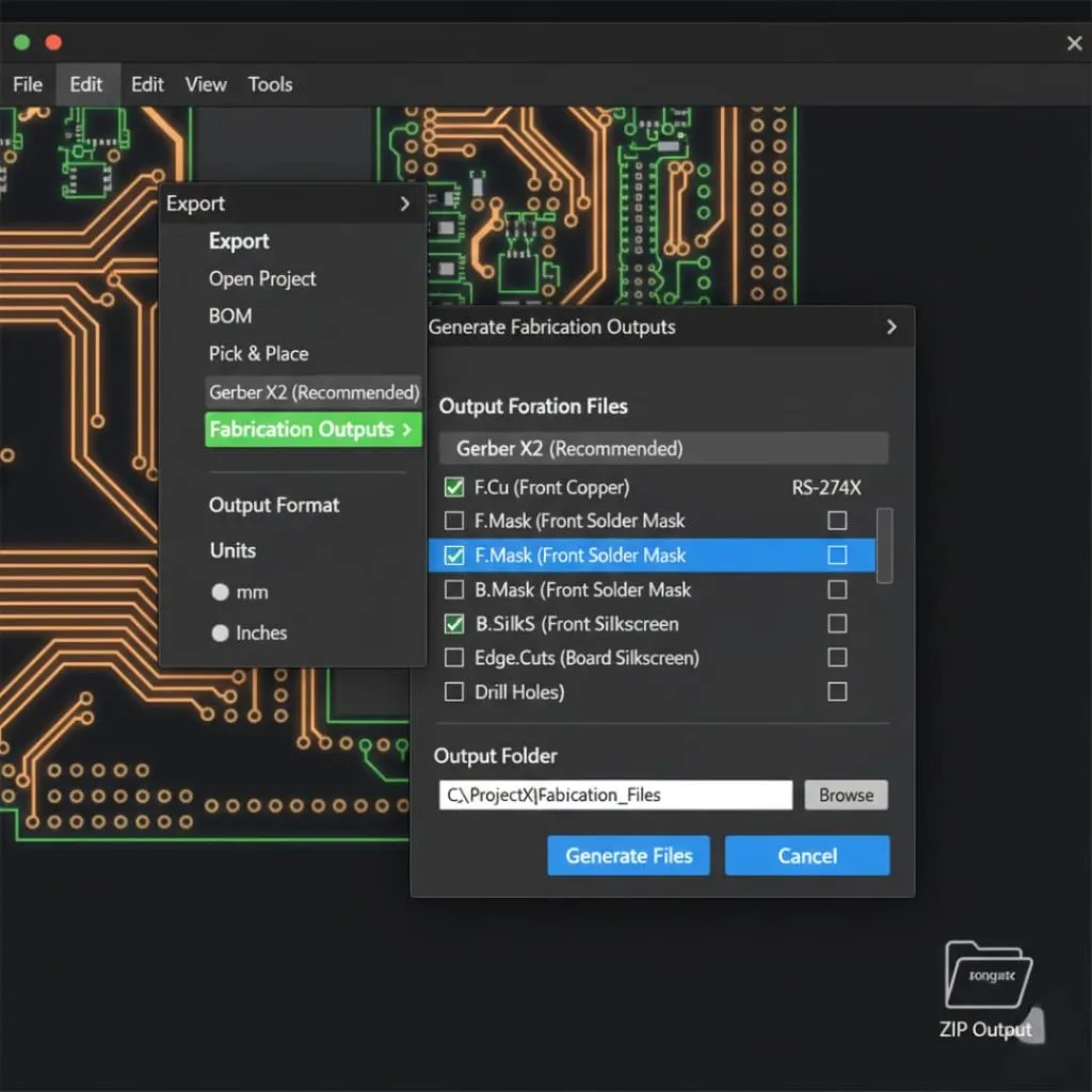
Simbeor is a trusted simulation tool. It calculates impedance by looking at track size, materials, and routing. This method works well for high-frequency circuits. Simulation tools also find problems like mismatched impedance before building the PCB.
Tip: Start using simulation tools early to save time and money.
Simulations match real-world results closely. For example:
4 ground vias have impedance between 30 and 75 ohms.
2 ground vias show steeper slopes, meaning more inductive behavior.
These examples show how accurate simulation tools are for measuring impedance.
Online Impedance Calculators
Online calculators are fast and easy for finding impedance. You just enter trace width, thickness, and dielectric constant. They are good for quick checks or early designs.
Different methods have varying accuracy. For example:
Method | Accuracy Level | Error Rate |
|---|---|---|
Wheeler’s equations | Very accurate | Less than 0.7% error |
IPC-2141 equation | Less accurate | Higher error rate |
Online calculators are not as precise as simulation tools. But they are helpful for quick estimates. They also show how design choices affect impedance.
Note: Always double-check online calculator results with other methods.
Practical Methods and Formulas
Practical methods use hands-on formulas to find impedance. These are helpful for checking simulation results or doing manual calculations.
Common formulas include:
Parameter | Formula/Description |
|---|---|
Odd-mode Impedance | Uses twin-rod transmission line formulas for inductance and capacitance. |
Effective Dielectric Constant | Relates to material properties like Dkxy and Dkz. |
Differential Impedance | Ztwin is twice Zodd. |
Impedance Standard Substrates are important for practical methods. They give stable reference points for measurements. These substrates reduce errors and work well for high-frequency circuits.
Using both practical methods and tools improves impedance control. This keeps signals strong and reduces mistakes, making circuits work better.
Factors That Change Impedance in PCB Design
Many things affect impedance in PCB design. Knowing these helps you control impedance and keep signals clear. Let’s look at three key factors: trace size, material properties, and distance to the reference plane.
Trace Size
The size of a PCB trace changes its impedance. Wider traces lower impedance, while narrower ones raise it. Thicker traces also lower impedance because they carry more current. To control impedance, you must calculate trace size carefully.
For example, if you need 50-ohm impedance, trace width must match the material and distance to the reference plane. A small change in width can cause big impedance differences. In one case, a trace meant for 50 ohms was designed at 0.35mm wide but ended up 0.3mm wide. This caused the impedance to rise to 53 ohms. This shows why accurate trace size is important.
Tip: Use online tools or simulators to find the best trace size for your design.
Material Properties
The dielectric constant (Dk) of PCB materials affects impedance. Dk shows how much energy a material can store compared to air. All PCB materials have a Dk higher than 1, and it changes with frequency. The mix of glass and resin in the material also changes the Dk, which impacts your PCB’s performance.
Materials with high Dk store more charge, which helps keep signals clear at high speeds. But they can also increase energy loss and signal interference. For example, materials with high Dk between power and ground layers improve capacitance. This lowers power network impedance and stabilizes input power. Balancing these factors is key for controlled impedance.
Note: Always check the dielectric constant when picking materials for high-speed designs. It affects signal flow and energy loss.
Distance to Reference Plane
How far a trace is from its reference plane changes impedance. Closer traces lower impedance, while farther ones raise it. This is important in multilayer PCBs, where the stackup sets the trace-to-plane spacing.
Tests show this effect clearly:
Distance Effect on Impedance | What Happens |
|---|---|
Trace closer to reference plane | Impedance goes down |
Trace farther from reference plane | Impedance goes up |
For example, if you need 50-ohm impedance, adjusting the trace-to-plane distance can help. But make sure these changes don’t hurt signal quality or manufacturability.
Tip: Use simulators to test how trace-to-plane distance affects impedance before finalizing your PCB design.
Parasitic Elements and Via Impedance
Parasitic elements and via impedance affect how well your PCB works. These unwanted electrical properties can mess up signals, lower efficiency, and add noise. Knowing their effects helps you design better circuits with controlled impedance.
What Are Parasitic Elements?
Parasitic elements are extra capacitance, inductance, or resistance in PCBs. They happen because of the board’s structure and materials. While you can’t avoid them, smart design can reduce their impact.
Parasitic capacitance slows signal rise and fall times. It lowers bandwidth and causes signal echoes or ringing.
Parasitic inductance raises impedance and voltage drop. It also adds switching noise, especially in fast circuits.
These effects distort signals, cause timing errors, and corrupt data. They also increase noise, lowering signal clarity.
Tip: Keep traces short and avoid sharp turns to reduce parasitics. Use good grounding to cut interference.
How Vias Affect Impedance
Vias connect PCB layers but bring parasitic capacitance and inductance. These can harm signal flow. The plated holes in vias create unwanted coupling between signal and ground layers. This can distort signals and hurt circuit performance.
Vias may cause crosstalk, where one signal interferes with another.
They waste power, making your design less stable and efficient.
At high frequencies, via impedance gets worse, adding noise and lowering signal quality.
To control via impedance, design vias carefully. Use back-drilling to remove unused parts of the via barrel. This lowers parasitic inductance and improves impedance control.
Designing for Controlled Impedance
To control impedance, consider parasitic elements and vias during design. Simulation tools can predict their effects on your circuit. Adjust trace width, spacing, and via placement to reduce problems and keep signals clear.
Note: Test your PCB in real conditions to ensure parasitics and via impedance don’t hurt performance.
By managing parasitic elements and via impedance, you can build PCBs that work well, even in fast or high-frequency designs.
Why Impedance Matching Matters
Impedance matching is key for making your PCB work well. It keeps signals clear, saves energy, and stops unwanted reflections. Without it, signals can get distorted, causing poor performance or failure.
Stopping Signal Reflection and Distortion
If impedance doesn’t match, signals bounce back on the line. These bounces mix with the original signal, causing distortion. This problem is worse in fast circuits, where small mismatches can ruin performance.
Impedance matching is crucial for high-speed PCB designs. It keeps signals clear and reduces reflections. Mismatched impedance can cause signal issues, EMI, and lower system reliability. Matching impedance improves signal quality and boosts PCB performance.
To avoid these issues, design PCB traces carefully. Use tools to calculate the right impedance. Controlled impedance helps signals move smoothly without distortion.
What is Reflection Coefficient?
The reflection coefficient shows how much signal bounces back from mismatched impedance. Use this formula to find it:
Reflection Coefficient (Γ) = (ZL - Z0) / (ZL + Z0)
Here, ZL is the load impedance, and Z0 is the line’s impedance. A zero reflection coefficient means perfect matching. Higher values mean more signal bouncing.
Changes in trace width can cause mismatched impedance and reflections.
Careful design and matching techniques reduce these problems.
Simulation tools help calculate reflections and fix mismatches.
By checking the reflection coefficient, you can spot and fix design issues.
How It Affects Signal and Circuit Performance
Impedance matching improves signal quality in your PCB. It ensures faster, stable operation, especially in high-frequency uses like HDMI or RF. Uneven impedance along traces causes reflections, hurting signal clarity and data flow.
Keeping impedance steady across traces protects data and signal quality.
Proper matching saves energy and makes circuits work better.
Learning impedance matching helps you build reliable PCBs, even for tough tasks.
Challenges and Solutions in Maintaining Controlled Impedance
Where Impedance Changes Happen
Impedance changes often happen in certain parts of a PCB. These changes can mess up signals and lower performance. Finding these spots early helps keep impedance steady in your design.
Many things cause these changes. Material properties, like the dielectric constant (Dk) and dissipation factor (Df), are big factors. Uneven Dk values change line impedance, while high Df values cause more signal loss. Trace size, like width and thickness, also affects impedance. Wider traces lower resistance, but uneven sizes can create mismatches.
The table below shows what affects impedance changes:
Material Property | How It Affects Impedance |
|---|---|
Dielectric Constant (Dk) | Changes line impedance; steady values reduce changes. |
Dissipation Factor (Df) | Lower values mean less signal loss and heat. |
Coefficient of Thermal Expansion (CTE) | Changes can stress multi-material PCBs. |
Conductor Surface Roughness | Rough surfaces increase signal loss. |
Trace Dimensions | Wider traces lower resistance and signal loss. |
Knowing these factors helps you design better PCBs. Use simulation tools and pick the right materials to fix these problems.
Working with PCB Makers
Teamwork with your PCB maker helps control impedance better. Makers have tools and skills to improve your design for steady impedance. Share your needs, like trace size and stackup info, early on.
PCB makers can suggest materials with steady Dk and low Df values. These materials keep signals clear and reduce impedance changes. They may also recommend methods like back-drilling vias to cut parasitic effects.
Tip: Talk often with your PCB maker to spot problems early. This saves time and ensures your PCB works well.
Following Design Rules
Using design rules is key to keeping impedance steady. Rules like IPC-2141 guide trace size, spacing, and material choices. These rules help you get steady impedance across your PCB.
Design rules also make sure your PCB works for fast systems. For example, following HDMI or USB rules ensures good signal flow. Use simulation tools to check if your design meets these rules before making it.
Note: Keep up with new rules to design PCBs that work for modern needs.
By fixing impedance changes, working with PCB makers, and following rules, you can build PCBs that work well and last long.
Figuring out impedance is important for making PCBs work well. Tools like simulators, online calculators, and formulas help get accurate results. You need to think about trace size, materials, and parasitic effects to keep signals clear. Working with PCB makers and following design rules also helps control impedance better.
The table below shows how good impedance practices improve PCB designs:
Practice | Benefit |
|---|---|
Smart Routing | Cuts down signal problems and keeps circuits reliable. |
Ground and Power Layers | Helps signals stay strong and gives a steady return path. |
Controls impedance and stops signal mixing, boosting reliability. |
By using these methods, you can create PCBs that work well and meet today’s needs.
FAQ
What does controlled impedance mean in PCB design?
Controlled impedance keeps signals steady by maintaining a set impedance. It stops signal problems like distortion and reflection, especially in fast circuits. To achieve this, adjust trace width, spacing, and material properties carefully.
How do simulation tools help calculate impedance?
Simulation tools check impedance by studying trace size, materials, and layout. They find mismatches and signal problems before production. Tools like Simbeor give precise results for fast designs, saving time and avoiding mistakes.
Why does trace width matter for impedance?
Trace width changes how signals travel. Wider traces lower impedance, while narrower ones raise it. Calculating the right width keeps signals clear and avoids mismatched impedance.
Can parasitic elements be fully removed?
Parasitic elements can’t be completely removed, but their effects can be reduced. Shorter traces, smoother layouts, and good grounding lower parasitic capacitance and inductance, improving signal quality.
What does the dielectric constant do in impedance?
The dielectric constant (Dk) shows how well a material stores energy. Higher Dk lowers impedance, while lower Dk raises it. Picking materials with stable Dk keeps signals steady in fast circuits.