Precision measurement captures accurate, high-fidelity data on physical process parameters. These parameters include flow, pressure, temperature, gas, and dimensions. Data transmission moves that data across systems reliably and quickly. Together, they enable real-time monitoring, control, and optimization in modern industrial environments. Accurate readings alone cannot improve a process. The data must reach the right system at the right moment. Measurement and transmission also support motion tracking, where acceleration data reveals how equipment behaves. Each capability has distinct strengths and limits. Their combination creates value that neither delivers alone. Understanding both is essential for engineers who specify, operate, and maintain industrial systems.
Key Takeaways
Precision means repeated measurements agree closely. Accuracy means a measurement is close to the true value. A tool can be precise but still inaccurate without proper calibration.
Data transmission moves sensor readings to controllers quickly and reliably. Fast, deterministic networks like Time-Sensitive Networking enable real-time monitoring and control.
Combining precise measurement with reliable transmission improves quality, reduces downtime, and supports predictive maintenance. Clean signals and fast delivery let teams act before problems grow.
Inertial measurement units (IMUs) track motion without external references. MEMS sensors offer low power, small size, and high shock resistance. Proper calibration is essential for trustworthy data.
Modernization faces challenges like signal interference, latency, legacy equipment, and cybersecurity risks. Retrofitting with IoT sensors and gateways helps bridge old and new systems.
Precision Measurement Basics

Precision Versus Accuracy
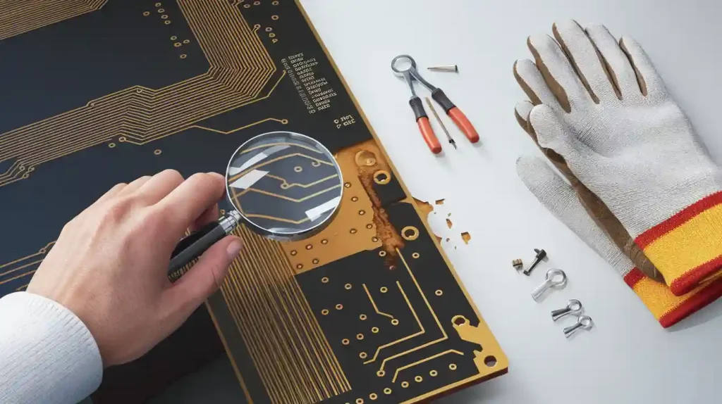
Precision measurement determines a physical quantity such as length, diameter, flatness, angle, or surface finish. It answers a specific question about a part or process. The result is a number that engineers can compare against a specification.
People often confuse precision with accuracy. The two terms describe different things. ISO 5725-1 defines accuracy as how close a measurement is to the true value. When applied to a set of measurements, accuracy combines a random-error component and a systematic-error component. Trueness is the closeness of the mean of the results to the true value, which reflects the systematic error. Precision is the closeness of agreement among the results themselves, which reflects the random error.
Per ISO 5725-1, “accuracy” describes how close a measurement is to the true value; when applied to a set of measurements, it combines a random-error component and a systematic-error component. Within this, trueness is the closeness of the mean of the results to the true value (the systematic error), while precision is the closeness of agreement among the results themselves (the random error).
Aspect
Accuracy
Precision
Meaning
How near a measured result is to the true/accepted value
How closely repeated measurements agree with one another
What it measures
Correctness of the result
Consistency/repeatability of the process
Role of true value
Central — compared against a reference or true value
Irrelevant — only mutual agreement of results matters
Error influence
Affected by both systematic (bias) and random errors
Mainly affected by random error (spread)
Quantification
Percent error relative to a known/reference value
Standard deviation, variance, or relative standard deviation
Dartboard analogy
Darts land near the bullseye
Darts cluster tightly together, wherever they land
Key takeaway
High precision does not guarantee high accuracy if a systematic bias exists
High accuracy is possible without tight clustering
A tool can deliver high measurement precision and still produce wrong results. A systematic bias, such as a miscalibrated instrument, shifts every reading in the same direction. Regular calibration against a known reference protects against this failure mode.
Why It Drives Industrial Performance
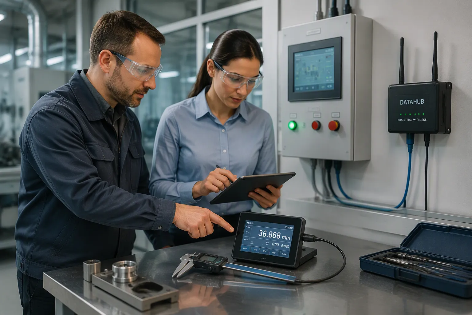
Common metrology tools turn these principles into practice. A vernier caliper measures the distance between two opposite sides of an object using a fixed arm and a movable arm with a vernier scale. A micrometer measures thickness or diameter with a calibrated screw turned by a thimble. A dial indicator shows small displacements and deflections during inspection. Surface plates, gauge blocks, and height gauges provide reference planes and known lengths for calibration. Each tool supports dimensional accuracy in its own way.
Precision measurement also supports safe operation, regulatory compliance, and long-term reliability. Out-of-calibration systems cause scrapping or reworking parts machined to wrong dimensions, lost shipments at customer inspections, costly warranty returns, and halted production for emergency recalibration. Top-performing plants lose as little as 0.6% of revenue to scrap and rework, while bottom performers lose up to 2.2%. Measurement errors drive this cost through false rejects and false accepts. Proactive verification and scheduled calibration catch errors before stoppages. Calibration records prove machines meet spec and support planned maintenance windows.
Motion and acceleration data extend this picture. Accelerometers mounted on spindles and frames capture vibration and acceleration profiles that reveal bearing wear or imbalance. Engineers who track motion at the machine level catch degradation early, before it shows up as a dimensional error in finished parts.
Data Transmission In Industrial Systems
From Sensor Signals To System Insights
Industrial data acquisition systems collect and transmit data without human intervention. The pipeline follows a fixed sequence. A sensor converts a physical quantity, such as temperature, strain, vibration, or pressure, into an electrical signal. Conditioning stages then amplify, filter, isolate, and linearize that tiny signal. An analog-to-digital converter samples the signal at a fixed rate and turns each sample into a number. The data then moves to a computer or controller over USB, PCIe/PXI, Ethernet, or a wireless link. Software finally displays, logs, and analyzes the results, and closed-loop systems use them to drive outputs.
Edge devices sit near machines and process data locally or act as first-in, first-out buffers. This design prevents network overload and data loss. These devices ingest readings from sensors, PLCs, and cameras through protocols such as OPC UA, IO-Link, and GenICam, then convert them into standard formats like JSON or CSV. Shared clocks, IEEE 1588 PTP, IRIG-B, or GPS timing keep channels aligned across locations. Effective handling of real-time data streamlines processes and raises production speed.
Reliability And Speed Requirements
Fine-grain monitoring pushes more data across the factory, so networks need lower latency and higher bandwidth. Interconnects form the final separable interface exposed to electrical noise and physical stress. Signal integrity therefore becomes harder to hold as data rates rise.
Technology | Supported Speed | Reliability Feature |
|---|---|---|
Industrial RJ45 jacks | Up to 10 Gb/s over 100 m | 360° shielding, shock and vibration resistance |
RJ45 cable assemblies | 100 Mb/s to 10 Gb/s | Industrial-graded for harsh environments |
Single Pair Ethernet, 20 MHz | 10 Mb/s | Single-pair transmission |
Single Pair Ethernet, 600 MHz | Up to 1 Gb/s over a single pair | Single-pair transmission |
Real-time high-speed connectors | High-frequency transfer | 100Ω differential / 50Ω single-ended impedance, EMC protection |
Wireless collection carries measurement data and control signals safely where cabling is impractical. Accelerometers on rotating equipment feed acceleration profiles into these links, and the resulting real-time data reveals wear before it becomes a fault. Teams that track motion this way catch imbalance early. Reliable transmission of real-time data also supports motion studies on robotic axes, where acceleration spikes signal collision risk. Dependable delivery of real-time data keeps every decision grounded in current conditions.
Combined Value Of Measurement And Transmission
Quality, Uptime, And Predictive Maintenance
Accurate measurement plus reliable transmission improves quality, repeatability, and reduced downtime. A remote monitoring study shows the pattern clearly. The system paired rigorous sensor upkeep with resilient transmission. Upkeep included antifouling coatings, automatic wipers, corrosion-resistant housings, and recalibration every two months. Transmission relied on GSM redundancy and IoT-based streaming.
Measurement practice | Transmission practice | Quality outcome | Uptime outcome |
|---|---|---|---|
Calibration protocols, antifouling coatings, wipers, bi-monthly recalibration | Resilient transmission strategies | Signal drift ≤ 3% over 4 years; sensor data loss < 5% | Stable operation at 24–32°C and >85% humidity for 4 years |
Sensors below the turbulence zone | GSM redundancy | Data continuity maintained | >95% communication uptime during monsoons; >90% data continuity |
ISO-calibrated validation, routine recalibration | IoT streaming with AI predictive analytics | Correlation coefficients above 0.92 | Reliability >90%; response time cut about 35% |
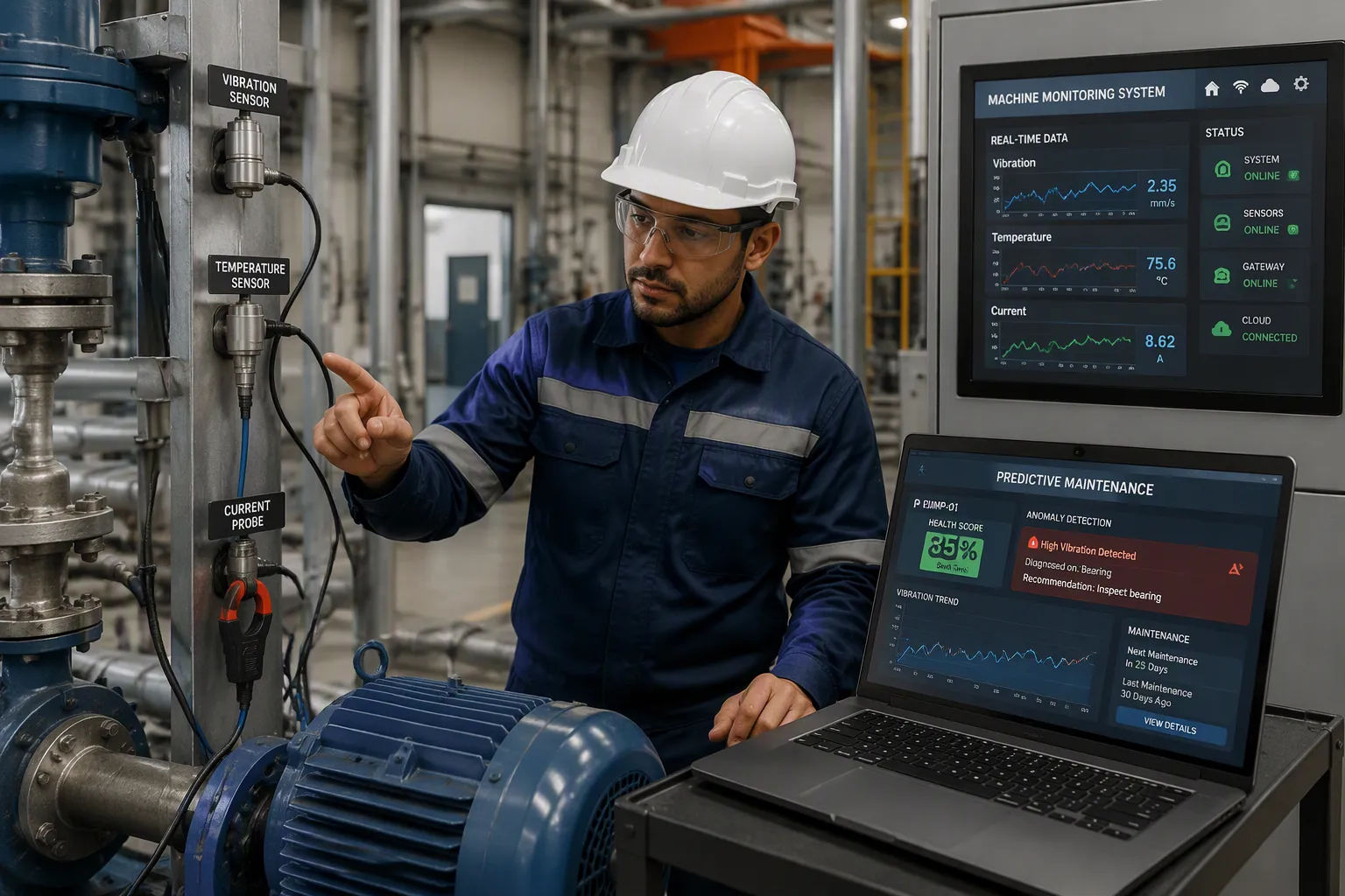
Predictive maintenance depends on the same pairing. Vibration, acoustic, temperature, magnetic flux, RPM, humidity, and current sensors each target specific fault modes. Multi-parameter devices combine them, which raises diagnostic confidence and reduces false positives. The analytics behind these tools need clean signals. Motor current signature analysis demands current accuracy better than 0.1% with minimal harmonic distortion. High-frequency vibration work needs stable group delay from DC to 10 kHz. Control panels must preserve signal integrity through EMI mitigation, proper grounding, and thermal stability. Real-time data then flows into the maintenance system, which creates work orders automatically. Teams review MTBF, MTTR, and alert precision, then retrain models to cut false alarms. One transmission operator unified siloed asset data into a knowledge graph and lowered downtime through predictive maintenance. A utility that rebuilt its IT operating model cut downtime by 80% and saved $20M, though that project centered on the operating model rather than measurement hardware.
Real-Time Decisions And Closed-Loop Control
Closed-loop control shows the combined value in its purest form. The loop continuously measures, compares, and adjusts through negative feedback. Encoders, resolvers, and load cells report position, speed, and torque. A controller compares each reading against the setpoint and sends corrective signals to hydraulic, pneumatic, or electric actuators. This cycle depends on fast, deterministic links. EtherCAT, PROFINET, and Ethernet/IP move real-time data among sensors, drives, and controllers. Low latency lets the controller act before a deviation grows. Deterministic synchronization coordinates multi-axis motion. Seamless sharing feeds MES and SCADA layers for monitoring and diagnostics.
Motion sensing adds another layer. Accelerometers on rotating equipment capture acceleration profiles that reveal bearing wear or imbalance. Real-time data from these devices supports near-real-time data review on the floor. Edge devices handle real-time data processing close to the machine, which protects bandwidth. Real-time analytics flag acceleration spikes on robotic axes before a collision occurs. A second round of real-time analytics compares trends across shifts. Every decision then rests on current conditions, not stale logs. Precision measurement supplies the truth, and transmission delivers it in time to act.
Key Technologies And Best Practices
Inertial Measurement Unit And MEMS Inertial Sensors
An inertial measurement unit tracks motion without any external reference. It combines accelerometers and gyroscopes to report acceleration, rotation and velocity. A mems accelerometer detects linear acceleration, and mems gyroscopes measure angular rate. Together they supply the raw imu sensor information behind every navigation and stabilization task. The technology behind imu sensors rests on silicon micro-machining, which keeps size, weight, power, and cost low. A Motus MEMS IMU weighs about 26 g, occupies roughly 16 cm³, and draws 1.4 W while holding high accuracy.
MEMS inertial sensors bring clear industrial benefits:
Low power draw suits battery-operated devices.
Fast gyroscopic initialization allows earlier use after startup.
High shock survivability supports robust operation.
Some mems gyroscopes now match certain fiber-optic gyroscopes.
An attitude and heading reference system builds on the same parts. It fuses sensor data into orientation/heading data for platforms that need stable attitude. Motion sensing at this level depends on tight inertial measurement unit specifications. Key figures include bias instability, which sets long-term drift, and scale-factor error. A drifting bias instability figure quietly corrupts orientation over time. High-accuracy rotational measurement therefore demands careful part selection. MEMS IMU technology also embeds local processing, so motion sensors can run machine-learning algorithms at low microamp consumption.
IMU Sensors, IMU Calibration, And Data Integrity
IMU sensors only deliver trustworthy real-time data after proper setup. IMU calibration establishes the reference point that every later reading depends on. Skip it, and the system loses that reference. A removed airbag control module or IMU, a replaced module, or a repositioned unit all trigger recalibration. Clearing codes without recalibration is a common and costly mistake.
Automated measurement systems strengthen this discipline. Automated robot calibration on the shop floor cuts commissioning time and holds consistency from the start. Continuous path monitoring catches backlash early and sustains repeatability. One on-site demonstration reduced a circular weld path from 90 arc points to 5 points in a single day. Such gains show how automation improves efficiency, repeatability, and accuracy at once. Reliable real-time data then flows into control loops, and inertial measurement becomes a dependable input rather than a source of drift.
Challenges And Considerations
Interference, Latency, And Legacy Integration
Industrial networks face several transmission obstacles. Traditional modules use half-duplex mode, which alternates transmission and reception over time. This design raises latency and reduces system efficiency, especially in real-time feedback scenarios. Dense factories share limited RF resources across many devices. Channel congestion then causes data loss and interference between devices. Traditional modules also handle few simultaneous device requests, which lowers transmission efficiency as IoT deployments grow. Signals degrade easily in high-interference environments, and packet loss can break automation and remote monitoring standards.
Challenge | Description | Impact |
|---|---|---|
Communication delay | Half-duplex modules alternate send and receive | Higher latency, weaker real-time feedback |
Channel congestion | Many devices share limited RF bands | Data loss and cross-device interference |
Limited concurrency | Modules handle few simultaneous requests | Lower efficiency in smart factories |
Signal disruption | Noise disrupts transmissions | Packet loss and missed accuracy targets |
Legacy equipment adds another layer. Older machines often lack built-in sensors, run proprietary software, and offer limited connectivity. Teams can retrofit rather than replace. They attach IoT sensors to capture vibration, temperature, energy, and flow. Gateways that support Modbus, OPC UA, and MQTT convert the data into modern formats. Edge processing cuts latency and bandwidth use before cloud storage and analytics. Remote Telemetry Units bridge contact closures and Modbus alongside newer protocols, and add-on expansion shelves let sites modernize gradually.
Cost, Security, And Workforce Readiness
Cost justification requires a life-cycle view. Sensor unit prices fall in a narrow band, so integration complexity drives total expense more than component price. Signal conditioning, calibration, firmware overhead, and long-term stability testing all add cost. Vendor services range from no support to full turnkey packages.
Sensor selection should not be guided solely by component price, but by the trade-off between electrical integration requirements, processing complexity, and long-term data reliability.
Cybersecurity demands equal attention. Strong authentication blocks unauthorized PLC access. IP whitelisting controls which devices communicate. Encrypted links protect data between robots, controllers, and monitoring equipment. Compliance with IEC 62443-4-2 covers control devices from design through deployment. Real-time network monitoring catches anomalies early. Workforce readiness matters too. Technicians need training on calibration, protocol bridging, and security hygiene. Accelerometers on rotating shafts feed acceleration profiles into these systems, and staff must read them correctly. Motion studies on robotic axes rely on clean acceleration signals. Poorly trained teams misread acceleration spikes and miss faults. Bias instability in inertial sensors compounds the problem when nobody checks drift.
Precision measurement and data transmission work best as a pair. Their combined value exceeds what either delivers alone. Together they raise efficiency, strengthen reliability, and give teams better information for decisions.
Edge computing will push real-time data processing closer to the machine. AI-powered edge devices will handle real-time analytics on site. Wireless sensing will carry measurements where cables cannot go. Accelerometers on rotating equipment will stream acceleration profiles, and edge models will read those signals for early fault signs. Each acceleration spike becomes a warning, and each motion trend informs maintenance planning. Readers should evaluate measurement and transmission together, not in isolation.
FAQ
How does precision differ from accuracy in practice?
Precision describes how closely repeated readings agree with one another. Accuracy describes how close a reading sits to the true value. A miscalibrated instrument can deliver tight clusters of wrong numbers. ISO 5725-1 separates the two through trueness and random error. Regular calibration against a known reference keeps both in check.
Why does data transmission matter as much as the sensor itself?
A perfect reading has no value until it reaches the controller in time. Time-Sensitive Networking carries data up to 1 Gbps with guaranteed low latency. Edge devices buffer and process readings near the machine. This design protects bandwidth and prevents data loss. Measurement supplies the truth, and transmission delivers it when decisions still matter.
Where do inertial sensors fit into an industrial measurement plan?
An inertial measurement unit pairs accelerometers with gyroscopes to track motion without an external reference. MEMS versions keep size, weight, power, and cost low. They capture acceleration profiles on spindles and robotic axes. Bias instability sets long-term drift, so part selection and calibration deserve careful attention.
What should teams check before trusting motion data?
Calibration comes first. A replaced, repositioned, or removed IMU needs recalibration before any reading counts. Teams should also verify synchronization across channels using shared clocks or IEEE 1588 PTP. Automated calibration cuts commissioning time and holds repeatability. Clean signals then feed control loops as dependable inputs.
Which obstacles slow modernization the most?
Legacy machines often lack sensors and run proprietary software. Retrofits with IoT sensors and protocol gateways bridge Modbus, OPC UA, and MQTT without full replacement. Cybersecurity needs equal weight, and IEC 62443-4-2 covers control devices from design through deployment. Workforce training on calibration and security hygiene rounds out the plan.