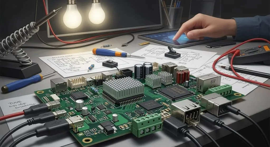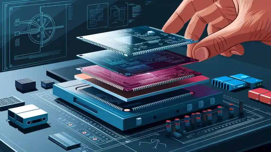
Designing and building a set-top box in 2026 means planning early, with a strong focus on hardware design from the very start. You must think about the circuit board, the case, the cables, the software, and the tests—all of which hinge on solid hardware design choices. This helps keep the product reliable and affordable. Are you finding it hard to launch your streaming device on time and within budget? This article explains the whole process, from the first sketch to the final product, emphasizing how hardware design sets the foundation for everything else. These two steps—design and assembly—work together like two sides of the same coin, but without a robust hardware design, the entire system can’t function as one unit. A reliable set-top box starts with smart hardware design that meets strict rules. All its parts must fit and work together smoothly, which is only possible when hardware design is prioritized early. Good hardware design saves money by avoiding costly fixes later.
Key Takeaways
Plan your hardware design early so you can avoid expensive fixes later.
Pick a processor that fits your budget and meets your performance needs.
Use Design for Manufacturing rules so parts fit together easily and stay cool.
Choose a manufacturing partner that tests well and keeps clear records.
Talk to your partner early in the design phase to avoid delays.
Set-Top Box Hardware Design Essentials
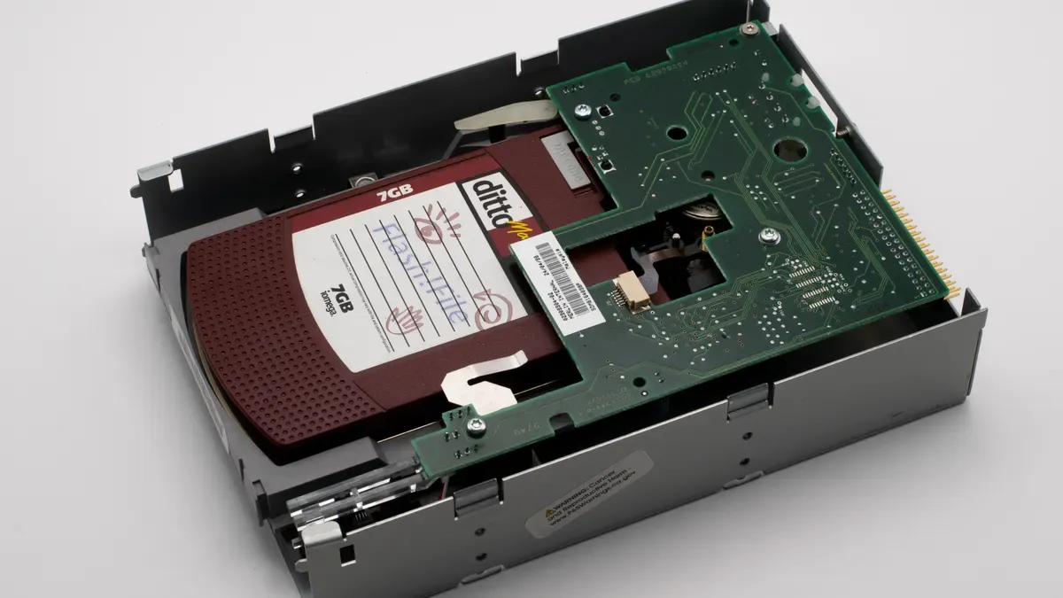
The hardware design of a set-top box starts with the processor. This System-on-Chip (SoC) acts as the brain of the device. It handles video decoding, graphics rendering, and system operations. A good SoC supports 4K and 8K video resolution with High Dynamic Range (HDR) while keeping power low.
Core Platform and Processor Selection
The right SoC platform determines the system capability. Three platforms lead the set-top box market in 2026: the RK3528, the S905X5M, and the RK3576.
SoC Platform | Key Specifications | Strengths | Limitations |
|---|---|---|---|
RK3528 | Quad-core Cortex-A53/A55, integrated Wi-Fi 6, HDMI 2.1, sub-€50 price | Low power draw, stable Android 13–14 support, native AV1 decode | Mali-G31 GPU limits complex UI animations; no hardware VP9 Profile 2 decoding |
S905X5M | Quad-core Cortex-A53/A55, integrated Wi-Fi 6, HDMI 2.1, sub-€50 price | Better GPU (Mali-G31MP2), full 8K@60Hz output, HDMI 2.1 eARC support, Bluetooth 5.4 | Higher thermal output; some units throttle under sustained load |
RK3576 | Octa-core A55, 8GB RAM standard, PCIe 3.0 interface for NVMe expansion | High RAM capacity, expandable storage via NVMe | Few verified retail units in EU; firmware maturity lags behind RK3528 |
For reliable streaming with minimal maintenance, a set-top box based on the RK3528 works well. It costs between €42 and €49. The system includes 4GB RAM and eMMC 5.1 storage. The S905X5M suits 8K TV owners. It costs between €58 and €67. The RK3576 offers high RAM capacity for demanding applications. The set-top box design for the S905X5M must account for higher heat output.
For raw 8K decoding, the Amlogic S928X-J stands apart. It supports native 8K decode and high-bitrate IPTV stability.
The Amlogic S928X-J is currently the most capable for raw 8K decode and AV1 throughput. It is the only current option with verified capability for native 8K decode, high-bitrate IPTV stability, or use as a media hub for 5+ years.
The Rockchip RK3588 also supports 8K at 60fps with native AV1 support. The Allwinner H728 only reaches 4K at 60fps with basic AV1 support. These differences guide the choices for each set-top product. A set-top box design for 8K requires more robust cooling. Each set-top platform needs its own thermal solution.
Connectivity, OS, and Security Requirements
A device must connect to home networks and other devices. The connectivity choices impact the assembly process. Wi-Fi 6E and Wi-Fi 7 offer faster speeds for streaming. Bluetooth 5.4 enables wireless peripheral connections. Ethernet provides a stable wired connection.
The operating system defines the user experience. Android TV dominates the interactive streaming platform market. Linux offers more control for custom applications. The OS choice affects firmware loading during assembly. Android TV requires more storage and complex flashing procedures. Linux uses simpler update mechanisms. A set-top with Android TV needs more careful firmware planning.
Network connectivity options influence antenna placement in the enclosure. Wi-Fi antennas need careful positioning to avoid interference. The pcba design must account for antenna traces and RF shielding.
Security requirements add another layer. The system must support secure boot and encrypted storage. These features protect against unauthorized access. A secure set-top must include hardware security modules for DRM compliance.
The product must balance these factors with cost. A well-planned approach considers connectivity, OS, and security from the start. This prevents costly redesigns.
Box Build Assembly Process and Components
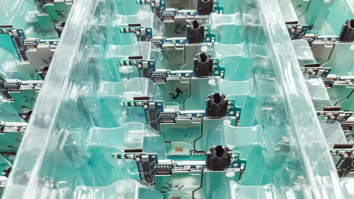
Box build assembly turns a bare circuit board into a finished product ready for store shelves. This full process covers every step from the pcba leaving the soldering line to the final set-top box in its retail package. A skilled manufacturing partner handles the whole workflow, from gathering parts to final packaging.
From PCBA to Finished Product: A Step-by-Step Flow
The box build assembly process follows a strict order. Each stage builds on the one before it. Skipping any step creates defects that show up later in the field.
Kitting and Material Procurement: The manufacturer gathers all needed parts, including the pcba, cables, enclosures, and fasteners. Proper kitting prevents delays and ensures each set-top gets the right components.
PCB Inspection: Technicians check the printed circuit board assembly for flaws. Automated Optical Inspection (AOI) finds surface issues like solder bridges, missing parts, or polarity problems. X-ray inspection checks hidden solder joints on ball grid array packages.
Sub-Assembly Integration: Power supplies and cooling fans get tested separately before final assembly. This step catches bad sub-assemblies early, saving both time and money.
Mechanical Assembly and Final Product Integration: Workers mount the pcba with proper airflow spacing, apply thermal interface material, route cables safely, and fit everything into the enclosure. This stage needs precision and careful attention.
Wiring and Connectivity: Technicians double-check all connections to prevent electrical problems. Cable harnesses must route cleanly without pinching or stress points.
Testing and Quality Control: The full system goes through functional testing, including power-on checks, interface validation, and signal verification. Burn-in testing stresses the unit to reveal early failures. Safety and compliance testing verifies electrical safety standards.
Final Inspection and Documentation: Workers verify workmanship, labeling, and test status before shipping. Complete records support troubleshooting and future improvements.
This step-by-step approach ensures every set-top box meets documented requirements. The final functional test checks the whole system, not just individual boards.
Enclosures, Cable Harnesses, and Power Supplies
The enclosure protects sensitive circuit boards and wiring from physical damage and electromagnetic interference. Material choice directly affects thermal management and RF shielding. Plastic enclosures cost less and offer design flexibility but provide limited heat dissipation. Metal enclosures conduct heat well and block electromagnetic interference but add weight and cost. Many set-top designs use plastic with internal metal shields for critical parts.
Thermal design needs careful planning. The enclosure must allow passive cooling through vents and heat sinks. Thermal interface materials fill gaps between hot parts and heat spreaders. These materials must apply easily during assembly to keep production speed up.
Cable harnesses need deliberate planning during the design phase. Each wire must route cleanly without interfering with other parts. Proper strain relief prevents connector damage during handling. The harness layout must fit the final assembly steps without forcing technicians to bend wires sharply.
Power supplies convert wall current into the voltages the system needs. The power supply must match the set-top’s power needs while fitting within the enclosure’s physical limits. System integration ensures the power supply, pcba, and enclosure work together as one unit.
A well-planned box build assembly process produces fully integrated electronic systems that work reliably for years. The manufacturing partner must understand how each part interacts with the others. This understanding prevents costly rework and field failures.
Design for Manufacturing in Set-Top Boxes
Design for Manufacturing (DFM) connects a CAD model to what happens on the assembly line. A set-top box design that skips DFM rules causes delays, rework, and failures in the field. During hardware design, engineers must think about how workers will build, test, and fix each unit.
Connector Placement and Test Access
Connector placement affects how easily workers can test a set-top box during box build assembly. Every port needs clear space for test probes and cables. Engineers should put connectors on the same edge of the pcba when possible. This setup makes automated testing easier and cuts handling time.
The pcba design must also follow DFM rules for component layout. The table below shows key guidelines:
DFM Technique | Quantitative Guideline |
|---|---|
Component Clearance | Minimum 0.25mm between parts |
Trace Spacing | 0.2mm (6-8 mils) minimum |
Current Routing Width | 6-8 mils for 1A; 20-30 mils for 2-3A |
Turn Geometry | 45-degree turns (eliminates acid traps) |
Trace Length | Keep under 10 inches for signals up to 100 MHz |
Fiducials | Place three target marks for assembly tool accuracy |
These rules keep signals strong and stop crosstalk. Three fiducials on the board help machines place parts accurately. Short, direct traces lower noise and signal loss. Keeping parts spread out maintains 10-15 mils spacing to avoid heat buildup. Thermal vias under high-power chips pull heat away from hot spots. Copper pours around hot components spread heat and improve cooling.
Set-Top Enclosure and Thermal Design
Thermal management is a key DFM concern for any set-top system. Poor thermal design causes field failures and expensive rework. The enclosure must support passive cooling through conduction, radiation, and natural convection. Common solutions include:
Extruded Aluminum Heat Sinks: the most common type, found in routers, set-top boxes, and SSDs
Heat Pipes & Vapor Chambers: suitable for high-heat-density processors in compact fanless designs
Strategically Vented Enclosures: leverages natural convection (chimney effect) without moving parts
Phase Change Materials (PCMs): absorb thermal spikes by melting, ideal for intermittent high-performance loads
Large heat sinks with wide fin-to-fin spacing work well. Heat spreaders move heat across a bigger area. In tight spaces, heat pipes carry heat from the processor to a spot with more surface area for cooling.
Thermal interface materials (TIMs) fill gaps between hot parts and heat spreaders. Choosing and applying TIMs directly affects box build assembly success. Engineers should:
Select thermal pad thickness between 0.5 and 3.0 mm to match the mechanical gap
Apply pad compression of 10% to 30% to ensure consistent contact
Verify heat sink flatness before assembly
Check fan airflow direction and cable clearance
Place temperature sensors correctly
Verify thermal compound coverage to avoid voids
A 1.0 mm pad over a 1.5 mm gap fails; a 2.0 mm pad with 25% compression gives better stability. Use the thinnest practical layer of TIM to lower thermal resistance. Use high clamping force to get metal-to-metal contact and fill surface gaps. Mounting surfaces should be as parallel as possible. Follow manufacturer torqueing sequences to apply correct clamping load. Mechanical fasteners give steady force on graphitic or metallic TIMs.
The manufacturing partner must understand how each part interacts with the others. This understanding prevents costly rework and ensures the final set-top box meets all performance requirements.
Choosing a Box Build Manufacturing Partner
Picking the right partner for set-top box assembly takes careful thought. A manufacturer with proven turnkey experience handles everything from getting parts to final packaging. This cuts down on logistics headaches and gets your product to market faster. Look for partners that offer complete PCBA, cable, and enclosure assemblies all in one place.
Evaluating Experience and Turnkey Capabilities
Quality control is the first thing to check when looking at a potential partner. Buyers should confirm strong quality control steps, including checking parts when they arrive, audits during production, and final sample checks. Certifications matter too. IPC-A-610 certification confirms solder quality standards. ISO 9001 shows solid quality management systems. UL approvals verify product safety compliance.
A strong partner offers common box build assembly services that cover the whole production journey. These services include sub-level product assembly, system level assembly, component labeling, housing fabrication, software configuration, and packaging. In-house tooling for rapid enclosure prototyping speeds up design iterations. Clean-room assembly facilities protect sensitive electronics from contamination. Environmental testing labs perform IP ratings, EMI/RFI checks, and thermal cycling tests.
Supply chain resilience becomes critical in 2026’s volatile component market. Toyota’s experience after the 2011 earthquake shows the value of mixing just-in-time efficiency with strategic inventory buffers. A reliable partner diversifies sourcing strategies across multiple suppliers and geographic regions. They keep safety stock on true risk components rather than broadly increasing inventory. Early supply chain engagement during new product introduction helps spot constrained technologies before production ramps.
Testing Protocols and Documentation Standards
Rigorous testing protocols separate dependable manufacturers from unreliable ones. The final functional test verifies the complete system, not just individual boards. Burn-in testing stresses units to reveal early failures. Firmware validation confirms the software loads correctly and operates as intended. Product verification ensures each set-top meets performance specifications.
Documentation standards ensure repeatability across production runs. Detailed work instructions guide technicians through each final assembly operation. Traceability records track every component back to its source. Complete documentation includes bills of materials, wiring diagrams, CAD files, and test procedures. A good partner provides transparent reporting on quality metrics and test results.
The final test should include visual inspection, factory acceptance testing, and functional checks. Testing capabilities must cover both hardware and software aspects of the set-top. Clear service level agreements define response times for design reviews, purchase order acknowledgments, and progress reporting. These agreements protect both parties and set expectations from the start.
A partner that combines strong testing and verification with clear documentation delivers consistent, reliable set-top boxes. This approach prevents field failures and reduces costly rework. Companies should evaluate potential partners against these criteria before committing to production.
Successful set-top box hardware design and manufacturing in 2026 demand collaboration from the concept stage. Early engagement with a manufacturing partner prevents costly design flaws and supply chain delays. A reliable set-top requires careful planning across every stage, from processor selection to final assembly.
Engineers should evaluate their current set-top box design against the DFM principles discussed. They must initiate conversations with potential partners now, not later. The right partner brings turnkey capabilities that streamline the entire system. This approach ensures a cost-effective product launch.
With proper planning, teams achieve a dependable set-top box manufacturing outcome. The process rewards those who act early and think holistically about the complete system. A well-executed set-top box reaches the market with fewer defects and lower total cost.
FAQ
How does processor choice affect the final product cost?
The SoC platform sets the bill of materials. The RK3528 costs between €42 and €49. The S905X5M ranges from €58 to €67. Better performance needs better cooling, which raises enclosure and assembly costs. Pick your budget target early in the design phase.
What testing does a set-top box need before shipping?
Every unit needs functional testing, burn-in testing, and firmware validation. Automated Optical Inspection checks solder joints on the pcba. X-ray inspection verifies hidden connections on ball grid array packages. Final inspection confirms workmanship and labeling before packaging. These steps stop field failures and costly returns.
How does thermal design impact the enclosure choice?
Plastic enclosures offer design flexibility but limit heat dissipation. Metal enclosures conduct heat well and block electromagnetic interference. Engineers must plan vents, heat sinks, and thermal interface materials during hardware design. A 1.0 mm thermal pad over a 1.5 mm gap fails. A 2.0 mm pad with 25% compression provides stable contact.
What documentation should a manufacturing partner provide?
A reliable partner supplies detailed work instructions, traceability records, and test procedures. Complete documentation includes bills of materials, wiring diagrams, and CAD files. Clear service level agreements define response times for design reviews and progress reporting. These records ensure repeatability across production runs and support troubleshooting when issues arise.
When should engineers engage with a box build partner?
Early engagement prevents costly design flaws and supply chain delays. Engineers should evaluate their set-top design against DFM principles before finalizing the CAD model. Conversations with potential partners should begin during the concept stage, not after production starts. This approach streamlines the entire system and reduces total cost.