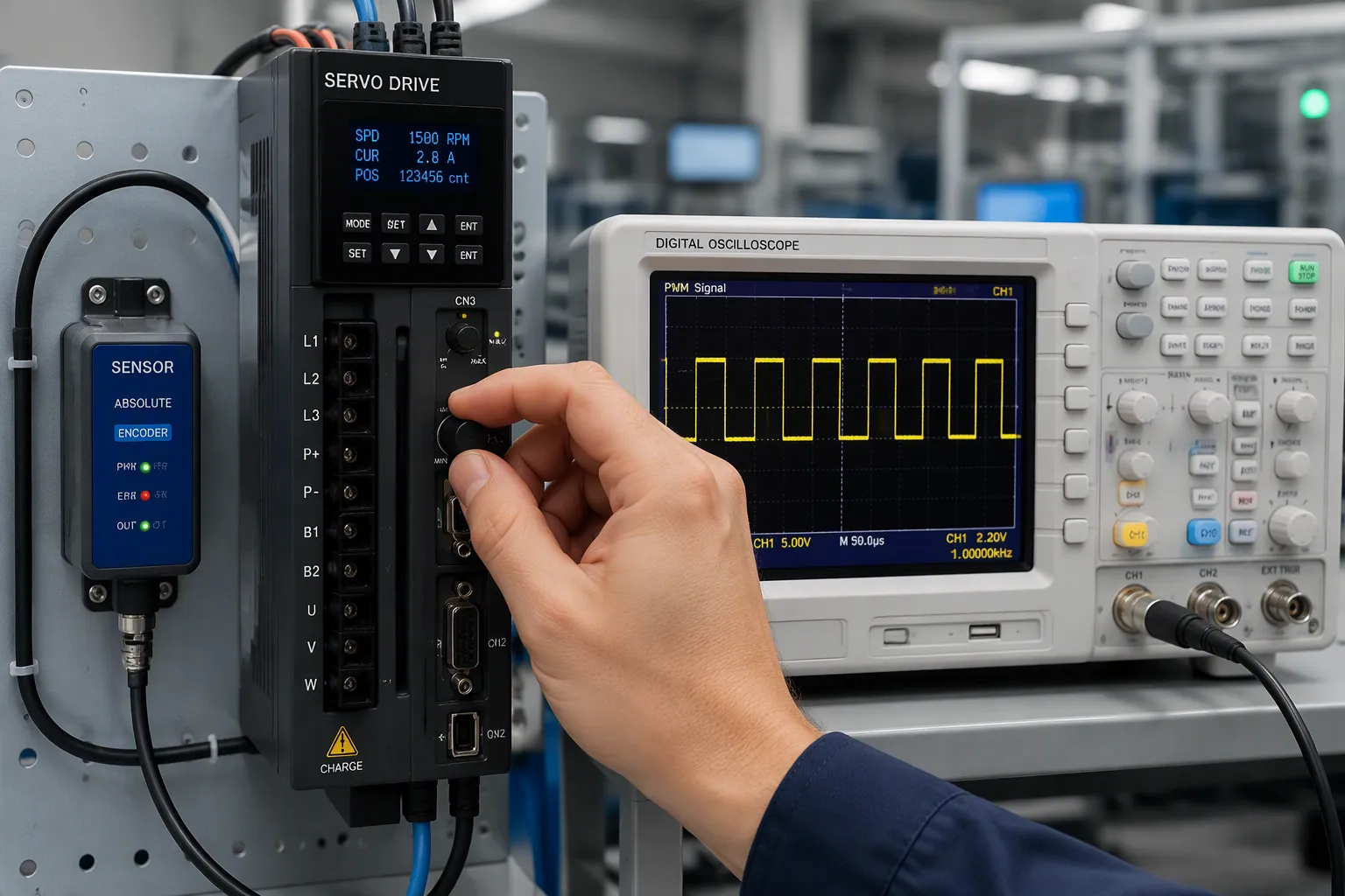
Servo drives use PWM to set a target position or speed. Sensors report the actual value in real time. The drive then fixes the gap in a closed loop. PWM, or pulse-width modulation, turns a signal on and off very fast. The duty cycle is the on-time fraction, and it sets the command level. Closed-loop control means the drive compares the command to feedback and adjusts its output until the error gets smaller.
Hardware engineers and electronics product teams need board-level facts, not slogans. Servo drives are at the heart of motion control, and small design choices decide whether a servo motor holds position or hunts. This discussion covers command encoding, feedback sensing, the combined loop, and power-stage trade-offs.
Key Takeaways
PWM duty cycle sets the command for servo drives, so clean timing ensures accurate motion.
Pick the right sensor for your precision needs: potentiometers for basic tasks, encoders for high accuracy.
Closed-loop control checks the command against the feedback to fix errors and keep motion steady.
A good power stage design with dead-time control and current sensing protects the drive and motor.
Use DFM guidelines from the start to prevent manufacturing problems and keep servo performance reliable.
Servo Drives and PWM Control
A servo drive is the power interface and execution stage of a motion system. It gets a command from the motion controller, turns that command into a switching pattern, and drives the motor windings. The drive does not decide where the load should go. It carries out the command and reports back through its feedback path.
Duty Cycle and Command Encoding
The duty cycle carries the command. A wider pulse tells the drive to move toward one end of travel; a narrower pulse moves it toward the other. In RC-style designs, a pulse near 1.5 ms usually means center, and the pulse width shifts above or below that value to set the desired position. Industrial servo drives often encode speed or torque the same way, with the duty cycle mapping to a commanded current or velocity.
The encoding scheme matters because servo motors respond to average voltage, not to individual edges. A clean duty cycle produces a predictable average. A distorted one produces a command the drive never intended.
PWM Timing and Refresh Accuracy
Timing jitter is the enemy of precise motion. Servo drives compare each incoming pulse against an internal time base. Jitter on that pulse shifts the decoded command, and the loop then chases a target that keeps moving. Refresh rate sets how often the command updates. Too slow a refresh leaves servo motors lagging behind fast-changing setpoints.
Board-level layout affects both. Route the PWM input away from switching nodes, keep the trace short, and give the timer a stable clock source. Servo drives that hold position well usually start with a clean, well-clocked command input.
Note: Verify refresh rate against the load’s dynamics, not against the datasheet maximum alone.
Sensor Detection and Feedback Hardware
The feedback path decides how well servo drives know the true position of the load. A sensor turns physical motion into an electrical signal. Servo drives then compare that signal against the command. Feedback quality sets a hard ceiling on achievable precision, no matter how fast the control loop runs.
Potentiometers, Encoders, and Hall Sensors
Each sensor type trades resolution against cost and board space. The table below summarizes typical specifications.
Sensor Type | Resolution | Accuracy |
|---|---|---|
Absolute encoder (FANUC) | 24-bit | ±2.5 μm positioning accuracy |
Absolute encoder (Mitutoyo) | 0.1 arcsecond rotary; nanometer-level linear | ±0.5 μm linear; ±1 arcsecond rotary |
General absolute encoder | Exceeds 16-bit | Strong noise immunity, discrete digital output |
Linear potentiometer (Hall effect, FANUC) | Analog | Linearity better than 0.1% full range |
General potentiometer | Analog | ±1–2 mm positioning range |
Potentiometers cost the least. Hall sensors fall in the middle on price. Optical encoders are top-tier parts, and their precise build only justifies the cost when the job truly needs it. General potentiometers work well for ±1–2 mm positioning. Work below a millimeter calls for optical encoders. Servo motors that use potentiometer feedback also need shielding and filtering, since analog noise spoils the voltage signal.
Noise Filtering on Feedback Lines
Noisy lines spoil master position data. Long cable runs, weak shielding, and nearby power wires all add error. Differential encoder signals block common-mode noise well. Keep feedback cables away from motor power wiring. Choose high-resolution encoders when the motion profile needs tight synchronization.
Modern smart encoders report internal temperature and signal-quality bits. A drop below 90% signal quality warns of coming failure from vibration or oil ingress. Watch for on-and-off soft position errors and erratic torque spikes. Servo drives that track encoder signal-to-noise ratio catch these faults early. Servo motors then keep their home reference instead of losing it mid-cycle.
Closed-Loop Control in the Servo Drive
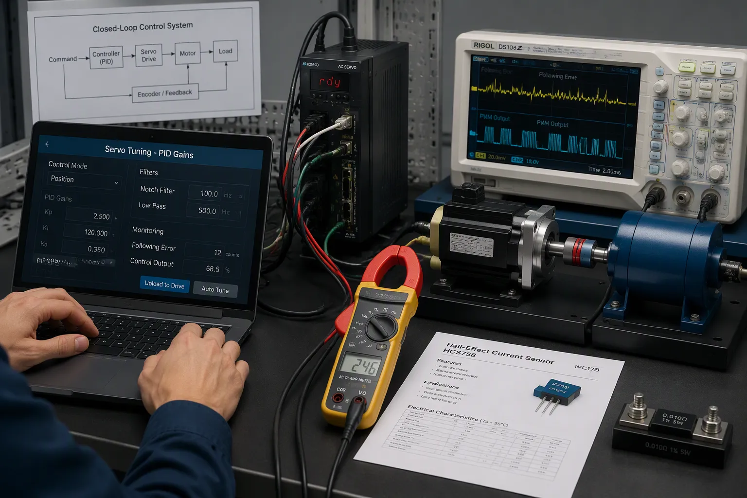
A command by itself does not make the motor move. A closed-loop control system checks the position you want against the position it measures. Then it acts on the difference. That difference is called the following error. Servo drives send it to a correction block, and the output drives the power stage. This is where PWM commands and sensor data finally come together.
Error Correction and Stabilization
Most servo drives use a PID controller to correct errors. The proportional term reacts to how big the current error is, and it works like system stiffness. The integral term adds up past errors to remove steady-state offset, and an integration limit keeps it from causing oscillation. The derivative term responds to how fast the error is changing, and it provides damping against overshoot.
Tuning follows a practical order. Engineers raise Kp until a slight overshoot shows up, increase Kd to reach critical damping, then set Ki as low as possible to clear leftover error. One published tuning example uses Kp = 1, Ki = 2, and Kd = 0.05. A common rule sets Ki between 1/10 and 1/2 of Kp, and smaller servo motors use larger ratios. When no Kd value stabilizes a given Kp, the guidance is to cut Kp by 35–50% and retune.
Basic PID cannot fix every error. Harmonic compensation corrects repeatable torque and feedback disturbances tied to motor pitch or one mechanical revolution. Error mapping stores laser interferometer data in non-volatile memory and applies interpolated corrections in real time. Dual-loop control adds a second encoder on the load, so the position loop sees the true load position. These methods extend a closed-loop feedback system beyond what gain tuning alone can do.
Current Sensing and Stall Detection
Current sensing protects the drive and closes the torque loop. Two methods dominate, and each one has trade-offs.
Attribute | Hall Effect Sensor | Shunt Resistor |
|---|---|---|
Isolation | Galvanic isolation | None |
Accuracy | Good in closed-loop versions | High precision and stability |
Cost | Higher | Low |
Power loss | Minimal insertion loss | I²R heat dissipation |
Best for | High-current, isolation-critical drives | Low-voltage, compact designs |
Where the shunt sits changes what the drive can detect. Low-side shunts sit near ground and cannot detect shorts to ground. High-side shunts leave the system ground clean but need sensing ICs rated for bus voltage. In-line shunts place one resistor per motor phase and give the most accurate result, independent of FET state.
Stall detection builds on this data. A stalled servo motor draws rising current while position stops changing. The drive compares current against a threshold and cuts output or folds back the command. Real-time feedback of current and position together separates a real stall from a brief load spike. That distinction protects the motor windings and the board without nuisance trips.
Power Stage and Precise Motion Design
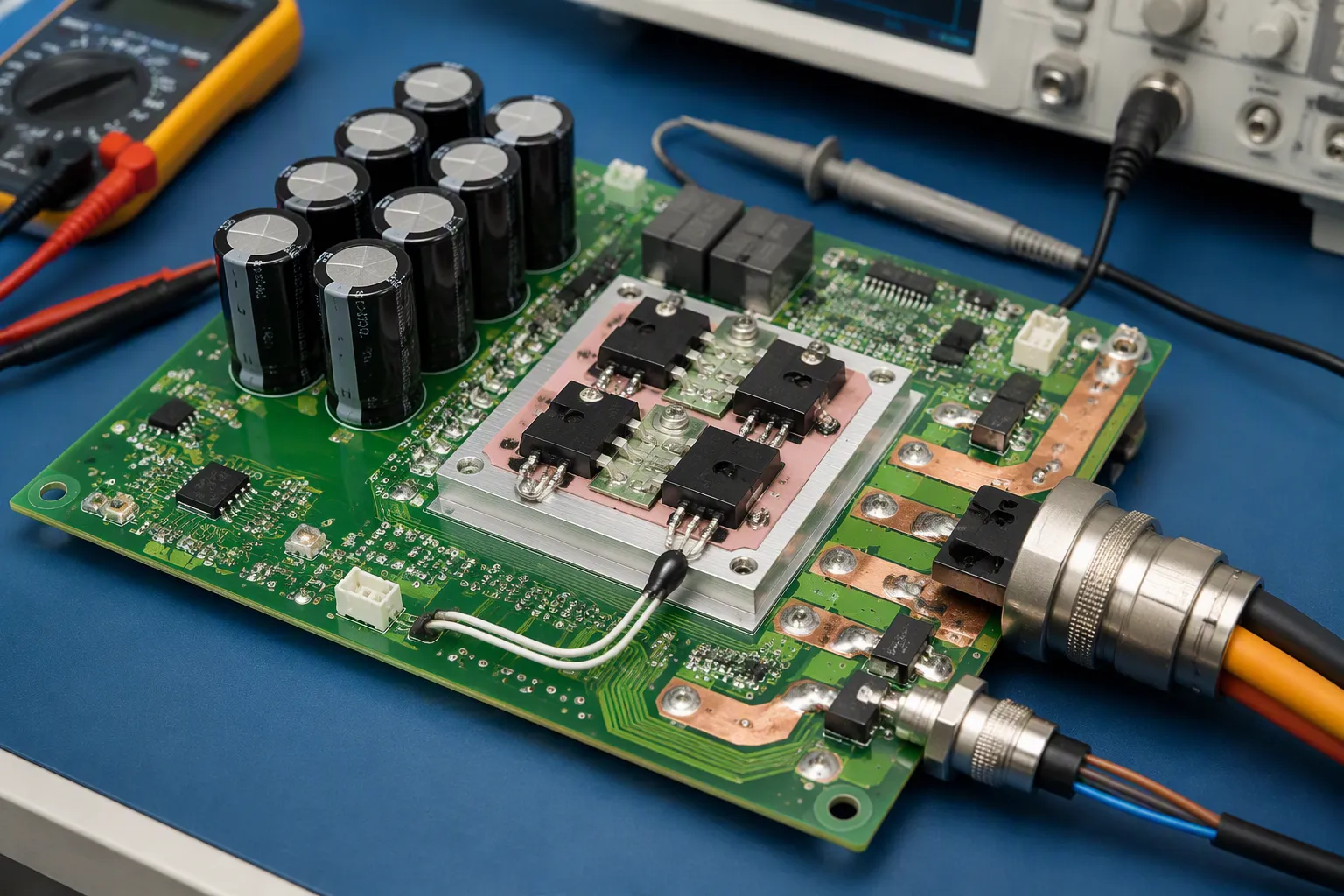
The power stage changes low-voltage commands into motor current. How it is laid out and which parts are chosen decide whether precise motion stays steady under load.
H-Bridge, Back-EMF, and Capacitance
A MOSFET H-bridge switches the bus voltage across the windings. Dead-time control stops shoot-through, which is when both devices in one leg conduct at the same time. Typical dead time for silicon MOSFETs runs 100–300 ns. A safe rule sets dead time above the maximum turn-off time plus margin, such as 200 ns for a 50 ns turn-off. Too much dead time drops effective voltage and raises ripple.
Recommendation | Dead-time value | Rationale |
|---|---|---|
Typical silicon MOSFETs | 100–300 ns | Full turn-off before the complement turns on |
Margin over turn-off | Turn-off time + margin | Covers worst-case delay |
Programmable driver (LM5106) | 100–600 ns | Resistor-adjustable |
Back-EMF rises with speed and fights the commanded voltage. Build a full voltage budget across supply tolerance, cable drop, load sag, and regenerative rise. Add 10–15% headroom at both ends. Sensorless designs estimate back-EMF with a sliding-mode observer, then work out rotor speed and position. That method gets worse at low speed and fails at standstill.
Size the DC-bus capacitor for peak ripple current and keep voltage ripple typically below 5%. Where regenerative braking returns energy, provide an absorption path such as braking resistors so the voltage rise does not overstress the power stage.
Thermal, Connector, and DFM Trade-Offs
Connectors and harnesses must carry the current without too much heating. Match the contact rating to the conductor.
Connector Type | Pins | Voltage / Current per Contact | IP (mated) |
|---|---|---|---|
M23 circular | 12 or 17 | 400V / 16A | IP67 |
M12 circular (D-coded) | 8 | 250V / 4A | IP67 |
M17 military circular | 7–55 | 600V / 23A | IP68 |
Wire gauge follows the same logic. A 16 AWG conductor carries 13A continuously at 40°C, which suits joints in the 400W–1.5kW range. A 12 AWG conductor reaches 25A for larger joints.

Thermal design for driver ICs depends on copper area, thermal vias, and airflow. DFM review catches many issues early. Lock manufacturer part numbers and approved alternates. Control moisture-sensitive devices before reflow. Match stencil apertures to the thermal profile. Verify polarity and use AOI, adding X-ray where hidden joints or thermal pads create risk. Release fabrication, BOM, centroid, and assembly files under one revision identifier.
PWM sets the command. Sensors check the result. The drive’s closed-loop control ties the two together for steady, accurate motion. Servo drives get their precision from both parts of that pair. How accurate the command timing is decides how cleanly the target arrives. How good the feedback signal is decides how honestly the drive sees the load. Servo motors follow a command only as well as the board delivers it.
Hardware teams should judge three things together when they write specs. First, weigh feedback hardware against the resolution the job needs. Second, size the power stage for real current and thermal stress. Third, clear DFM constraints before release. Servo drives that pass all three checks hold position under load. Servo motors then run cooler and last longer.
FAQ
How does a servo drive turn a PWM signal into motor movement?
The drive reads the pulse width and checks it against its internal time base. A pulse near 1.5 ms usually means center position. The drive turns the decoded value into a switching pattern for the power stage. Clean timing at the input keeps the command steady.
Which feedback sensor suits a given precision target?
Potentiometers cost the least and handle positioning in the ±1–2 mm range. Hall sensors sit in the middle on price. Optical encoders cost the most and are worth it when the job needs sub-millimeter accuracy. Servo motors follow the sensor the board actually supports.
Why does a servo drive need current sensing?
Current sensing closes the torque loop and protects the hardware. A stalled servo motor pulls rising current while position stops changing. The drive checks that current against a threshold and folds back the output. This response protects windings and board without nuisance trips.
What board-level choices most affect motion precision?
Three choices matter most. Route PWM inputs away from switching nodes and give the timer a stable clock. Keep feedback cables away from motor power wiring and use differential signals where possible. Size dead time and the DC-bus capacitor for real load stress. Servo drives that get all three right hold position under load.