BLDC motor controllers use electronic commutation to run brushless motors. They send exact current pulses to the windings. This helps control speed and torque well. These controllers can save up to 92% of energy. This is much better than brushed motors. The rotor in a brushless motor has permanent magnets. The stator has the windings. The controller uses back-EMF to know where the rotor is. This lets it move the motor correctly and need less fixing. Knowing how brushless motor controllers work helps you fix real problems. These problems happen in cars, factories, and home devices. Studies show that advanced control methods like PID help a lot. They make the motor respond better and work more accurately. Learning these systems is very important for new brushless designs.
Key Takeaways
BLDC motor controllers use electronic commutation to run brushless motors well. This saves up to 92% energy compared to brushed motors.
Finding the rotor’s position is important for smooth motor control. Hall-effect sensors or sensorless ways help with this and make the motor work better.
Picking the right motor type, winding connection, and controller is important. You can choose sensor-based or sensorless controllers. This helps your project get the speed, torque, and cost you want.
Good circuit design uses the right power parts and gate drivers. Using control methods like fuzzy logic or sinusoidal commutation helps the motor last longer and makes less noise.
Some common problems are rotor position accuracy, sensorless startup, power handling, and noise. Picking the best control algorithm helps the motor work its best.
BLDC Motor Controllers Basics
Brushless Motor Structure
A brushless dc motor looks different from old motors. The rotor has permanent magnets. The stator has the windings. This design does not need brushes. Brushes wear out in other motors. When you look at a brushless dc motor and a switched reluctance motor, you see big differences. The table below shows how they are not the same:
Parameter | Switched Reluctance Motor (SRM) | Brushless DC Motor (BLDC) |
|---|---|---|
Rated Torque (Nm) | 2.46 | 2.89 |
Maximum Torque (Nm) | 3.81 | 11.50 |
Minimum Torque (Nm) | 1.16 | 5.31 |
Average Torque (Nm) | 2.21 | 8.42 |
Starting Torque (Nm) | 116.35 | 501.78 |
Rated Speed (rpm) | 1928 | 1922 |
Torque Ripple (per unit) | 1.20 | 0.73 |
Efficiency (%) | 94.57 | 91.90 |
A brushless dc motor runs more smoothly. It also gives more torque. The air gap is even. The magnetic flux is spread out well. This helps lower torque ripple. These things help bldc motor controllers work better.
Electronic Commutation
A brushless motor controller uses electronic commutation. It controls the motor without brushes. The controller sends current to the windings in a set order. This makes a magnetic field that spins the rotor. The commutation uses six steps. Here is what happens:
The controller gets signals from sensors or back-EMF.
It powers the right phase windings.
The rotor moves with the magnetic field.
The controller does this again for smooth spinning.
Each step changes every 60 electrical degrees.
Timing diagrams show one phase is high, one is low, and one is off. This way, the motor works well. It matches how bldc motor controllers are supposed to work.
Rotor Position Detection
Finding the rotor’s position is very important. A brushless motor controller needs this to work right. Hall-effect sensors are often used. These sensors are 120 degrees apart. They sense changes in the rotor’s magnetic field. Each sensor makes 10 pulses for every 120-degree turn. That means 90 pulses for one full spin. This lets the controller switch phases at the best time. You can use other sensors too, like optical or inductive ones. Hall sensors give digital signals. These signals do not get messed up by noise. They work well even in tough places. This helps bldc motor controllers keep the motor running smooth and at the right speed. Good feedback is needed for brushless dc motors to work well.
Tip: If you move the sensors or add more, you can make your brushless dc motor system more accurate and faster.
Types and Applications of BLDC
Inrunner and Outrunner
There are two main bldc motor types: inrunner and outrunner. Inrunner motors have the rotor inside the stator. This helps them cool down and work in tough places. Outrunner motors have the rotor on the outside. They give more torque and faster throttle response. Outrunners usually cost less and weigh less. That is why they are used in robots, drones, and RC vehicles. For example, outrunners are 85% efficient at 70% load. Inrunners only reach 72% efficiency. Outrunners also stay cooler and last longer after crashes. You should pick a controller that matches your motor type.
Performance Metric | Outrunner Motor | Inrunner Motor |
|---|---|---|
Efficiency at 70% Load | 85% | 72% |
Power-to-Weight Ratio (500W) | 3.57 W/g | 2.63 W/g |
Average Cost (USD) | $30–$60 | $70–$120 |
Wye and Delta Connections
BLDC motors use wye or delta winding connections. Wye connections give more torque at low speeds. They are also more efficient. Delta connections give higher top speeds but less torque at start. Wye windings have higher impedance. This stops unwanted currents and saves energy. Delta windings use smaller wires and handle more current. Both types can use the same controller. You should choose based on what your project needs.
Wye connections use fewer turns and are efficient.
Delta connections allow higher speeds and smaller wires.
Six-lead motors let you switch between wye and delta.
Sensor-Based and Sensorless Controllers
BLDC controllers can be sensor-based or sensorless. Sensor-based controllers use Hall effect sensors to find rotor position. This gives fast and accurate control, even at low speeds. Sensorless controllers guess the rotor position using phase currents or voltages. They work well at high speeds but are slower at low speeds. Some systems use both types for the best results. Pick your controller based on how fast and accurate you need it to be.
Tip: Sensor-based controllers are better for low speeds. Sensorless controllers save energy and need less wiring.
Common Uses
BLDC motors are used in many fields. In cars, they power electric vehicles, steering, and brakes. In robots, they move arms, wheels, and grippers with precision. Consumer electronics use them in fans, laptops, and appliances. Factories use them in pumps, compressors, and HVAC systems. Most home appliances use motors in the 0-750 watt range. Asia-Pacific uses the most because of many electric cars and automation.
Sector / Application Area | Key Applications | Market Drivers / Statistics |
|---|---|---|
Automotive | Electric vehicles, power steering, braking | 29.3% market share by 2034, strong EV growth |
Robotics | Arms, wheels, grippers, drones | High torque, precision, energy savings |
Consumer Electronics | Cooling fans, laptops, appliances | Compact size, efficiency, rising demand |
Industrial | Pumps, compressors, HVAC | Energy efficiency, automation |
Renewable Energy | Wind turbines, solar panels | Growing renewable sector |
You should always match your BLDC motor and controller to your needs. This helps you get the best performance and reliability.
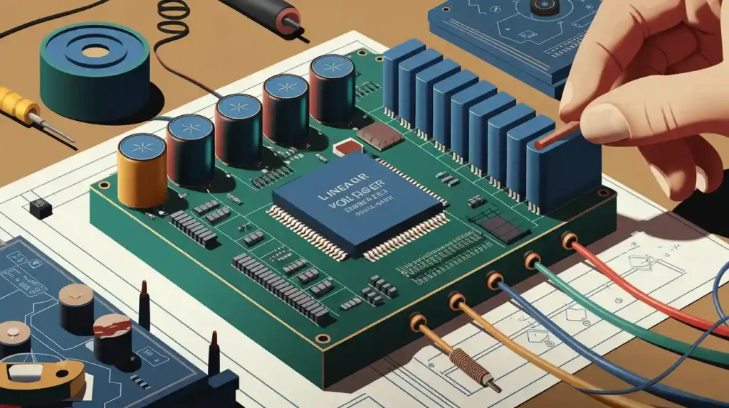
BLDC Motor Controller Circuit Design

Power Stage Components
You make the power stage with half-bridge or half-H bridge setups. Each phase uses two switches like MOSFETs, IGBTs, or GaN transistors. These switches control how current moves in the stator windings. This setup lets you power the right windings in six steps. That helps the motor work well and saves energy. Hall-effect sensors are often used to find the rotor’s position. This helps the controller turn the switches on and off at the best time. It makes the motor faster and more efficient.
Half-bridge setups make the circuit easier.
MOSFETs and GaN switches switch fast and waste less energy.
IGBTs are good for bigger motors with high voltage.
Gate Drivers and MCU
Gate drivers make the PWM signals from the microcontroller stronger. The microcontroller is the brain of the controller. It controls commutation, speed, and torque. Gate drivers help the switches turn on and off quickly and safely. Microcontrollers and gate drivers work together in many designs. This helps meet safety rules for cars. In electric vehicles, this teamwork makes the system safer and better. Companies like STMicroelectronics make drivers that work well with microcontrollers. This makes your circuit strong and efficient.
Commutation Methods
You can pick trapezoidal or sinusoidal commutation for your controller. Trapezoidal commutation powers two windings at once. This makes the circuit simple but can cause shaking at low speeds. Sinusoidal commutation uses smooth current changes. This makes the motor run better and with less shaking. Sinusoidal commutation often uses PWM for better control. This is helpful at high speeds. Tests show sine-based commutation gives smoother running and less torque ripple.
PWM and Speed Control
PWM is very important for controlling speed and saving energy. PWM changes how much current goes to the windings. Closed-loop controllers change the PWM duty cycle using feedback. This keeps the speed steady even if the load changes. Tests show fuzzy logic control (FLC) works better than PID for speed and torque. FLC gives faster starts, less overshoot, and smoother changes. Hardware tests show that good PWM and FLC make the circuit work better and more reliably.
FLC gets to the right speed faster than PID.
PWM helps control current and speed.
Smoother torque means the motor works better.
ICs vs. Discrete Components
You have to choose between integrated circuits (ICs) and discrete parts. Integrated modules save time and space but cost more and are less flexible. Discrete parts cost less and let you make custom designs. But they take longer to build and test. Integrated modules are quieter and smaller. Discrete parts spread heat better and can be changed more. Tools like TI’s WEBENCH help you compare cost, size, and performance.
Aspect | Integrated Power Modules | Discrete Component Designs |
|---|---|---|
Design Complexity | Lower | Higher |
Cost | Higher | Lower |
PCB Footprint | Smaller | Larger |
Noise Performance | Lower | Higher |
Thermal Management | Concentrated, optimized | Better distribution |
Flexibility | Limited | Greater |
Time-to-Market | Faster | Slower |
Stability | May struggle with large loads | More options |
Application Fit | Space-constrained, quick design | High-volume, cost-sensitive |
Tip: If you want to finish fast and need a small design, use integrated modules. If you want to save money and make custom changes, use discrete parts.
BLDC Controller Challenges
Making a bldc motor controller is not easy. There are many problems that can hurt how well your system works. You have to solve things like finding the rotor’s position, running without sensors, handling power, stopping noise, and picking good control methods. If you know about these problems, you can make better brushless systems for any job.
Challenges of Making a BLDC Motor Speed Controller
There are lots of problems when making a bldc motor speed controller. You need to find the rotor’s position exactly, start up without sensors, handle power and noise, and pick the best control method. Each problem can change how much energy you use and how well your brushless motor works.
Finding the rotor’s position often needs sensors. Sensors cost more and can break.
Running without sensors is hard at low speed and when starting.
Power problems can make the motor too hot and waste energy.
Noise and shaking can make the motor work worse and even break it.
Fancy control methods need careful setup and stronger hardware.
Note: Back EMF detection is the best sensorless way right now, but it does not work well at low speed. You should try new ways like flux linkage estimation or adaptive control to make your design better.
Rotor Position Accuracy
Getting the rotor’s position right is very important for a bldc motor controller. If you get it wrong, your brushless motor will not work well. Hall-effect sensors work well but make the motor bigger and cost more. Sensorless ways use the motor’s own signals to guess the position, but these are not as good at low speed.
Method/Technique | Key Improvement/Feature | Challenges/Notes |
|---|---|---|
Sliding-Mode Observer (SMO) | Lets you guess rotor position without sensors, saving money and space. | Hard to use at low speeds because of changes in the motor. |
Direct Torque Control (DTC) | Uses current and back-EMF to lower mistakes and shaking. | Can make the motor shake and switch speed a lot. |
DTC with Space Vector Modulation | Makes less shaking and keeps switching speed steady, so position is more exact. | Needs lots of computer power and can make mistakes over time. |
Stator Resistance Adaptation | Helps at low speed by guessing resistance, which is needed for good control. | Very important at low speed when resistance changes the signals. |
Saturation Effect & Short Pulse Sensing | Uses special magnetic tricks and short pulses to find rotor position and help the motor start. | Stops the motor from spinning backward or shaking when starting, and works without sensors. |
DSP-based Sensorless Control | Smart DSP chips use voltage and current to guess position. | No need for sensors, so it is cheaper and more accurate. |
New studies show that DSPs and smart models can help find the rotor’s position better. These ways use voltage and current to guess where the rotor is, even if there is noise. You can get over 90% accuracy, which helps your brushless motor work better and spot problems.
Sensorless Startup
Starting up without sensors is one of the hardest things for a bldc motor speed controller. At low speed, back EMF signals are weak, so the controller cannot see the rotor’s position well. This can make the motor miss steps, shake, or spin the wrong way.
To fix this, you can:
Use flux linkage estimation or look at inductance for better low-speed guessing.
Try short pulse sensing to find rotor position with magnetic tricks.
Mix in smart controls or AI to help the motor start better.
These ideas help your brushless motor start smoothly and save energy, even if you do not use sensors.
Power and Noise Issues
Handling power and noise is a big problem for bldc motor speed controllers. If you do not cool the motor well, it can get too hot, wear out, and waste energy. Shaking and noise make the motor work worse and do not last as long.
Aspect | Description |
|---|---|
Power/Vibration Study | Tight mounting lowers shaking and saves power. Loose motors shake more and waste energy. |
Noise Measurement | Loudest noise happens near 3 kHz from magnetic forces. Good design lowers noise but keeps torque. |
You should always bolt your motor down tight to stop shaking and save power. Use good design settings to make less noise, especially between 0.8 and 5 kHz. Testing in quiet rooms and using computer tools can help you find and fix noise. Motor control ICs, like Infineon’s MOTIX, put power, talking, and driver parts together to save energy and make your design easier.
Advanced Control Algorithms
Picking the right control method is very important for your bldc motor controller. Simple PID controllers are good when things do not change much, but they do not work well if things get weird or noisy. Fuzzy Logic Control (FLC) can handle changes and noise, but it is hard to set up. Sliding Mode Control (SMC) is strong and does not overshoot, but it can make the motor wear out faster.
Control Strategy | Key Advantages | Challenges Addressed | Limitations | Implementation Details |
|---|---|---|---|---|
PID Controller | Easy and works well when things are steady; fast to react. | Good for simple jobs; can be hard to tune. | Not good with weird changes or noise; can overshoot. | Used on Arduino Mega; tuning can be tricky. |
Fuzzy Logic Control (FLC) | Handles weird changes and noise; adapts to new things. | Good for tricky jobs; deals with noise and surprises. | Needs experts to set up rules; can be slow; not great with sudden changes. | Tested on Arduino Mega; uses rule-based logic. |
Sliding Mode Control (SMC) | Strong against changes; no overshoot; very exact. | Handles weird changes, noise, and is very steady. | Can make the motor chatter and wear out; needs careful setup. | Used on Arduino Mega; tested in labs and with computers. |
You can also use mixed controllers, like fuzzy-SMC or FOPID with smart tuning. These new ways make torque smoother, keep speed steady, and save more energy. Observer-based ways, like Sliding Mode Observers, let you run without sensors and save money. Smart tuning, like ANFIS with Elephant Herding Optimization, works better than old controllers for speed and current.
Mixed controllers make torque smoother and help with sudden changes.
Observer-based ways save money and make things more reliable.
Smart tuning changes with the load and saves more energy.
Tip: Always pick a control method that fits your job. Fancy algorithms can make your brushless motor work much better, but you might need stronger hardware and careful setup.
Now you know how BLDC motor controllers work in many places. You can make things use less energy and work better with the right control. These controllers help save power in robots, cars, and more. Always try to save energy, control things well, and get good results. To do your best, follow this short list:
Pick a controller that fits your job.
Check how much energy you use.
Adjust settings for the best results.
Look at all jobs for wasted energy.
Learn new ways to control for better results.
If your job is hard, ask an expert to help you save more energy and get better results.
FAQ
What is the main advantage of using a BLDC motor controller?
You get better efficiency and your motor lasts longer. BLDC controllers use electronic commutation, so there are no brushes to wear out. This means you do not need to fix the motor as often. You also get better control over speed and torque.
Can you run a BLDC motor without sensors?
Yes, you can use sensorless controllers for this. These controllers guess the rotor’s position by looking at back-EMF. You use less wiring and spend less money. But, the motor is not as accurate at low speeds.
How do you reduce noise in BLDC motor systems?
You should bolt your motor down tightly and use sinusoidal commutation. A good PCB layout and shielded wires help stop electrical noise. Testing in a quiet place helps you find and fix noise problems.
What happens if you use the wrong controller for your BLDC motor?
Your motor could get too hot, work badly, or even break. Always use a controller that matches your motor’s voltage, current, and commutation type. Check the datasheets before you connect anything together.
Do you need special software to program a BLDC controller?
Most advanced controllers need to be programmed. You use software from the company to set up and tune the controller. Some simple controllers work right away, but custom setups need special software.