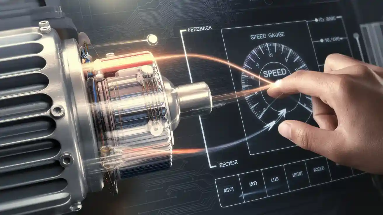
You can control the speed of a brushless dc motor by using a bldc motor controller and a PID algorithm together. This setup helps you change the controller output right away. It keeps your brushless dc motor at the speed you want, even if things around it change. You need both hardware and software for this to work.
The table below shows how using PID speed control in bldc motor controllers makes them work better:
Performance Aspect | Description |
|---|---|
Speed Regulation | Keeps speed steady when things disturb it. |
Rise Time | Makes the motor reach the right speed faster. |
Overshoot | Stops the motor from going too fast past the set speed. |
Steady-State Error | Gives correct speed for a long time. |
Key Takeaways
A PID algorithm helps a BLDC motor controller keep speed steady, even if things change. Good hardware, sensors, and firmware all work together to control speed well. If you tune the PID settings carefully, the motor can reach the right speed fast. It will not go too far or shake. Testing your controller with different loads and speeds helps you find problems early. This also makes the motor work better. Picking the right motor, controller, and feedback method saves energy. It also makes your system work well and last longer.
BLDC Motor Controllers and PID Basics
Motor Structure
A brushless dc motor has a simple design. The rotor has permanent magnets. The stator holds the windings. This design does not need brushes. Brushes wear out in other motors. The bldc motor controller connects to the stator. It controls how current flows. The table below shows key parts of the motor:
Parameter / Equation | Description |
|---|---|
Stator diameter (Ds) | Main size of the stator |
Slot cross-section (S_enc) | Area for windings, based on stator size and slot count |
Slot fill factor (k_r) | How much of the slot is filled with conductor |
Number of slots (N_e) | Total slots in the stator |
Back EMF (E) | Voltage created by the rotor’s movement |
Motor efficiency (η) | Ratio of output to input power |
A bldc motor controller uses these features to make the motor work better. It also helps the motor last longer.
Electronic Commutation
BLDC motors do not need brushes. The controller uses electronic commutation instead. It switches current in the stator windings with transistors. The controller checks the rotor’s position with sensors. These can be Hall-effect sensors or rotary encoders. Some controllers do not use sensors. They measure back EMF to find the rotor’s position. This lets you control the speed and direction very well.
Tests show that electronic commutation gives very good speed control. Models using this method match real motor speeds almost exactly. This is true even when starting, stopping, or in noisy places. This shows bldc motor controllers can do hard control jobs.
PID Speed Control
To keep the motor speed steady, you use a pid algorithm. The controller checks the speed and compares it to your goal. It changes the output to fix any difference. This closed-loop control keeps the motor at the right speed. It works even if the load changes. Studies show advanced controllers make rise time 28% shorter. They make settling time 35% shorter. Overshoot is 22% less. Steady-state error can be as low as 0.3%. This means your bldc motor controller gives fast and steady speed control for many uses.
Components for Speed Control
Motor Types
There are different brushless dc motors you can pick. Each one has special features. These features change how the bldc motor controller works. Most bldc motors use three phases. The windings can be in a star or delta shape. Star-wired motors, like Oriental Motor’s, are very efficient. They also control speed well. These motors can give up to 5159 lb-in of torque. Their power ranges from 15 W to 400 W. Picking the right motor helps your controller keep the speed steady. It also saves energy.
Controller Hardware
The bldc motor controller hardware is the main part of your system. You use pulse-width modulation, or PWM, to set the speed. The controller changes how long the voltage pulses last. Hall effect sensors inside the stator show where the rotor is. This helps the controller switch phases at the right time. You do not need power relays with this setup. This means less work to keep it running. The hardware lets you connect to programmable controllers. This design makes the system efficient and reliable. For example, the BMU Series 200 W motor and controller reach 86% efficiency. They also meet IE4 standards.
Speed Feedback Sensors
You need good feedback to keep the motor at the right speed. Many systems use Hall sensors or rotary encoders. These sensors track the rotor’s position. They help the controller change speed quickly. Some systems use sensorless control. They guess the rotor’s position by checking back-EMF or using observers. Research shows sensorless methods work well, even if the load changes fast. Observers like the Extended State Observer help block out problems. They also make speed guesses more exact. This makes your speed controller work better in many situations.
Sensorless detection works at high and low speeds.
Advanced observers lower phase delay and overshoot.
Good feedback helps the system handle all kinds of loads.
Firmware Needs
You must program the firmware in your controller. It handles all the control jobs. The firmware reads feedback from sensors or sensorless estimators. It runs the PID algorithm to keep the speed steady. Digital signal processors, or DSPs, help the controller check things fast. They also do quick math. This lets your controller react fast to changes. The firmware also controls PWM signals. It changes the duty cycle when needed. Good firmware helps your controller and motor work well together. It keeps the speed where you want it.
Tip: Always test your firmware with different loads and speeds. This helps you find problems and make your speed controller better.
Component/Method | Description and Role in Speed Control | Supporting Details and Benefits |
|---|---|---|
Rotor Position Sensors (Hall sensors, encoders) | These sensors show where the rotor is for phase commutation. They can cost more, take up space, and be hard to mount. | Using them can make the system less reliable and bigger. They also raise the price. |
Sensorless Control Techniques | These use back-EMF and observers to guess rotor position and speed. No physical sensors are needed. | They lower cost and size. They also make the system more reliable. They work well if the load does not change much. |
Back-EMF Sensing | This checks the back-EMF of a phase that is not powered. It helps find the commutation order. It is cheap but does not work well at low speeds. | You need open-loop starting. Low speeds are hard because there is no back-EMF. |
Third Harmonic Voltage Integration | This uses the third harmonic of back-EMF to guess rotor flux position. It is not as affected by filtering delays and works at many speeds. | It gives high performance and helps the motor start well at low speeds. |
Digital Signal Processors (DSPs) | DSPs run advanced control algorithms for sensorless control. They can check and calculate things very fast. | They make the system work better than regular sensor-based drives. They can remove the need for sensors by using math. |
Sliding-Mode Observer (SMO) | SMO guesses rotor position and speed. It fixes problems from nonlinearities and changes in parameters. It helps at low speeds. | It can guess stator resistance and speed on its own. It keeps the system stable and makes sure guesses are correct. |
Observers (Model-Based Methods) | Observers guess things you cannot measure, like rotor position and speed. They use system inputs and outputs. This helps closed-loop control. | They let you guess hard-to-measure things. They make control more accurate and reliable. They are needed for sensorless control. |
Stator Resistance Estimation | This is important for good low-speed work. It affects how well you can guess stator flux and speed. | Algorithms using SMO and hyper-stability theory make the system stronger against changes in parameters. |
Implementing PID in BLDC Motor Controller
Hardware Setup
First, get your hardware ready for the bldc motor controller. Pick a good brushless dc motor and a controller that uses pulse-width modulation. Use an 8-bit microcontroller, like a PIC MCU, to control the bldc. Connect the controller to the motor windings. Make sure the power supply fits your motor’s needs. Attach sensors, such as Hall sensors or encoders, to the motor for feedback.
Connect the controller’s output to the motor phases. Use transistors or MOSFETs to switch the power. Set up pwm signals to control the voltage sent to the motor. Change the pwm duty cycles to adjust the speed. Use an oscilloscope or data logger to check input, output, and error signals. This helps you see if your hardware works well.
Tip: Try your hardware with different loads. Use experiment design methods, like factorial design, to find the best setup. Statistical tools such as ANOVA help you see which factors matter most for your controller’s performance.
Sensor Integration
Sensors are important in your bldc motor controller. Hall sensors and encoders tell you the rotor’s position and speed. You can also use sensorless ways that guess position from back EMF. Connect your sensors to the controller’s input pins. Make sure the wires are tight and the sensors are set up right.
You can check how well your sensors work by looking at these things:
Metric | Description |
|---|---|
Average Velocity (V) | Shows the mean speed of your motor. |
Average Acceleration (A) | Tells you how quickly the speed changes. |
Average Trajectory Deviation (D) | Measures how close your motor follows the target speed. |
Trajectory Coincidence (C) | Shows how much the actual and target speeds match. |
Intersecting Area of Trajectory (S) | Checks how well your motor tracks the set speed over time. |
If you use machine learning models, you can guess motor function scores from these features. This helps you get good and steady speed feedback.
Note: Always check your sensor signals for noise. Bad wires or sensors that are not set up right can cause errors in your speed controller.
PID Algorithm
A pid algorithm helps your bldc motor controller keep the speed steady. The controller reads the real speed from the sensors and checks it against your setpoint. It finds the error and uses three parts: proportional, integral, and derivative. The proportional part reacts to the current error. The integral part adds up past errors. The derivative part guesses future errors.
You can write the pid algorithm in your controller’s firmware like this:
error = setpoint - actual_speed;
integral += error;
output = Kp * error + Ki * integral + Kd * (error - last_error);
last_error = error;
Many bldc motor controllers use only the proportional and integral parts. The derivative part can make the system shake, especially if there is noise. You can change the Kp and Ki values to get the best results. Start with small numbers and raise them while watching for overshoot or instability.
You can check how well your pid works by looking at these things:
Rise time
Settling time
Overshoot
Steady-state error
You can also use error-based rules like Integral Time Square Error (ITSE) or Integral Absolute Error (IAE) to see how well it works. Some engineers use special algorithms, like Genetic Algorithm or Particle Swarm Optimization, to tune the pid settings for better results.
Tip: If your controller has too much overshoot or shakes, try lowering the Kp or turning off the derivative part.
Tuning Parameters
Tuning your bldc motor controller is important for good speed control. Start by picking first values for Kp and Ki. For example, you can try Kp=5 and Ki=7. Run the motor and see how fast it gets to the set speed. If it is slow, raise Kp. If you see shaking, lower Kp or Ki.
You can use data from encoders or tachometers to check your results. Try different values and write down what happens. Use performance scores like IAE, ITAE, ITSE, and ISE to compare settings. These scores help you find the best tuning for your speed controller.
You can also use math equations for torque, angular velocity, and current to model your brushless dc motor. This lets you test changes in tuning and see how they affect speed control.
Tip: Always test your tuning with real hardware. Simulations help, but real tests find problems you might miss.
Testing and Troubleshooting
Testing your bldc motor controller helps you find and fix problems. Use sensors and data loggers to record input, output, and error signals. Watch for trouble, like actuator saturation, integral windup, or noise sensitivity.
Here is a table of common issues and what to check:
Category | Description / Purpose |
|---|---|
Error Signals | Look for large or growing errors between setpoint and actual speed. |
Actuator Saturation | Check if the controller output hits its maximum or minimum. |
Integral Windup | Watch for slow response or overshoot caused by too much integral action. |
Noise Sensitivity | See if high-frequency noise makes the controller unstable. |
Bias | Look for steady-state errors that do not go away. |
Nonlinearity | Notice if the system behaves differently at different speeds or loads. |
Sensor Calibration | Make sure sensors give accurate readings. |
Actuator Health | Confirm that the motor responds to controller commands. |
Feedback Loop Integrity | Ensure feedback signals match the real state of the system. |
PID Parameter Tuning | Review your Kp, Ki, and Kd values for stability and performance. |
If you see problems, change your tuning or check your hardware. Make sure your pwm signals and duty cycle are correct. Test your controller with different loads and speeds to make sure it works in all situations.
Tip: Use closed-loop simulations before hardware tests. This helps you find problems early and saves time.
Speed Controller Tips and Challenges
Current and Voltage
You must check current and voltage in your bldc motor controller. Using the wrong voltage can stop or break your bldc motor. The table below shows safe voltage and temperature for your controller:
Input Voltage (VDC) | Operational Result |
|---|---|
8 – 30 | Normal operation |
>= 42 | Energy Dump error; motor stops and freewheels until power cycle |
Temperature (°C) | Current Limit Behavior |
|---|---|
< 75 | Normal operation |
75 – 90 | Current limits scale down to 40A at 90°C |
90 – 100 | Current limit capped at 40A |
>= 100 | Motor stops; freewheels until reset |
You should set surge current limits too. If the surge current limit is higher than normal, your controller lets short high current bursts happen. This helps your bldc handle quick load changes.

Switching Frequency
Switching frequency changes how your bldc motor controller works. Raising the switching frequency makes the current smoother. This helps your bldc run quieter and gives better torque. Tests show higher switching frequencies make control bandwidth bigger. For example, 8 kHz switching can raise bandwidth from 400 Hz to 1 kHz. You get faster response and better speed control. But if the frequency is too high, your controller can get hotter.
Position Detection
Good position detection is important for your bldc motor controller. You can use full step, half step, or microstepping. Microstepping gives the best precision but less torque. Chopper drive drivers help you control current better. This makes your bldc run smoother and helps with position control. If you use current-limiting drivers, you might lose some precision and efficiency.
Mode | Precision | Torque |
|---|---|---|
Full Step | Low | High |
Half Step | Medium | Medium |
Microstepping | High | Low |
Firmware Issues
Firmware problems can make your bldc motor controller fail. You should use tools like oscilloscopes to check signals. Look at memory and registers to find mistakes. Real-time trace analysis helps you see timing problems. Automated testing finds bugs early. Some companies had big trouble because of bad firmware. For example, stack overflows and missing fail-safes made them lose control. Always test your firmware and use safe coding rules.
Common Pitfalls
You may run into common problems when tuning your bldc speed controller. Many people use trial and error to set PID values. This can give bad control. Fixed PID settings do not work well if your system changes. Heuristic methods like Ziegler-Nichols are easy but not always strong. Adaptive PID needs good models, which are hard to get. You should use measurement system analysis and control charts to watch performance. Always collect data, check your process, and keep learning.
To set up PID speed regulation in your BLDC motor controller, follow these steps:
Choose the right controller hardware.
Connect sensors for feedback.
Program the controller with a PID algorithm.
Tune the controller for best results.
Test the controller with your BLDC motor.
Keep learning and ask for help if your controller faces complex problems. You can achieve steady speed and reliable control.
FAQ
What does PID stand for in motor controllers?
PID stands for Proportional, Integral, and Derivative. These three parts help you control the speed of your BLDC motor. Each part fixes different types of errors in your speed control system.
Why does my BLDC motor overshoot the target speed?
Your motor overshoots when the PID settings are too high. Try lowering the proportional (Kp) or integral (Ki) values. This helps your motor reach the target speed without going too far.
Can I use sensorless control for all BLDC motors?
You can use sensorless control for many BLDC motors. It works best at medium and high speeds. At very low speeds, sensorless methods may not give accurate rotor position.
How do I know if my PID tuning is correct?
Check these signs:
The motor reaches the set speed quickly.
There is little or no overshoot.
The speed stays steady.
If you see large errors or shaking, adjust your PID values.