That constant hiss in your TWS earbuds? That buzz when Wi-Fi fights with your bluetooth audio transmission? These problems bother modern portable speakers. You face a big engineering question: how do you get a noise floor below -90 dB without hurting audio quality or causing sync errors?
Wi-Fi interference breaks up your wireless link. Class-D amplifier switching noise leaks into delicate circuits. Your bluetooth speaker circuit design struggles with RF coupling from the 2.4 GHz transceiver. Every bluetooth audio transmission carries unwanted noise that lowers sound quality.
This guide gives a clear, part-by-part plan. Learn useful ways to cut noise in wireless audio systems. Look at filter parts, power supply separation, and PCB layout that protect sound during bluetooth communication. Expect real fixes for your next wireless signal design. Your bluetooth speaker circuit deserves better.
Key Takeaways
Use MAF filters on speaker lines and AVRF filters on microphone lines to stop RF noise from getting through.
Use DC-DC converters and LDOs to separate the power supplies and cut down hiss and hum.
Keep a solid ground layer and add via stitching to stop radio frequency leaks.
Put the antenna at least 10 mm away from audio parts to avoid interference.
Pick a 2nd or 3rd order filter to balance reducing noise with keeping good sound quality.
Noise Sources in Bluetooth Audio Transmission
Noise gets into your bluetooth audio receiver through three main paths. Each path touches different parts of your circuit. Knowing these paths helps you focus your noise reduction work. The table below shows the main ways noise enters your system.
Primary Ingress Path | Mechanism of Noise Ingress | Affected Component |
|---|---|---|
Wired speaker lines | RF signals from the antenna get picked up by PCB traces and transposed onto audio lines | Speaker output circuit |
Wired microphone lines | Bluetooth RF signal transposes onto microphone wiring, forming an envelope waveform | Microphone input circuit |
Antenna-to-wiring coupling | Close physical proximity causes electromagnetic coupling, degrading RF sensitivity | Antenna and audio lines |
RF envelope waveform generation | Non-linear amplifier effects create an audible-range envelope from the RF signal | Audio amplifier and speaker |
Harmonic noise from digital amplifiers | Switching harmonics radiate and interfere with RF signals to and from the antenna | Digital amplifier and antenna |
RF Coupling and Antenna Desense
Your antenna and audio traces often sit close together on a typical bluetooth audio receiver board. This closeness creates a big problem. The antenna sends out a 2.4 GHz signal during bluetooth communication. Nearby PCB traces act like extra antennas. They catch this RF energy and move it onto your audio lines. The result reaches your speaker output circuit as unwanted noise.
Antenna desense makes this issue worse. When audio wiring couples electromagnetically with the antenna, your receiver loses sensitivity. You see dropped packets and weaker bluetooth signal reception. The coupling also adds noise directly into your audio path. You must keep these parts apart physically to protect wireless audio reception quality.
Amplifier Harmonics and Envelope Noise
Digital amplifiers create switching harmonics during normal operation. These harmonics spread out from the amplifier circuitry. They disturb RF signals going to and from your antenna. Your bluetooth communication suffers from more error rates. The disturbance also lowers your overall wireless performance.
Non-linear effects in your audio amplifier create another noise source. The amplifier makes an envelope waveform from the bluetooth RF signal. This envelope sits within the audible frequency range. Your speakers then play this envelope as audible noise. You hear it as a steady buzz or hiss during quiet parts. This problem affects both speaker output and microphone input circuits. Your microphone wiring catches the RF signal and makes its own envelope waveform. That waveform enters your audio processor and ruins your recording or voice transmission.
Filtering for Bluetooth Audio Receiver Circuits
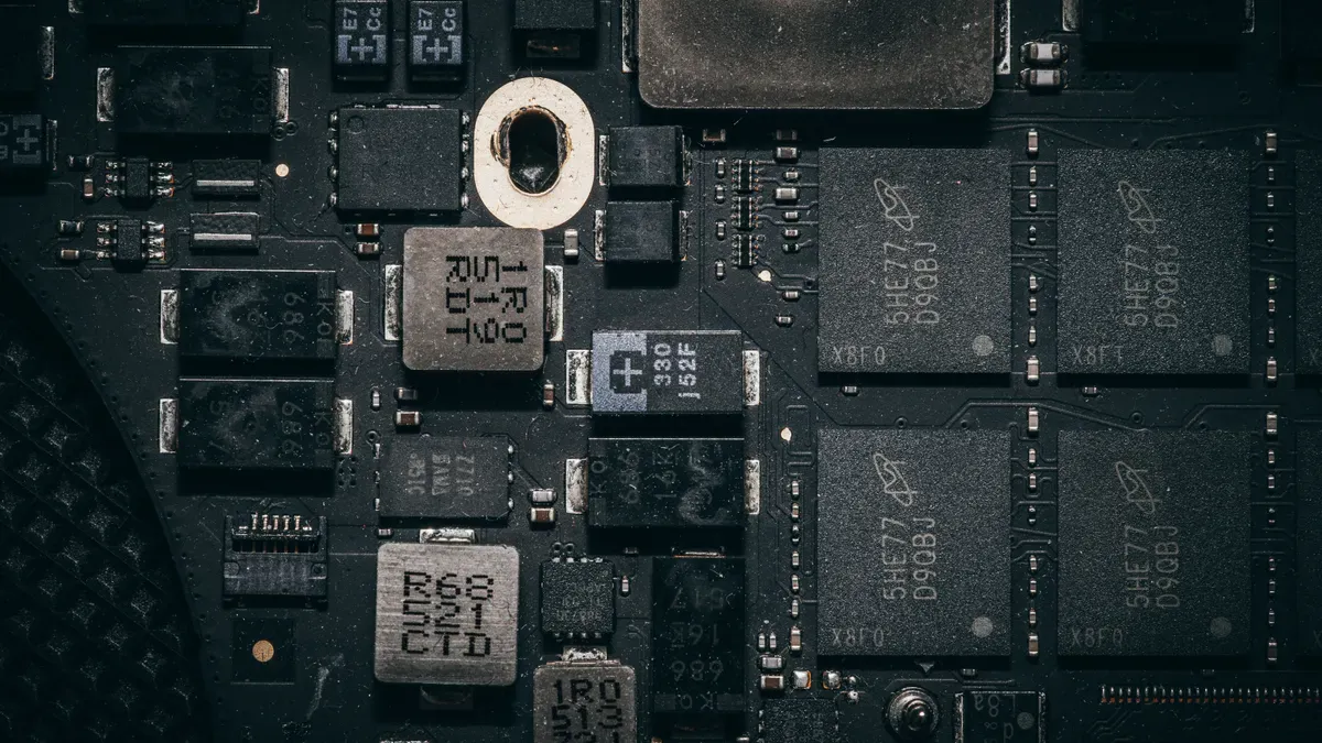
You need the right filters to keep noise out of your audio path. Good filter parts block RF energy but let your music pass through clearly. The parts you pick set your final noise level.
MAF and AVRF Filter Implementation
Start with your speaker output lines. Murata MAF series filters work well here. These parts have insertion loss below 0.5 dB at 1 GHz. That means they stop high-frequency noise without hurting your audio signal. Put one MAF filter on each speaker line between your bluetooth audio ic and the amplifier input. This stops RF energy from moving down the speaker wires.
Your microphone lines need a different fix. The AVRF series from Murata handles this job well. Microphone wiring picks up RF signals easily because of its length and path. The AVRF filter removes that RF energy before it reaches your audio processor. Install these filters right at the microphone input connector. This spot catches noise at the entry point before it spreads through your circuit.
Think about the filter cutoff frequency carefully. Your audio band goes up to about 20 kHz. The filter must let this whole range pass. At the same time, it must block the 2.4 GHz bluetooth carrier signal. A wide gap exists between these frequencies. This gap gives you design freedom. You can pick a filter with a slow roll-off without hurting audio quality. A second-order filter often gives enough blocking for consumer devices. Higher-order filters add complexity without much benefit in most bluetooth audio receiver designs.
Test your filter setup with a spectrum analyzer. You want to see at least 30 dB of blocking at 2.4 GHz. Measure the insertion loss at 1 kHz and 10 kHz to confirm your audio passes cleanly. Write down these numbers for your design review. This check finds layout problems before you start production.
Power Supply Noise in Bluetooth Speaker Circuit
Your power supply adds noise into the audio path. Switching regulators create ripple at their switching frequency. This ripple leaks into your analog audio rails and makes audible hiss. You have two solid fixes for this issue.
First, use an isolated DC-DC converter like the B0505s. This part separates your ground rails completely. The isolation stops ground bounce from the digital section reaching your analog parts. Connect the isolated output only to your audio amplifier and codec. This separation removes a major noise path in your bluetooth speaker circuit.
Second, choose LDOs over switching regulators for analog audio rails. LDOs make much less ripple than switching converters. A good LDO gives clean power with very little noise. You lose some efficiency compared to a switching regulator. For battery-powered devices, this trade-off matters. But the better audio quality makes up for the efficiency loss in most designs.
Your bluetooth speaker circuit works best with a mix of both. Use a switching regulator for digital rails. These rails can handle more ripple. Use an LDO for analog audio rails. This mix gives you efficiency where you need it and clean power where you must have it. Put a ferrite bead between the LDO output and your audio codec power pin. This bead filters any leftover high-frequency noise.
Remember that power supply filtering works with your signal line filters. Both methods reduce noise in your bluetooth audio transmission. You need both for a full fix. A clean power supply with noisy signal lines still makes audible problems. And filtered signal lines with dirty power still suffer from hum and buzz. Fix both paths to cut noise well in your wireless audio system.
Your receiver design must handle all these factors together. The filter parts, power setup, and layout choices work as one system. Each part supports the others. When you balance all three, you get the low noise floor your customers expect from modern bluetooth audio products.
Noise vs. Audio Quality Trade-offs in Bluetooth Audio
You have to balance two things when you design filters for your Bluetooth audio receiver. Every filter you add to block noise also changes your audio signal. The main question is: how much filtering is too much? Your answer decides if your product sounds clear or dull.
THD+N and Insertion Loss Analysis
Total harmonic distortion plus noise, or THD+N, measures the unwanted sounds in your audio output. Engineers calculate this value by taking the root mean square sum of all signal parts except the main frequency over a set range. To match what people hear, they often use filters like ITU-R 468 to focus on frequencies inside the human hearing range. This method gives you a real picture of what listeners actually hear.
Your filter choice directly affects THD+N. If you set the filter cutoff too close to the 20 kHz audio band edge, you start removing sounds people can hear. This action increases distortion because the filter weakens parts of the music signal itself. For high-quality designs, you should aim for THD+N below 0.01%. That number means a clean signal path with very little added noise.
The bitrate of your Bluetooth audio transmission also affects distortion levels. At 303 kbps, the frequency response drops around 16.5 kHz, limiting high-frequency sounds. Noise becomes higher at higher frequencies, hurting THD+N for complex signals above 10 kHz. When you move to 606 kbps, the frequency response extends to 20 kHz, reducing high-frequency noise and improving multitone distortion. However, the 1 kHz THD+N stays similar to 303 kbps for simple signals. At 909 kbps, the frequency response stays full at 20 kHz, and THD+N improves by about 3 dB over 606 kbps. High-frequency distortion drops more, with problems mostly above 15 kHz.
These numbers show a clear pattern. Higher bitrates give you more room for filtering without hurting audio quality. You can use stronger filters at higher bitrates because the signal carries more information. At lower bitrates, you must use gentler filters to keep what little high-frequency content exists.
Group Delay and Transient Response
Group delay describes how long different frequencies take to pass through your filter. A steep filter, like a 4th order design, creates notable phase distortion. This distortion affects transient response in percussive audio. Drum hits and sharp attacks lose their impact because different frequency parts arrive at different times.
You hear this effect as smeared or softened transients. A snare drum loses its crack. A guitar string sounds less clear. The music feels less lively and engaging. This problem gets worse as you add more filter stages.
For most consumer uses, you should pick a balanced filter order. A 2nd or 3rd order filter gives enough noise blocking without adding audible phase distortion. These filters roll off slowly enough that group delay stays low across the audio band. You lose some high-frequency noise rejection, but you gain cleaner transients and better overall sound.
Your Bluetooth audio IC handles the digital signal processing, but the analog filter sits between the DAC output and your amplifier. This analog stage shapes what listeners hear. Test your filter with square waves to check transient response. A clean square wave with little ringing means good phase behavior. Too much overshoot or ringing tells you the filter adds too much group delay.
The trade-off between noise and audio quality needs careful measurement. Use FFT analysis to see the noise floor across the audio spectrum. Compare THD+N readings with different filter setups. Listen to percussive tracks to check transient response. Your ears are still the final judge, but measurements guide your choices. Finding the sweet spot between noise suppression and audio fidelity takes testing, but the result gives the sound quality your customers expect from modern wireless audio products.
Bluetooth PCB Layout and Shielding for 2026
Ground Plane Partitioning and Via Stitching
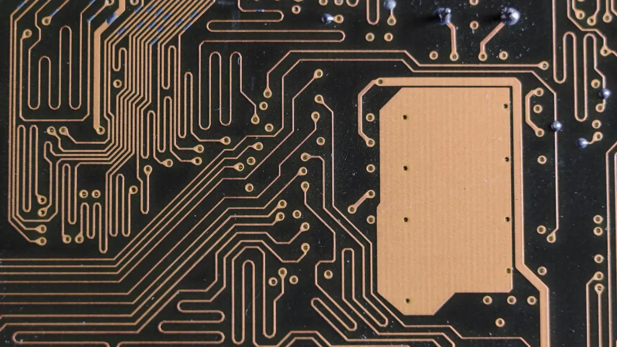
Your ground plane design controls how much noise reaches your audio circuits. Do not split the ground plane. A split ground plane disrupts return paths and creates a slot antenna effect. Use a single continuous ground plane. Partition your board by component placement. Keep RF, digital, analog, and power sections separated. Place your bluetooth audio ic in one area. Place your audio codec and amplifier in another area. Decouple aggressively at every power pin. Keep the Class-D amplifier output loop small. Route speaker output traces away from the antenna feedline and codec inputs.
Via stitching creates an electromagnetic wall around your RF section. When the pitch is smaller than λ/20, the wave sees the vias as a solid barrier. For 2.4 GHz bluetooth, λ is about 125 mm. The λ/20 value gives a maximum spacing of about 6.25 mm. Use a tighter spacing of ≤3 mm. This prevents RF leakage into your audio traces. Place these vias around the perimeter of your RF section. Space them every 3 mm along the edge.
TWS Synchronization and Antenna Isolation
Your antenna needs separation from sensitive audio components. For TWS earbuds, place the antenna at least 10 mm away from the audio codec and amplifier. Use a metal shielding can over the RF section if your space allows. The can contains RF emissions and blocks external interference. This protection keeps your bluetooth communication and wireless link stable.
Battery current draw affects ground bounce in your system. The battery delivers high current pulses to the amplifier during loud passages. This current creates voltage differences across the ground plane. These differences shift the ground reference for your audio codec. You hear this shift as noise. Place your battery connection close to the power input of your amplifier. Keep the ground return path short and wide. Use multiple vias to connect ground planes between PCB layers.
Use a 4-layer stackup for your bluetooth audio receiver. Put RF signals on the top layer. Use a continuous ground plane on layer 2. Place power distribution on layer 3. Put low-speed digital on the bottom layer. Keep RF traces short and use 45° bends. Avoid parallel routing with digital signals. Follow 3W spacing rules. Minimize vias on RF paths. These practices prevent high-frequency noise from leaking into your audio traces, improving wireless performance.
To stop noise in your bluetooth audio transmission, you need a full plan. You have to use MAF and AVRF filters, isolated DC-DC converters, and good PCB layout. Each part helps the others. Your bluetooth speaker circuit requires this whole strategy.
The 2026 design world needs you to manage noise ahead of time. Thicker RF spaces and faster data rates cause more problems. You must check your designs with FFT analysis. Try many filter setups to find the best mix of noise blocking and sound quality.
These methods will become part of future bluetooth audio receiver and speaker circuits. Your wireless products will give cleaner sound. Your customers will notice the change in every wireless audio transmission.
FAQ
Which filter should I choose for my speaker lines?
Use Murata MAF series filters for speaker output lines. These parts block RF energy while keeping insertion loss below 0.5 dB at 1 GHz. Place one filter on each speaker line between your bluetooth audio IC and the amplifier input. This setup stops unwanted noise from reaching your speakers.
How do I clean up power supply noise in my bluetooth speaker circuit?
Use an isolated DC-DC converter like the B0505s to separate ground rails completely. For analog audio rails, choose LDOs over switching regulators. LDOs produce much less ripple. Add a ferrite bead between the LDO output and your audio codec power pin for extra filtering.
What causes the hiss I hear during quiet passages?
The hiss comes from RF coupling between your antenna and audio traces. The 2.4 GHz signal from your bluetooth transceiver gets picked up by nearby PCB traces. This energy moves onto your audio lines. Non-linear amplifier effects also create an envelope waveform within the audible range.
How far should I keep the antenna from audio components?
Keep your antenna at least 10 mm away from the audio codec and amplifier. This separation prevents electromagnetic coupling that degrades RF sensitivity. Use a metal shielding can over the RF section if space allows. This protection keeps your bluetooth pairing stable and your audio clean.
Does stronger filtering always improve sound quality?
No. Aggressive filtering can increase THD+N if the cutoff sits too close to 20 kHz. A 4th order filter creates phase distortion that smears percussive transients. For most consumer devices, use a 2nd or 3rd order filter. This balance blocks noise without hurting audio fidelity.