Why do PCB design need assembly analysis? It is to consider PCB assembly in the early design stage to get the best product.
There is a common problem that may be less common among PCB design masters, but it is still common for novices, that is, the initial circuit board design does not fully consider the assembly. On the contrary, more attention is paid to the PCB itself, and there is no extensive understanding of the problems in the manufacturing process, which leads to product design failure.
The following is an introduction to the data files that need to be prepared before assembly analysis!
1. PCB/ODB files
1) PCB file:
First open the DFM software, click “File” to find the file to be used, click Open and wait for the software to automatically parse it before using it. Or open the software and drag the file into the software graphics window to open the file.
2) ODB file:
If there are a lot of files, you can directly drag the folder into the software graphics window and wait for the software to automatically parse it! You can also drag the compressed package with the suffix tgz format into the software graphics window to open the file.

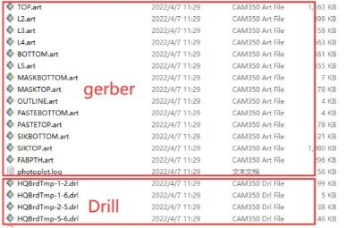
2. Gerber Files
1) Gerber files are plate-making files output from EDA software, and the files include drilling layer, inner/outer circuit, solder mask layer, silk screen layer, and board frame layer.
2) When DFM software opens Gerber files, if it is a compressed package, it needs to be decompressed before it can be opened. Gerber files have many layers and all the files inside need to be opened. If you use the menu bar “File → Open” method, you need to select all files, or you can drag the folder into the software window to parse and open the file.
3. PCB and ODB Files vs. Gerber Files
1) PCB and ODB files do not require coordinates and BOM files, because PCB and ODB have their own coordinates and BOM data.
2) Coordinates and BOM file data are required for Gerber file assembly analysis and BOM matching. The data needs to be output from the EDA software and then imported into the DFM software for assembly analysis and BOM matching.
Assembly analysis setting operation process:
After the data file is prepared before assembly analysis, assembly analysis settings can be performed.
Gerber/Drill file:
It is a PCB plate-making file generated from EDA software. Gerber/Drill file has no coordinates and BOM data, so it is necessary to export coordinates and BOM from EDA software before BOM table can be sorted and matched with component library for assembly analysis.
PCB/ODB file:
It is a design file saved by EDA software. This file has its own coordinates and BOM, which can be directly sorted with BOM table and matched with component library for assembly analysis.