You complete set-top box system integration by successfully joining main PCBAs, delicate cable harnesses, protective cases, initial firmware flashing, and automated functional testing. Electronics makers know the value of an effective box build assembly process during high-volume factory production runs. Learning this box build assembly helps you remove thermal heat bottlenecks, shorten overall lead times, and lower major manufacturing risks. As hardware density grows, you must balance complex component layouts with fast, repeatable quality assurance procedures. Managing every physical assembly detail correctly protects your final product quality, lowers total operational costs, and guarantees ultimate satisfaction for all your target end customers.
Key Takeaways
Choose aluminum casing materials with equal wall thickness to boost heat movement and stop plastic shaping errors.
Check circuit boards and wire harnesses early with automated tools to stop bad parts from reaching the assembly line.
Keep power wires away from data lines and tie groups together to prevent interference and guard delicate solder points.
Use automatic feature and heat tests on each device to find broken parts before sending the final product out.
Put completed boxes into special static-safe bags with soft foam to protect them from harm during shipping.
Planning for Set-Top Box Box Build Assembly
Enclosure Selection and DFM Principles
Use early Design for Manufacturing rules when choosing your box housing. Pick case materials wisely so internal heat flows out of the main unit smoothly. Aluminum clears away heat about 3.5 times faster than stainless steel does. A dark steel box absorbs light energy very quickly when sitting in sunlight. That trapped heat boosts inner box temperatures by 15–20°C before internal parts even power on. Shiny outer finishes reflect sun rays and shield fragile inner hardware.
Make plastic housing walls even while molding your box shapes. Keep regular wall thickness between 2.0–3.5 mm when working with ABS plastic materials. Equal wall thickness stops ugly sink spots, inner air gaps, and bent shapes. Add side draft angles of 1° for hidden walls and 1.5–2° for outer visual surfaces. Use 3° angles for rough walls. Good draft angles ensure smooth parts popping out, raise build success, protect quality, and make factory tools last longer.
Hardware and Wire Harness Preparation
Organize your factory stock carefully before starting full box assembly steps. Check every circuit board fully before starting physical installation tasks. Automated Optical Inspection finds 98–99% of surface errors on board parts. Human eyes catch only around 80% of those exact same mistakes. Spotting board errors quickly guards your high product quality standards. You avoid putting bad circuit boards inside your finished metal box frame.
Check cable harnesses and metal hardware before starting final box assembly work. Examine stripped wires closely under magnifiers to spot damaged metal strands. Use crimp force checkers to prevent loose wire ends during cable harness making steps. Connector locks and pin pull checks stop loose wires inside plastic wire blocks. Run 100% electrical flow tests to fix wrong wire paths. These early prep steps speed up production lines by cutting late repair work.
The Set-Top Box Build Assembly Process

PCBA and Power Supply Integration
You begin production by fastening the main board into the lower chassis. Assembly workers align mounting holes over metal standoffs to avoid board stress. You tighten small screws using set torque tools to secure the board. This step stops board cracks, protects weak solder joints, and ensures long-term stability during operation.
Next, you install the internal power supply unit inside its chassis bay. Good power units need key features to shield weak box parts:
Heat protection that stops unexpected internal temperature spikes
High energy savings during long system operating hours
Flexible power support for different global electrical grids
Connecting power units to main boards needs good noise control during assembly. Use star grounding by running all ground wires to one spot. This setup stops bad ground loops. Put tiny 100nF capacitors near power pins to clean fast voltage noise on critical board areas. Keep high-voltage grounds apart from low-voltage grounds to stop voltage shifts. Keep trace lengths under 5mm to cut trace resistance. Strong ground planes lower circuit resistance, keeping signals clean and improving overall device reliability.
Cable Routing and Housing Integration
You plug in wire bundles after securing main circuit boards inside the frame. The box build process needs strict wire routing in small cases. Neat wire placement directly helps heat cooling, stops noise, and makes repairs easier. Good routing lets workers check parts easily without disturbing nearby wires, which speeds up factory repairs.
You make products more reliable by using smart cable layout rules:
Keep power lines far from fast data lines to cut noise.
Fasten cable bundles using plastic clips to prevent wire rubs on sharp metal edges.
Keep air paths clear so heat sinks can cool the system properly.
You move assembly forward by readying the outer box for final closing. Check every wire path carefully before sealing the outer unit. Pinched wires between plastic case walls cause broken copper strands and short circuits. Leave extra wire slack near plugs so shaking will not break weak solder joints.
You secure the top case onto the bottom frame using screws or snap joints. Proper sealing stops outside dust and water while holding internal parts firmly. Doing every step carefully protects internal parts from early failure during use. You get high build quality while creating a smooth manufacturing workflow across the entire factory floor.
Testing Protocols for Successful Box Build Assembly
Firmware Flashing and Functional Testing
You install starter software onto every build to prep internal hardware parts for everyday use. Production workers run a simple software setup process during box build assembly steps:
Grab the correct system firmware file (
.image) from the main site and copy it onto a FAT32 USB drive.Put the USB drive into the set-top box port, turn on the power, and press the menu key for options.
Scroll through the recovery menu screen, open the software update section, and start the system file flash routine.
Let the setup run for 5 to 10 minutes, making sure nobody pulls the power plug during this active time.
Warning: Updating software can turn portal blocks back on, so test one unit before updating all factory production runs.
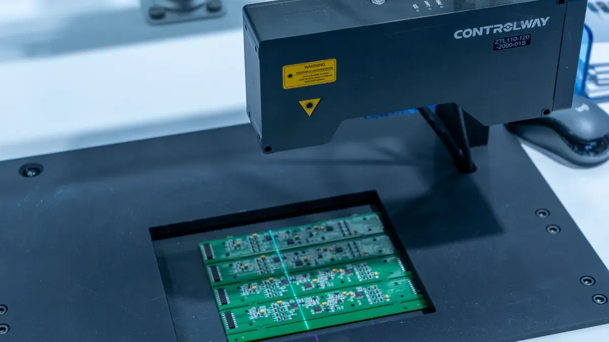
Making this software setup standard across factory lines stops user setup mistakes, cuts software bugs, and speeds up unit prep. Automated testing checks physical plug ports and running software without slowing down daily factory work outputs. New test systems compare live unit signals against older test results. This constant data review finds common broken parts fast and helps factory workers locate hidden link problems. Smart test software performs live checks on video display size, sound decoding, signal timing, and active network links. Also, automated test systems run loop checks on network ports, card slots, and wireless chips to ensure smooth streaming. You check for steady network links, clear video playback, and proper power responses before moving units to the last build station.
Burn-in Testing and Signal Verification
You test fast signal paths to keep product quality high across every build group. Special signal tools check screen output diagrams to confirm power levels and official match standards:
Send a
PRBS9test signal pattern through connected cables at set speed rates.Check side eye space and tall eye space against set boundaries to score signal clarity.
Adjust auto signal drops from 0 to -15 dB for HDMI ports or -3.5 dB for USB links.
Run extra electrical checks including wire path tests, line resistance, and marker checks.
Standard match tools test frequency and time shifts to find tiny signal drops along board lines. Next, you move every closed box into hot test ovens to run heat stress tests. Heat stress testing forces weak parts to break inside the factory instead of at home. Test workers track signal shakes, signal drops, line noise, and cross noise during long oven test runs. Later, factory workers do a required quality check to view physical port alignment, clear labels, and full outer box strength. Running a complete final check makes sure every finished box build unit handles hard daily home use. Tough checks cut return rates, guard customer trust, and raise good unit counts across all factory work shifts.
Resolving Assembly Challenges and Packaging
Thermal and Compatibility Management
Small case spaces bring common problems during final product builds. Tight boxes trap heat near working parts, and tiny build errors cause poor part alignment. You fix these heat problems by putting thick cooling pads right between hot chips and the outer metal box. Also, lining up parts carefully during final assembly stops frame stress, removes bad board gaps, and protects weak inner links.
You need to control part sizes strictly to shield inner set-top box parts. Weak solder points crack when circuit boards bend inside small case slots during building steps. You stop frame stress during board builds by following clear IPC-A-610 Class 2 rules across all factory lines. Matching case sizes helps heat leave smoothly, cuts inner hot spots, eases total build work, and keeps devices working long.
Final Packaging and Distribution Prep
Each done unit goes through a last check before entering the packing area. Factory workers check port alignments, clean outer box surfaces, and place clear protective films on display screens. This strict check shields unit surfaces from random scratches during shipping while keeping overall product quality high across every build group.
Workers place each done unit inside a custom box together with main system extras. You put remote controls, power units, and fast video cables inside the primary retail box.
Wrap the main unit in a anti-static sleeve to block static electricity.
Put shaped foam end caps inside the box to take hard hits.
Place user guides, small batteries, and setup wires into marked inner slots.
Seal the printed retail box using strong security tape.
Lastly, factory teams put several retail boxes into thick cardboard shipping cases for final delivery. Workers stick readable code labels with serial numbers and delivery addresses onto main boxes. This simple packing process protects weak electronics during global shipping, stops physical transport damage, and speeds up storage work for large factory partners.
You streamline your set-top box box build assembly process to boost overall quality and reduce operational costs. Combining early design rules, smart thermal cooling, and rigorous testing directly protects your hardware during daily factory assembly. These integrated steps optimize every manufacturing process while driving consistent, reliable product performance in the field.
You gain maximum market value by bringing these proven methods into your active production runs. Experienced contract partners help you master physical box assembly tasks, improve output yields, and secure ultimate customer satisfaction. Partnering with skilled electronics specialists elevates your total box build assembly results across every single factory shift.
FAQ
How do you optimize enclosure selection for set-top box integration?
Choose case materials with high heat flow to draw warmth away from working parts. Keep plastic wall thickness even, between 2.0 and 3.5 mm. Correct side slopes stop box molding flaws and smooth out your build process.
Why should you follow IPC-A-610 Class 2 standards during production?
Follow IPC-A-610 Class 2 standards to stop physical frame pressure on inner circuit boards. Sticking to these rules prevents solder joint cracks inside tight cases. This step raises total product quality across large factory runs.
What role does automated testing play in set-top box production?
Automated testing checks sound and video signals, plug links, and software setups without slowing work lines. You spot early part failures fast. This steady process cuts customer returns and shields your factory output.
How do you prevent cable damage inside a compact housing?
Route power lines away from data paths and lock cable bundles with plastic clips. Check wire paths before closing the outer box frame. Leaving a little extra wire slack near plugs stops stress on weak solder joints during build work.