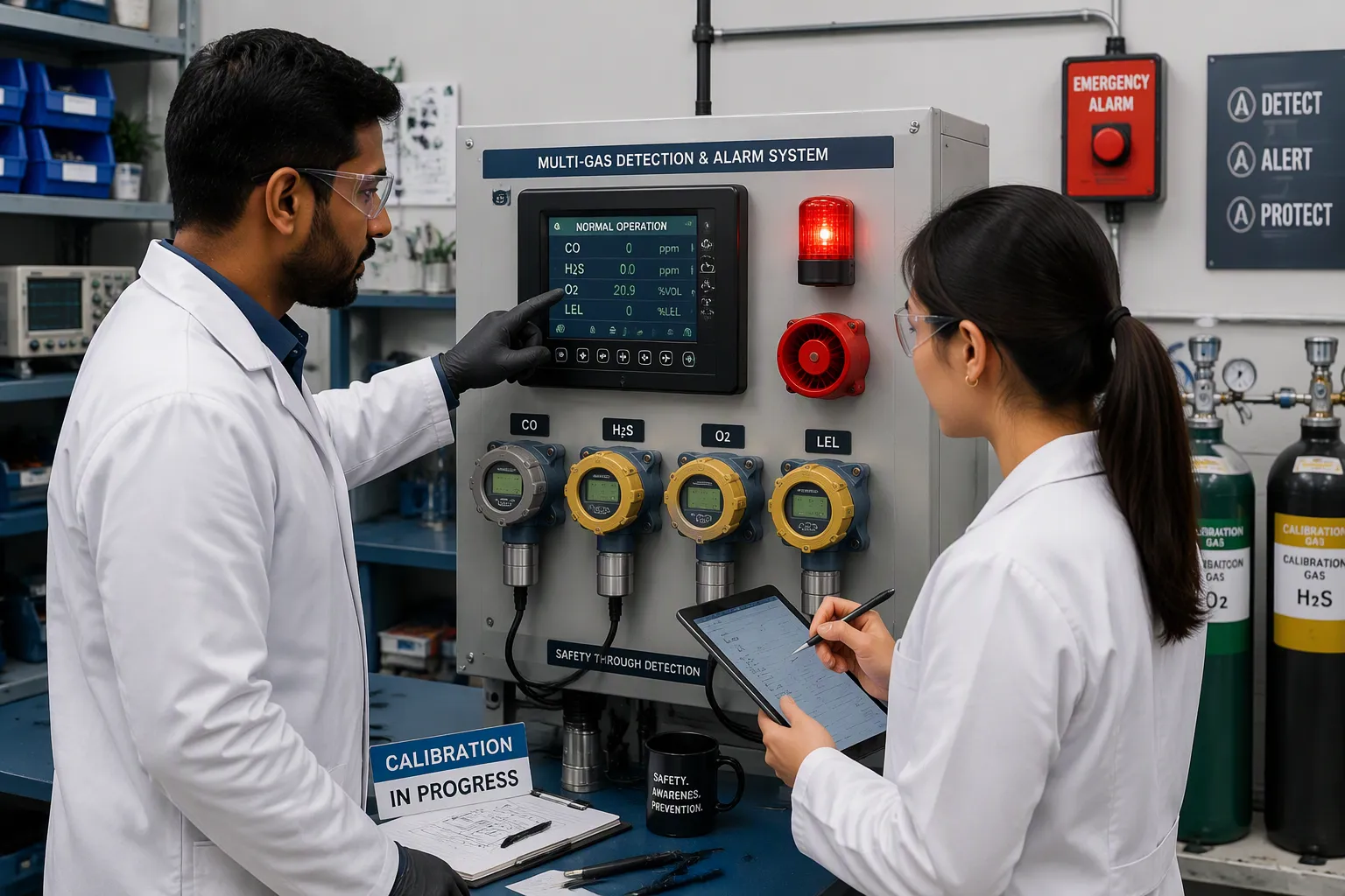
A multi-gas sensing and alarm system is a hardware platform with several sensing channels. It keeps checking multiple gases and sets off alarms at set limits. Consider a four-gas setup that tracks these channels:
Oxygen (O₂), with low oxygen flagged below 19.5%
Combustibles (LEL), with a low alarm at 20% LEL and a high alarm at 50% LEL
Hydrogen sulfide (H₂S), with a 10 ppm ceiling limit
Carbon monoxide (CO), with a 35 ppm exposure limit
A single-gas detector misses most of these dangers. Fixed units and portable multi-gas detectors share the same board-level challenges. You must master sensor technologies, the signal chain, alarm logic, and manufacturing trade-offs to build reliable gas detection and alarm systems.
關鍵要點
A multi-gas system has 四個主要部分: sensors, signal conditioning, a microcontroller, and alarm output. Each part must work well for the system to be reliable.
Pick the right sensor for each gas. Electrochemical sensors work well for toxic gases. Catalytic sensors work well for combustible gases. NDIR sensors do not use up chemicals.
Calibrate on a regular basis and adjust for temperature and humidity. This cuts down on false alarms and keeps readings accurate.
Set alarm thresholds based on safety standards. Add hysteresis and latching to prevent alarm chatter and make sure critical alarms are acknowledged.
For battery-powered designs, balance duty cycle and response time. A short active window saves power, but it must be longer than the sensor’s thermal time constant.
Multi-Gas Sensing System Architecture
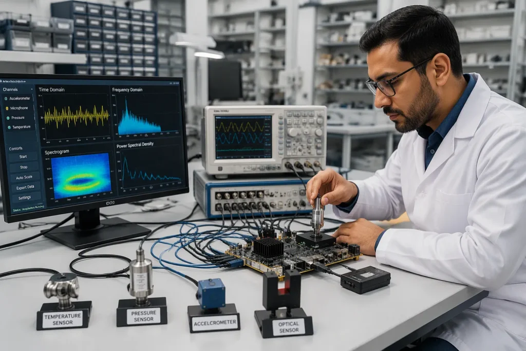
Every multi-gas sensor system is built on four main blocks. A sensor array holds the separate channels. A conditioning stage turns tiny sensor currents into voltages you can use. An MCU changes those voltages into gas concentrations and runs the alarm logic. An output stage drives buzzers, relays, and status LEDs. You should trace each block as a chain, because one weak link anywhere limits the whole multi-gas sensing platform.
Sensor Array and Signal Conditioning
Electrochemical cells in a multi-gas sensor output currents in the pA-to-µA range. A transimpedance amplifier turns that current into a voltage, and a gain stage scales it to the MCU’s input range. Keep the feedback resistor close to the amplifier and guard the input traces against leakage. Bias and warm-up sequencing matter just as much. Biased sensors need about 6 hours or more of warm-up after installation, until the baseline is stable enough for calibration. The counter electrode potential drifts with electrolyte, temperature, humidity, and storage, so ion equilibrium takes several hours.
需求 | Typical value or guidance |
|---|---|
Warm-up after installation | About 6 hours or more, until baseline is stable |
偏壓 | Supply the correct value for each sensor |
Bias when powered off | Keep it applied to avoid warm-up before each use |
Higher bias voltage | Requires longer stabilization time |
Multi-Gas Sensor System Signal Chain
A typical four-gas multi-gas sensor combines oxygen, combustibles, hydrogen sulfide, and carbon monoxide channels. A three-gas detection system drops one channel, often oxygen. Portable vs. fixed multi-gas detection systems differ mainly in power budget and enclosure. A portable multi gas detector runs on a battery and samples in duty cycles. A multi-gas fixed safety system runs continuously from mains power. Both share the same signal chain, so you can reuse the conditioning and processing design across form factors.
Gas Sensor Technologies and Integration
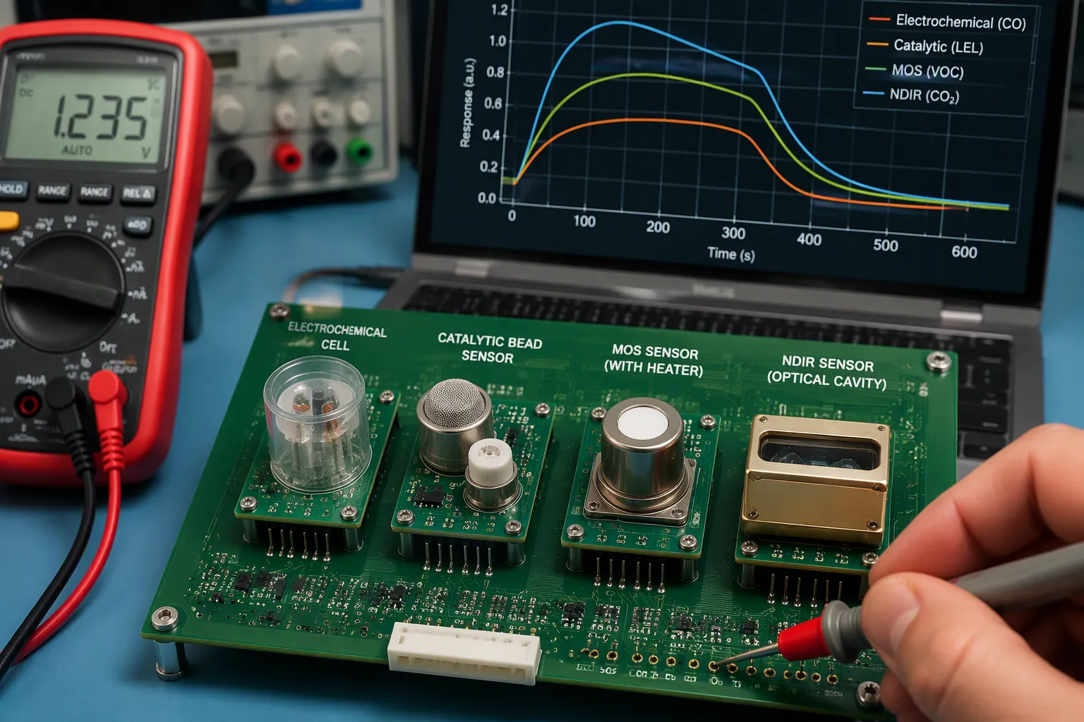
The sensor you pick shapes your board more than anything else. Each technology has its own output range, bias needs, warm-up time, and cross-sensitivity profile. First match the sensor to the target gas, then design the conditioning and enclosure around it.
Electrochemical, Catalytic, and MOS Sensors
Electrochemical cells work well for toxic gases like carbon monoxide and hydrogen sulfide. They put out small currents, need a steady bias, and take a long warm-up before the baseline settles. Catalytic bead sensors measure combustible gases as a percentage of LEL. They run hot, use more power, and need a reference bead for temperature compensation. MOS sensors are cheap and sensitive, but they drift and react to many gases at once. NDIR sensors count molecules through infrared absorption and avoid chemical consumption entirely.
科技 | 輸出 | Bias needed | 熱身 | 交叉敏感性 |
|---|---|---|---|---|
電化學 | pA–µA current | 可以 | 时间 | 中度 |
催化珠 | 阻力變化 | 沒有 | 分鐘 | Responds to most combustibles |
馬鞍山 | 阻力變化 | Heater supply | 分鐘 | 高 |
NDIR | Optical intensity | 沒有 | 強化- | 低 |
Cross-sensitivity is the main risk in any multi-gas sensor system. A gas other than the target can drive the electrode and cause a false reading. Standard industrial CO sensors react to hydrogen: 100 ppm of H2 can cause a false CO reading of 40 ppm. In battery-charging areas, hydrogen levels reach several hundred ppm and can set off false alarms when no carbon monoxide is present.
Cross-sensitivity occurs when a gas other than the gas being monitored can affect the reading given by an electrochemical sensor, causing the electrode to react even if the target gas is not present, or producing an inaccurate reading and/or alarm.
The numbers show how far this reaches. A CO sensor shows a 20% response to H2 and a 1% response to H2S. An H2S sensor shows a 5% response to CO, a 20% response to H2, and a 300% response to HCl. Pick sensors with low cross-response for the mixture you expect, and add filtering in firmware.
Mid-Infrared Multi-Gas Sensor System Design
A mid-infrared multi-gas sensor system uses the strong absorption of small molecules in the mid-IR fingerprint region. Mid-infrared absorption spectroscopy gives much stronger lines than near-IR overtone bands, so you can detect gases down to ppm–ppb levels. Pairing narrow-linewidth mid-IR sources with multi-pass cells gives selectivity below 10 ppb even in complex matrices. This approach supports CO, CO2 and CH4 sensing on one optical bench.
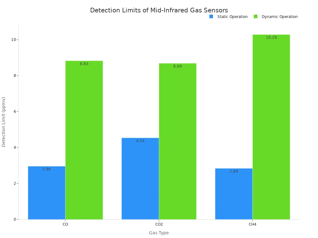
Detection limits for CO, CO2 and CH4 detectors depend on the operating mode. Static operation reaches 2.96 ppmv for CO, 4.54 ppmv for CO2, and 2.84 ppmv for CH4. Dynamic operation relaxes these to 8.83, 8.69, and 10.29 ppmv. A scanning design finishes CO, CO2 and CH4 detection in 10 s, at 2 s per gas. Board-level NDIR designs draw about 30 mW and respond in roughly 10 to 14 s, far below the 350 to 400 mW of older MEMS and dual-channel units. That low power makes continuous multi-gas detection practical on battery-powered boards.
Integration still limits you. Keep sensor sockets away from heat sources and seal them against dust. Ventilation paths must let gas reach every cell without letting water in. Route the optical cavity of a multi-gas sensor clear of flexing or vibration.
Signal Processing in Multi-Gas Detection Systems

A raw sensor voltage means nothing until firmware turns it into a concentration. You convert each channel with a 校準曲線, then correct for temperature and humidity, then compare the result against alarm limits. This stage decides whether your multi-gas sensor tells the truth.
Calibration and Cross-Sensitivity Compensation
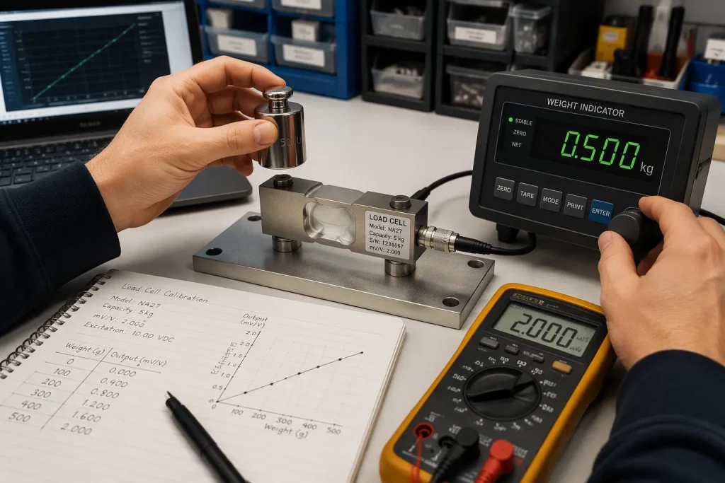
Start with a zero calibration in clean air to set the baseline. Then attach the calibration cap and apply span gas at the manufacturer’s flow rate (usually 0.5–1.0 L/min). Adjust the reading to the known concentration. Span gas usually sits at 25–50% of full scale. Write down every event: date, detector ID, gas type and lot number, zero and span readings, pass/fail, technician, and next due date. Bump tests belong before each day’s use, with full calibration at least every 12 months. Keep records traceable to OSHA 29 CFR 1910.146 and the EPA Traceability Protocol.
溫濕度 shift every sensor’s output. Build a compensation model that takes the raw signal plus a temperature reading and returns a corrected value. A lookup table with interpolated points works well, and a fitted polynomial suits smoother curves. Generic curves are not enough — temperature dependence varies by model, target gas, batch, and aging.
方面 | 電化學傳感器 | MOS感測器 |
|---|---|---|
溫度效應 | Reaction rate shifts; a galvanic O2 cell drifts about 10% from +20°C to -20°C, an H2 sensor about 80% | Drift often exceeds ±30%, making tight accuracy at extremes nearly impossible |
補償方式 | Quadratic or cubic equation on normalized temperature coefficient | Quadratic equation or lookup table, ideally per unit |
局限性 | 一般有效 | Unit-to-unit spread defeats a unified formula |
Treat humidity separately. It affects electrolyte water balance and condensation, not reaction kinetics. A multidimensional model using raw signal, temperature, and humidity handles the interaction best.
Alarm Thresholds and Output Drive
Set thresholds from the hazard, not from sensor convenience. For combustibles, act at 20% LEL as a factory default low alarm and 50% LEL as the high setting, keeping a wide margin before ignition. Oxygen alarms at 19.5% and 23.5% by volume. Carbon monoxide alarms at 35 ppm low and 70 ppm high, with a 35 ppm TWA and 200 ppm STEL. Hydrogen sulfide alarms at 10 ppm low and 20 ppm high, with a 10 ppm TWA and 15 ppm STEL.
Add hysteresis to every threshold so a reading hovering at the limit does not chatter the buzzer. Latch critical alarms until an operator acknowledges them. Drive the buzzer through a transistor with a flyback diode, and drive relays the same way. Check coil current against the driver’s rating before you commit the board.
Multi-Gas Monitoring Design Considerations
Power, Compliance, and DFM Constraints
Battery-powered designs succeed or fail based on the sampling schedule. Average power follows duty cycle almost directly. A ceramic Figaro TGS 26XX run at 0.8% duty in 10-minute cycles draws very little average current. The catch is the active phase. It must be longer than the heater thermal time constant, about 3 s for ceramic parts, so a 5 s active window works. MEMS parts such as the MiCS-5525 handle 20–60% duty cycles with 0.5–1.5 s periods, and 30% at 0.5 s is a good starting point. If you push the period from 0.5 s to 1.5 s, the detection limit goes up.
Duty cycle / period | 感應器類型 | 電源效應 | Response-time effect |
|---|---|---|---|
0.8% in 10-min cycles (~5 s active) | Ceramic TGS 26XX | Very low average power | Active phase must exceed ~3 s thermal time constant |
20–60%, 0.5–1.5 s periods (30% at 0.5 s optimal) | MEMS MiCS-5525 | Higher duty, higher average power | Longer period raised detection limit |
10% in 10-min periods | MOX (CO prediction) | Saved up to 90% energy | Error rose to a factor of 2 |
計畫中 | MOX (CO prediction) | 最低能量 | Error increased about 5× |
For battery-powered products, “low power” should be judged by the whole operating profile—not just by one heater number. Duty cycle, warm-up strategy and sampling interval all matter.
Compliance also shapes the board. EN 50291:2010 covers electrical apparatus for detecting carbon monoxide in domestic premises. UL 2034 covers single and multiple station carbon monoxide alarms. Listed units must meet response-time requirements at various CO levels and avoid nuisance alarms from non-CO vapors. Design your gas detection firmware and filter stages against these limits early, not after layout.
Reliability and System Integration
Ventilation decides whether your multi-gas sensor sees the gas at all. Line up enclosure openings directly with sensor positions, face each sensing port toward the holes, and keep clearance around every cell. Blocked airflow cuts responsiveness and accuracy. Place humidity sensors in the lower third of the enclosure, because moist air settles near the bottom and top-mounted parts can read 10–15% RH low. Keep them away from heaters and near cable entries, where moisture gets in first.
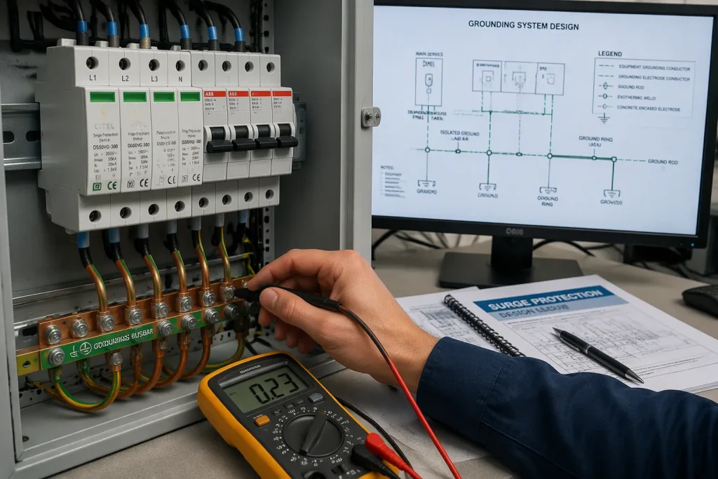
Route analog sensor cables away from power conductors and use shielded, grounded runs to limit EMI pickup. Add redundant sensors at critical points so one failure leaves no blind spot. Match response expectations to the application: temperature sensors at 1–5 s track thermal mass, while humidity sensors should respond within about 30 s. A multi-gas detector built this way supports continuous gas safety monitoring without surprises in the field.
Your multi-gas sensing platform follows one path: sensors convert gas into current, conditioning turns that current into a clean voltage, the MCU computes concentration, and the alarm stage acts on the result. Sensor selection, calibration strategy, alarm logic, and board-level manufacturing choices together decide real-world safety performance. Temperature and humidity drift can push readings off baseline, so compensate for them and you cut nuisance alarms in multi-gas detection. Treat the multi-gas sensor as a safety layer, not a measurement accessory. Validate every gas detection design against the relevant standards and your application requirements. A well-built multi-gas fixed safety system earns trust through repeatable calibration and honest alarm behavior.
常見問題
How long should you warm up a sensor before calibration?
Wait until the baseline is steady. Biased electrochemical cells usually need about 6 hours or more after installation. Keep the bias applied when the board is powered off. If you don’t, the warm-up cycle starts over before every use.
Which gases belong in a standard four-gas configuration?
Use oxygen, combustibles (LEL), hydrogen sulfide, and carbon monoxide. This set covers both toxic and flammable hazards. A single-channel unit would miss most of them. Match each channel to the sensor technology that fits its output range and bias needs.
How often should you calibrate a multi-gas detector?
Run a bump test before each day’s use. Do a full calibration at least every 12 months. Apply span gas at the manufacturer’s flow rate, usually 0.5–1.0 L/min, and set the span point at 25–50% of full scale. Write down every event with details you can trace.
What causes false alarms in gas detection?
Cross-sensitivity causes most of them. A carbon monoxide cell can respond to hydrogen, and an H₂S cell can react to other vapors. Add hysteresis and latching to your alarm logic. Then make up for temperature and humidity drift before you compare readings against thresholds.
Why does sampling duty cycle matter for a multi gas monitor?
Average power follows duty cycle almost directly. A short active window saves energy, but it must be longer than the heater’s thermal time constant. If you make the sampling period too long, the detection limit goes up. Balance power budget against response time for your application.