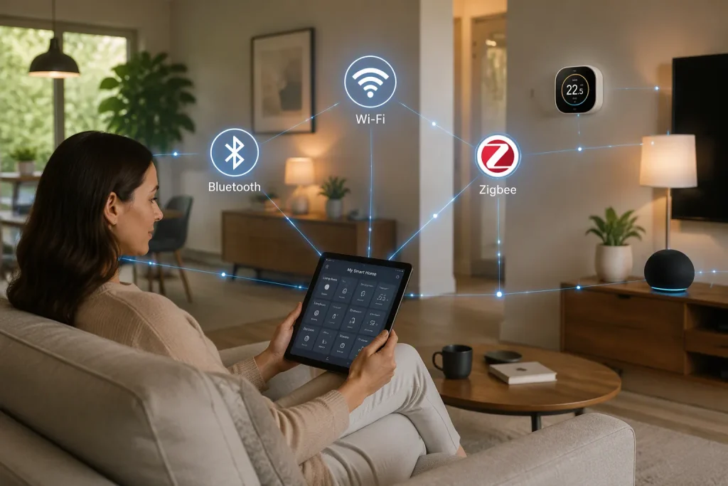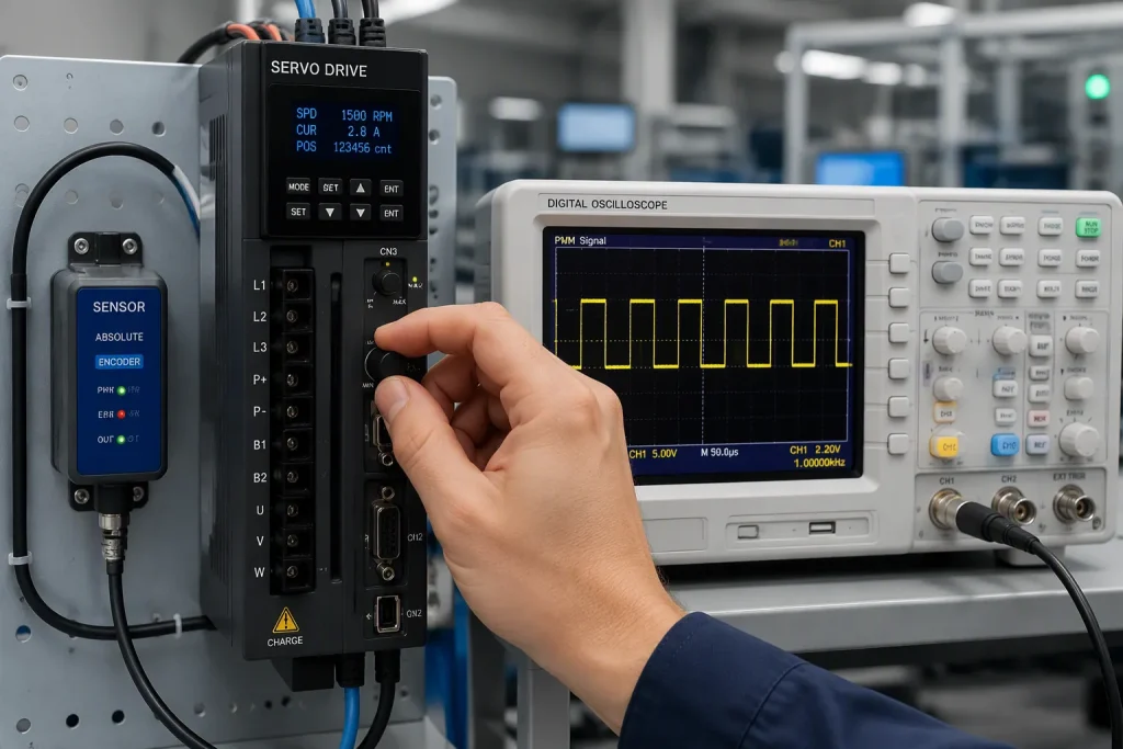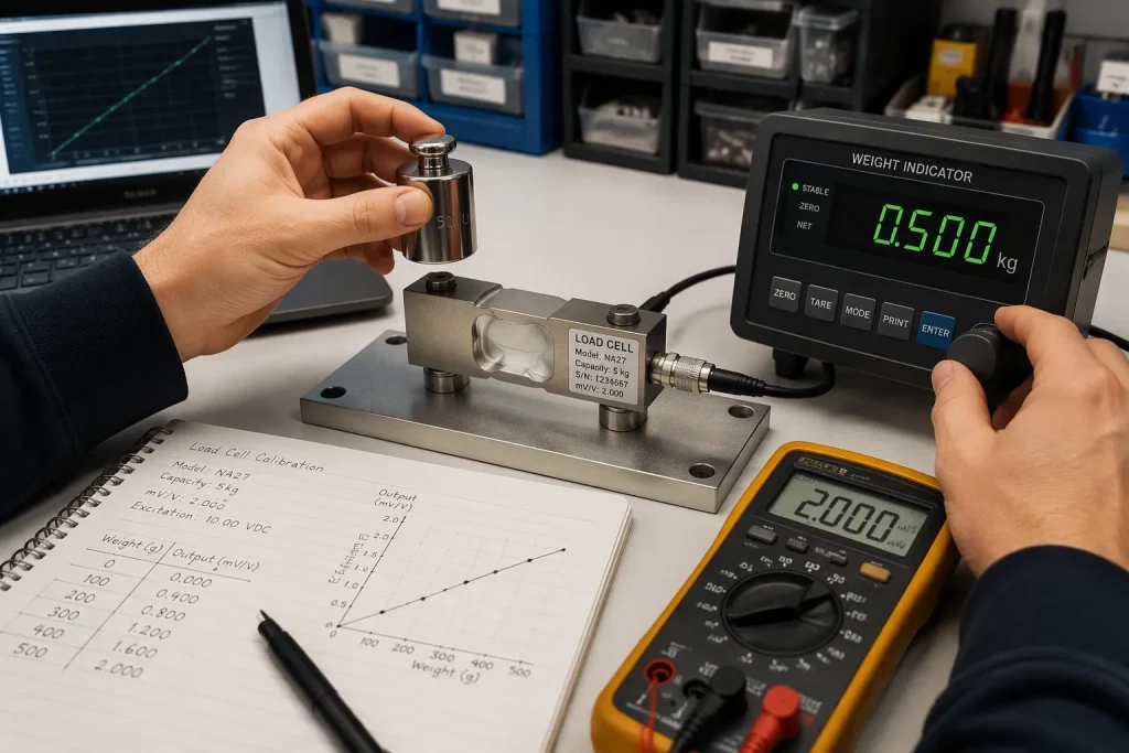
Water systems need electronics that can handle humidity, chemicals, and electrical noise. A board must measure chemical levels and run pumps and valves in these tough conditions. A well-designed board-level interface for water quality monitoring and pump valve control makes a closed-loop system possible. That system protects water supplies by responding in real time.
This guide focuses on practical hardware design and manufacturing for electronics teams. It does not cover utility-level operations. Putting sensing front ends, actuator drivers, and control logic on one PCB is the foundation. This setup supports steady, ongoing measurement of water quality and automatic valve and pump response. Designers who treat the board as one coordinated system get stable readings and reliable actuation. The sections ahead look closely at sensing, actuation, control, and manufacturing trade-offs.
關鍵要點
Pair each water probe with its own signal chain to get steady readings.
Use solid-state relays for pump and valve control that switches on and off often.
Set up a local feedback loop so the system reacts quickly to changes in water quality.
使用 conformal coating and sealed enclosures to protect the boards.
Check the probes on a regular schedule so the data stays reliable.
System Context for Hardware Design
Sensors, Actuators, and Control
Every water system depends on three parts. Sensors collect information about the water. Actuators, which are pumps and valves, respond to that information. A control unit ties the two together. The board sits at the middle of this loop, and it must read a probe and switch a load with the same confidence.
Water quality monitoring panels check chlorine, turbidity, pH, conductivity, pressure, and temperature. Each reading connects to its own board-level interface. Electrochemical probes need high-impedance analog front ends. Turbidity sensors often send an optical signal that needs gain and filtering. Pressure and temperature transducers usually provide a bridge or a digital bus. Designers should treat each channel as its own signal chain instead of pushing every probe through one generic input stage.
SCADA系統的作用
SCADA systems automate processes and give operators a clear view. The name stands for supervisory control and data acquisition, and the setup splits cleanly into layers. Field devices handle measurement and actuation. PLCs run the local logic. SCADA systems collect data, raise alarms, and log trends. The PCB is the link between the field and that upper layer.
SCADA systems for water treatment seldom connect to raw sensors directly. They count on the board to condition signals, isolate grounds, and present clean values over Modbus, 4-20 mA, or digital I/O. Water treatment SCADA systems also need reliable alarm paths, so scada alarm management water plants trust begins with hardware that reports faults honestly. SCADA control systems for pump stations carry the same requirement.
Monitoring does not end at the treatment plant. Water and wastewater treatment plants increasingly place distributed nodes across a network. PLC and SCADA water systems in these designs must handle long cable runs and links that drop out. Remote nodes therefore need sturdy, low-power board designs. Careful monitoring of supply current and sleep behavior keeps battery-powered units alive for years. The same care applies to water treatment plants of every size.
Water Quality Monitoring Front Ends
Probe Interfaces and Signal Conditioning
Every probe type has its own electrical traits, so the front end has to match each one. The table below sums up common interface choices for the five main parameters.
探測器 | Typical Interface Options | 筆記 |
|---|---|---|
pH | RS485/Modbus (IP68 field units); industrial analog; Gravity | RS485 works well for outdoor multi-parameter systems; analog works for continuous monitoring; Gravity works for prototyping |
氧化還原電位 | Industrial analog; IP68 RS485/Modbus | RS485 supports continuous field monitoring |
電導率(EC) | RS485 (K=1, K=10); lab-grade analog; industrial analog | K=1 for general water; K=10 for high-conductivity liquids such as wastewater and concentrates |
溶解氧 | RS485 (fluorescence-based) | Freshwater and seawater versions exist |
濁 | RS485 (industrial) | Works with pH, EC, and DO in distributed stations |
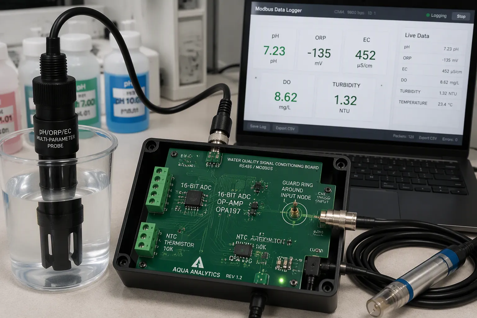
RS485/Modbus is the best choice for long cable runs and spread-out setups. Analog paths still make sense when a designer needs tight control over filtering and gain. A 16-bit ADC or better keeps resolution after amplification. Temperature compensation belongs on the same board, because pH, conductivity, and DO readings all shift with temperature. Designers should pair each analog channel with an NTC thermistor or digital temperature sensor and apply real-time correction.
High-Impedance Design and Isolation
The pH and ORP electrodes act like weak current sources. Their output impedance is far higher than ordinary op-amps can handle. Front-end design therefore starts with choosing the op-amp. JFET or CMOS input types with femtoampere-level input bias current keep the sensor current from leaking into the amplifier.
Guarding turns that idea into a layout rule. A guard ring surrounds every high-impedance node and connects to a low-impedance point at the same potential, usually the op-amp output. The guard soaks up leakage from nearby traces. Keep the guard within 1 mV of the guarded node to hold leakage below 1 pA with 1000-MΩ leakage resistance. Modern low-offset op-amps meet that window. Place guards on both PCB sides for through-hole parts and stitch them with several vias. Design guards in from the start, since they cannot be added later.
Several supporting practices complete the front end:
Pick laminates with CTI above 400 V, and favor low-moisture materials such as polyimide, PTFE, or high-grade FR4.
Apply conformal coating in epoxy, silicone, or parylene to boost surface insulation.
Use star grounding to keep analog ground apart from digital and power ground.
Add shielded enclosures over sensitive analog areas.
Provide test points for insulation resistance and surface insulation resistance checks.
Galvanic isolation breaks ground loops between probes and the control board. It also shields sensitive electronics from fault currents in wet places. Digital isolators or isolation amplifiers on each probe channel stop a single ground fault from spoiling every reading.
Electrochemical sensors need conditioning before they give trustworthy data. pH and ORP electrodes need a polarization period after power-up, and the firmware should ignore readings until the electrode settles. Dissolved oxygen probes based on fluorescence need a warm-up cycle too.
Remote nodes cannot afford to sample at full power all the time. A duty-cycled schedule wakes the ADC, takes a burst of readings, and goes back to sleep. This approach supports continuous measurement of water quality over long deployments while keeping average current low. Careful monitoring of sleep current and sensor warm-up time decides battery life. Teams that tune both get accurate and continuous monitoring across seasons.
Driving Pumps and Solenoid Valves
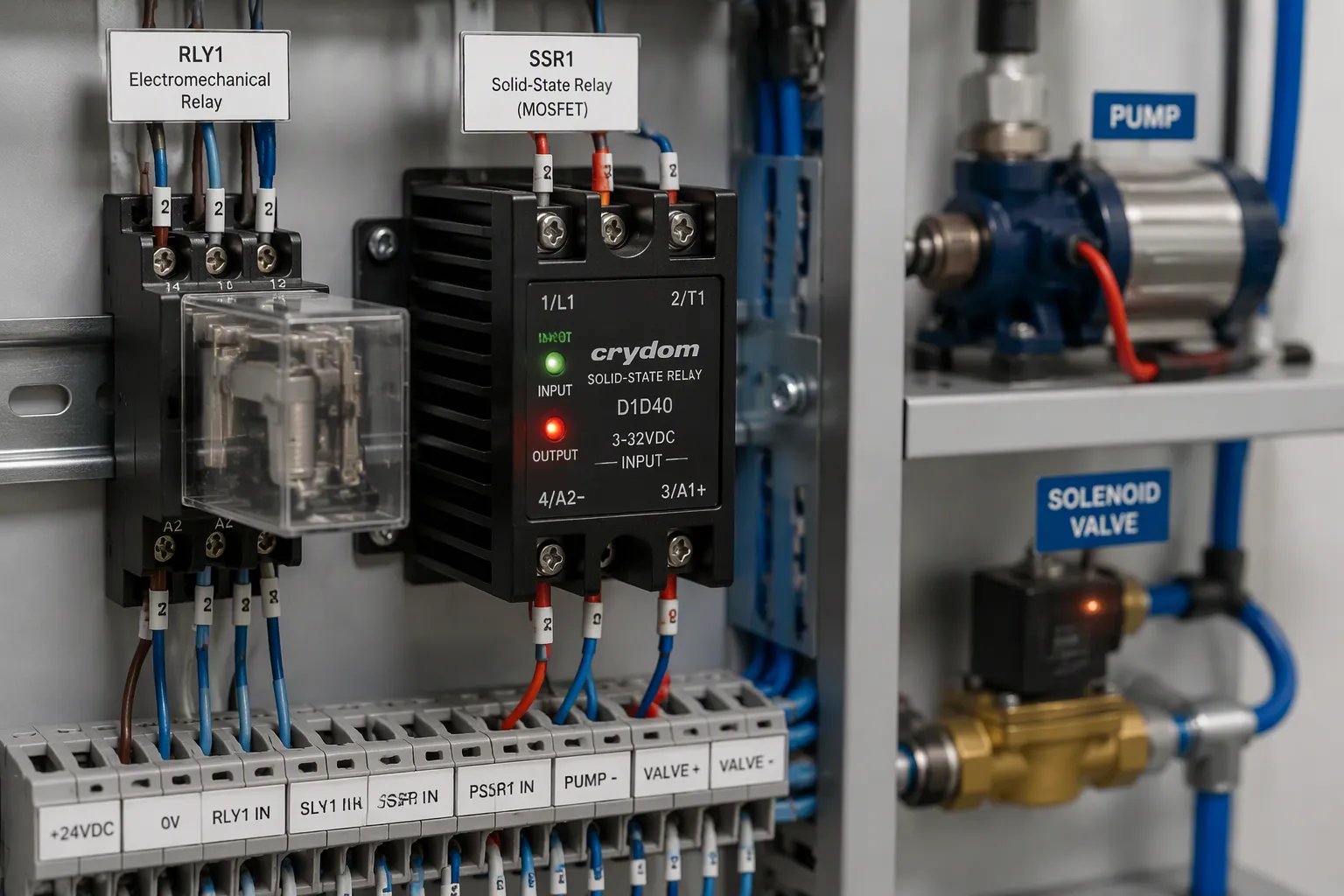
Relay vs. MOSFET Actuation
The actuator driver decides how long a board lasts in the field. Electromechanical relays cost less per unit and work well for simple, low-frequency switching. Their contacts wear down from arcing and erosion, and humidity, dust, and corrosion break them down over time. Solid-state relays built on MOSFETs have no moving parts. They switch silently, run faster, and stand up to vibration, dust, and humidity much better.
MOSFET-based SSR designs include built-in overcurrent and thermal protection circuits that respond to faults on their own, greatly extending operating life compared to traditional electromechanical relays. Test methods include surge immunity testing up to 8kV and vibration resistance testing at 10–2000 Hz, with documented lifespans over 100 million operations—consistently showing about 10x longer operating life than mechanical alternatives.
屬性
電磁繼電器
Solid-State Relays (MOSFET-based)
Average lifespan (operations)
~100,000 electrical / ~1,000,000 mechanical
100,000,000+
Reliability rating
Lower due to mechanical wear
Higher due to no moving parts
Noise / vibration / EMI
Audible noise; susceptible to wear; can emit EMI from coils/sparks
Silent; superior vibration reliability; minimal EMI
預付費
較低的購買價格
較高的初始成本
Harsh-environment suitability
Robust but contacts degrade with humidity, dust, corrosion
Better resistance to vibration, dust, and humidity
SSRs make more heat and often need heat sinks, which makes small enclosures harder to build. A designer comparing pump drivers should match the choice to the duty cycle. High-cycle, low-maintenance deployments justify the higher upfront cost of an SSR. Budget-limited, low-use projects are still the best fit for a mechanical relay.
EMI and Transient Suppression
Inductive loads store energy in a magnetic field. When a switch opens, the collapsing field sends a reverse-polarity spike toward the driver. A flyback diode across the coil gives that current a low-resistance path. The diode clamps the coil voltage to its forward drop, and the stored energy fades away as heat in the winding. Place the diode right across the coil, reverse-biased to the supply, as close to the inductor as you can. Schottky and fast-recovery types work for low-voltage or fast-switching cases.
Flyback protection alone does not block all interference. Motors and solenoids send noise through the air and through wires into logic and supply rails. Practical countermeasures include:
Single-point, multi-point, or hybrid grounding chosen by operating frequency.
Metal barriers to block radiated coupling.
Filtering on power, signal, and control lines.
A ceramic capacitor of 100 pF to 100 nF across motor terminals, placed close to the motor.
Surge suppressors at the source for loads switched by hard contacts.
Liquid level sensing closes the actuation loop. Float switches, capacitive probes, and pressure transducers feed the same 控制邏輯 that drives the pump. The firmware should debounce level inputs and enforce a minimum off-time between starts, which limits inrush current and protects pump operations.
Control Integration and Communication
Closed-Loop Feedback on the Board
A local feedback loop turns readings into action without waiting for a remote host. The control logic checks each sensor value against a set limit. If a pH reading falls outside its range, it triggers a dose from the chemical feed systems. A falling level input starts a pump. The board runs this loop in firmware, so response time follows the sampling cycle, not the network.
Conductivity and salinity readings need their own trip points. When conductivity passes a set limit, the board raises an alarm or closes a valve to isolate the affected section. Operators then catch water quality concerns early, and water quality monitoring continues through the event. The same logic supports chemical feed control, where dosing follows measured demand.
Interfacing with SCADA Systems
The board reports upward to SCADA系統 and accepts commands from them. Standard interfaces cover most sites.
協定/介面 | 項目類別 |
|---|---|
0/4–20 mA analog output | Analog current loop |
EtherNet / IP的 | 工業以太網 |
MODBUS | Serial/fieldbus protocol |
PROFIBUS | 現場總線 |
工業以太網 | 工業以太網 |
Two independent 4-20 mA outputs allow proportional control of metering pumps or motorized valves. Modbus RTU and Modbus over Ethernet link HMIs and loop hardware. ASCII serial and Profibus appear on data logging modules. These options let a panel join almost any scada systems for water treatment.
場 上市公司 run local logic, and scada systems collect trends above them. In plc and scada water systems, the board bridges probe wiring and that hierarchy. Water treatment plants depend on the same stack, and scada alarm management water plants trust starts with honest fault reporting. Operators set starts, stops, and setpoints centrally, while equipment control stays local. Process monitoring, real-time monitoring, and continuous monitoring of water quality conditions all rest on clean data. Scada control systems for pump stations need fast valve response and segmented networks. Plcs handle interlocks, and scada systems log events on one shared time base. A second look at plc and scada water systems shows the same pattern: scada systems push updates, and the platform keeps the audit trail.
Manufacturing and Reliability
Corrosion Protection and Enclosures
Humidity, salt fog, and chemical spray start attacking a board on day one in the field. Conformal coating protects the PCB itself, and a sealed enclosure protects the whole device. Designers should use both when conditions are harsh. The coating choice depends on the chemistry of the site.
塗層類型 | Moisture/Corrosion Protection | 關鍵力量 | 常見的權衡取捨 | 最適合 |
|---|---|---|---|---|
Acrylic(壓克力) | 中度 | 易於應用和返工 | 較低的耐化學性 | 通用防護 |
矽膠 | 固德 | Flexible and handles temperature | Can pool on complex shapes | 高溫組件 |
聚氨酯 | 固德 | Resists chemicals and abrasion | 難以修改 | 化學腐蝕環境 |
環氧 | 高 | Durable and resists chemicals | Rigid and hard to remove | 高壓力環境 |
聚對二甲苯 | 優 | Ultra-thin, pinhole-free coverage | Needs vapor deposition | Miniaturized, high-reliability electronics |
Enclosure ratings set the second layer of defense. An IP66 housing keeps out dust and strong water jets. An IP67 unit survives being briefly underwater up to 1 meter. An IP68 unit works for long-term immersion in deeper water. Sealed connectors must match the housing rating, or water gets in through the cable entry.
DFM Constraints and Trade-Offs
A mixed-signal board carries very high impedance analog traces next to high-current actuator drivers. Fabricators need plenty of isolation spacing between those zones. Creepage and clearance rules get bigger when the driver switches a pump at mains voltage. Thermal relief for the drivers also uses copper area that the analog section would otherwise need.
Testability gets harder when the two domains share one substrate. Probe front ends need guarded test points and a way to check insulation resistance after coating. Drivers need current probes and thermal coupons. Teams should save test pads before layout freeze, because coating and potting hide them later.
Deployed boards need a steady calibration and reliability routine. Routine multiparameter probe calibration should happen at least once every two weeks with traceable standard solutions. Recalibration runs every two months under quality assurance protocols. Event-triggered checks follow extreme weather, severe biofouling, or drift in the data stream. Preventive maintenance covers sensor cleaning, membrane and electrolyte replacement, and connector inspection. Standardized protocols for warm-up time, stabilization checks, and calibration logs keep monitoring data traceable across the fleet.
Three board-level pillars support every water system design. Strong sensing front ends keep pH, ORP, conductivity, and turbidity readings steady. Reliable actuator drivers switch pumps and valves without fail. Smooth control integration links sensing and actuation into one loop. Teams that treat these pillars as one system get dependable results.
Protecting water supplies starts with well-engineered PCBs. A strong board allows continuous water quality monitoring and fast pump and valve response. It also sends clean data to scada systems and keeps local control quick.
Hardware teams must balance performance, reliability, and DFM 限制. Careful layout, isolation, and coating choices make the next generation of water quality and monitoring electronics possible.
常見問題
How does a board keep pH and ORP readings stable over long deployments?
A designer should begin with a JFET or CMOS op-amp that has femtoampere-level input bias current. A guard ring must go around every high-impedance node and stay within 1 mV of that node. Conformal coating and star grounding then help hold leakage down. The firmware should also skip readings until the electrode finishes polarizing after power-up.
When should a team choose a MOSFET solid-state relay over a mechanical relay?
A team should choose the solid-state relay for high-cycle, low-maintenance sites. These parts list lifespans above 100,000,000 operations, about ten times the mechanical option. A mechanical relay still works for budget-limited, low-use projects. Either way, a flyback diode belongs right across the coil to clamp the inductive spike.
Which interfaces connect a monitoring board to scada systems?
Most sites depend on 4-20 mA analog outputs, Modbus RTU, or Modbus over Ethernet. Two independent 4-20 mA outputs allow proportional control of metering pumps and motorized valves. These choices let a panel join almost any scada systems for water treatment. Local plcs keep interlocks fast, and scada systems log events above them.
What maintenance keeps deployed boards trustworthy?
Teams should calibrate multiparameter probes at least once every two weeks with traceable standard solutions. Recalibration runs every two months under quality assurance protocols. Event-triggered checks follow extreme weather or data drift. Preventive work covers sensor cleaning, membrane replacement, and connector inspection. Standardized warm-up and stabilization logs keep data traceable across the fleet.