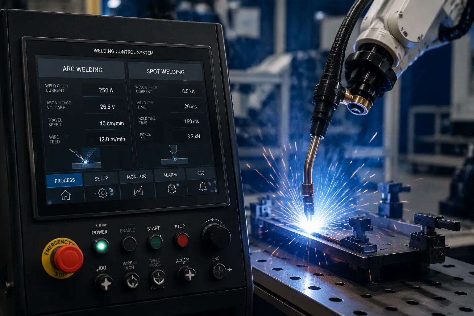
An arc welding and spot welding control system is the set of electronics and software that controls welding settings. This keeps each weld consistent, safe, and repeatable. The two processes work on different physics, so their control systems manage different variables. An arc welding controller manages arc stability, current, and voltage. A spot welding controller manages current, time, and electrode pressure. Hardware engineers and electronics product teams face real board-level choices here. Power stage selection, isolated gate drive, current measurement, and high-voltage spacing all shape the final design. Manufacturing trade-offs come right after. Designers must weigh thermal cycling, creepage and clearance, and DFM limits before a control system reaches production.
關鍵要點
Arc welding control systems handle arc steadiness, current, and voltage to keep welds consistent.
Spot welding control systems control the current, time, and electrode pressure to make strong, repeatable welds.
Closed-loop feedback makes welds better by adjusting for electrode wear and changes on the surface.
Design choices at the board level, like heat control and high-voltage spacing, affect how reliable a welding system is.
Knowing how welding works helps engineers pick the right control system for each job.
Arc Welding Control System Basics
The arc welding control system is the enclosure and the circuit boards inside it. These parts control weld current, voltage, wire feed, arc distance, and travel speed. Computer-controlled arc welding stations keep these functions in sync. The AWS-210-400-800 family, for example, uses microprocessor-based programmable power supplies. These units give closed-loop servo control of weld current, travel speed, arc distance, and wire feed. Current, voltage, travel, and wire feed stay in sync within the system.
關鍵部件和功能
The design splits into functional areas. The table below sums up the division of labor.
控制組件 | Assigned Functions |
|---|---|
Controller domain | Handles parts and functions closely tied to the welding process itself |
Supervisor domain | Handles more general functions (higher-level oversight) |
Multivariable controller | Replaces the first estimate of indirect welding parameters once welding has started (t > 0) |
操作員輸入 | Sets only direct weld parameters such as weld width and penetration depth |
The welding machine’s controller therefore separates process-level control from higher-level oversight. The operator sets direct welding parameters. The multivariable controller improves the estimate of indirect parameters after the arc starts.
逐步操作
A typical cycle goes through several stages. The operator enters direct parameters at the interface. The supervisor domain passes these targets to the process-level controller. The power stage then powers up the arc. The multivariable controller updates its estimate of indirect parameters once welding begins. Closed-loop feedback keeps current, voltage, travel, and wire feed on target. The system shuts the arc down at the end of the pass.
設計注意事項
Board-level choices drive performance. For the power stage, you should weigh IGBT, MOSFET, and SCR options against switching frequency and conduction loss. Isolated gate drive with enough dead-time prevents shoot-through. Snubbers, TVS diodes, and varistors clamp switching transients and line surges. Current measurement relies on a shunt, a Hall sensor, or a current transformer. Each method trades accuracy against isolation and cost. Opto-isolation separates the power stage from control logic. Creepage and clearance must meet high-voltage spacing rules. Heavy copper and busbars carry the very high current path. Heatsinking and thermal cycling limit device life. DFM constraints shape layer count, copper weight, and assembly flow. These trade-offs decide which design reaches production.
Spot Welding and Resistance Spot Welding Systems
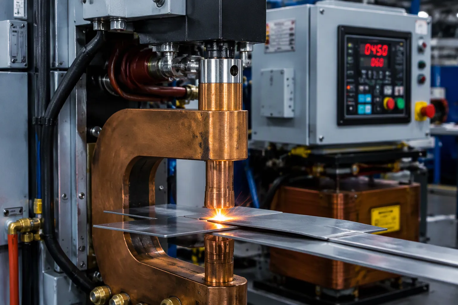
A spot welding system joins metal sheets at one point. It uses pressure and sends electric current through the stack. Heat from electrical resistance melts the base metal at the faying surface. Engineers call this resistance spot welding, one of several types of resistance welding. Production lines often run MFDC-RSW (medium-frequency direct current) equipment or PLC-controlled automation. In networked cells, an AW controller board talks to a 785 integrated weld control timer board over a serial link. The timer board owns the firing schedule. The AW board handles sequencing and handshakes.
Spot Welding System Components
The parts of a spot welding system fall into mechanical, electrical, and control groups. The table below shows each component and its job.
元件 | 功能 |
|---|---|
工具架 | Hold the electrodes firmly and support optional water hoses that cool them |
電極 | Low-resistance copper alloy, shaped per application; form part of the transformer secondary circuit |
電源 | Provides electrical power to the welder |
Energy storage unit | Capacitor bank delivers high instantaneous power; not needed when demand is low |
軸體 | Dumps stored energy into the welding transformer |
焊接變壓器 | Steps voltage down and current up, reducing the level the switch must handle |
控制箱 | Manages the switch and may monitor electrode voltage or current |
C-type gun | High rigidity and tooling flexibility with collinear motion; suits high-force work on thick material |
X-type gun | Larger workspace but less rigidity; suits thin flat panels and needs dome-shaped tips |
How to Spot Weld: Control Sequence
Operators follow a fixed sequence. The control box times each stage.
Squeeze time — electrodes close and build force before current flows, seating the sheets and stabilizing contact.
Weld time — current passes through the stack, and electrical resistance heating grows the nugget.
Hold time — current stops but force continues; the nugget solidifies under pressure.
Off time — electrodes retract and the workpiece advances, setting the cycle rate.
Weld time starts on its own after squeeze time. Hold time comes after heat time, and off time closes the loop. These welding parameters of spot welding — squeeze, weld, hold, off — set the spot welding parameters for a given joint. Closed-loop feedback measures welding current with a shunt resistor or a Hall sensor. This beats open-loop timing-only setups because it makes up for electrode wear and tab oxidation. A current transformer offers another isolated option. The control system adjusts firing to hold the target.
設計準則
Mains inrush and surge handling need early attention. A varistor plus TVS clamp protects the front end. Heatsinking must cover both power devices and electrodes, since thermal cycling wears tips and solder joints alike. Spot welding pressure settings interact with current and weld time, so check all three together. DFM constraints shape busbar layout and copper weight. Keep creepage and clearance generous on the high-voltage side. A sound resistance welding technique pairs short weld time with enough force. Every spot welding machine rewards careful board design. The spot welding process stays repeatable when the electronics hold their targets.
Comparing Control Systems and Design Trade-Offs
Arc vs. Spot: Key Differences
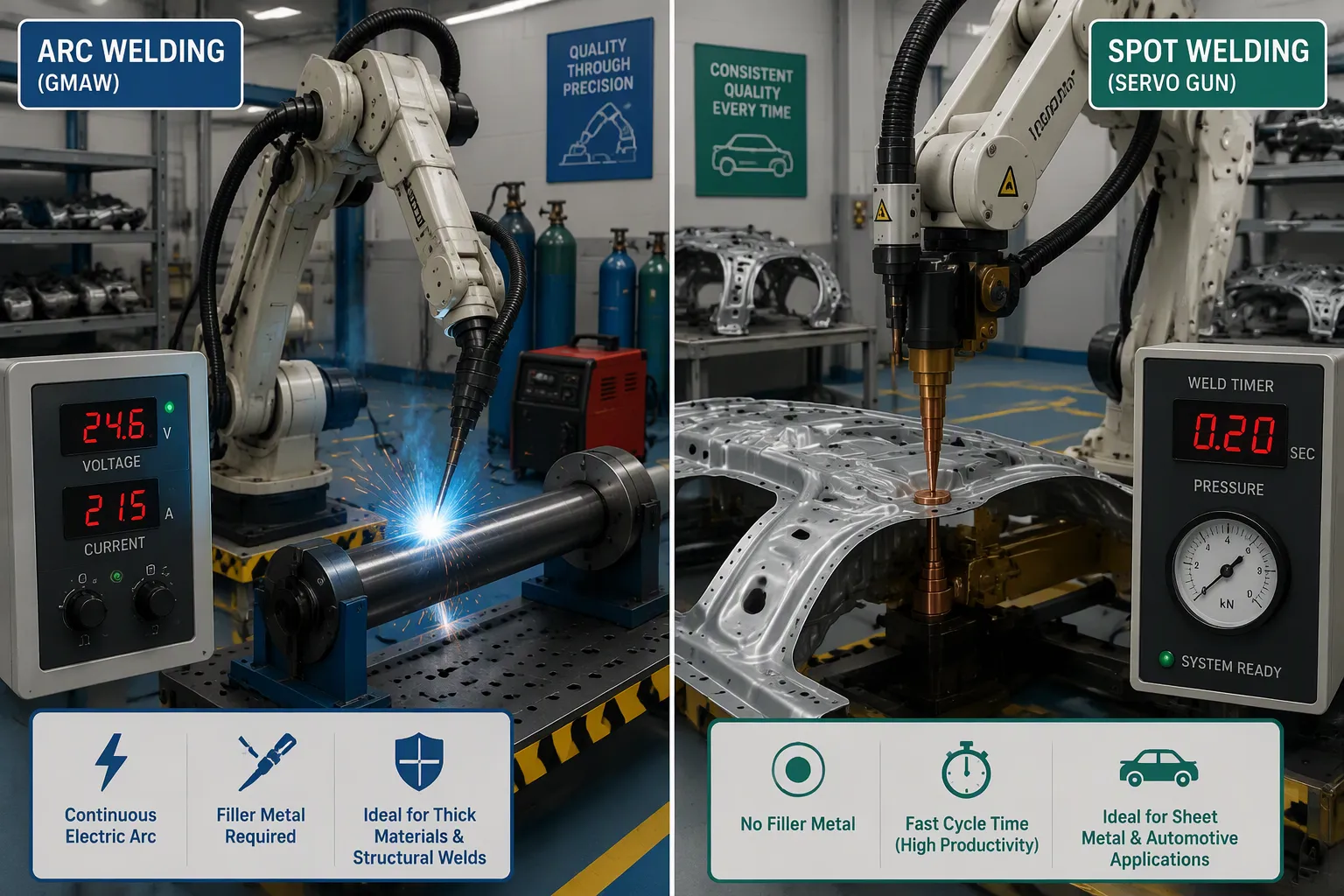
An arc welding control system manages arc stability, current, and voltage. A spot welding controller manages current, time, and electrode pressure. The arc process needs a steady plasma column, so the arc controller fixes voltage and current many times per second. The spot welding process depends on heat from electrical resistance at the faying surface. Here the controller times the electric current pulse and keeps spot welding pressure steady.
The welding parameters of spot welding — squeeze, weld, hold, and off — have no arc equivalent. Arc systems instead handle wire feed, travel speed, and arc distance. A spot welding machine fires one pulse per point. An arc system runs without stopping along a seam. These differences shape board design. Arc boards need fast current loops. Spot boards need exact weld time counters, and weld time and current must track together.
Applications and Manufacturing Trade-Offs
Automotive manufacturing uses both processes at high volume. Automotive manufacturing lines also mix types of resistance welding. The table below lists common uses of spot welding and arc welding on a vehicle.
焊接工藝 | Typical Automotive Application | 關鍵細節 |
|---|---|---|
Robotic TIG | Thin-wall tubing, visible finished welds | Handles 0.5mm–3mm wall thickness; paired with ABB IRB 1660ID robots and Miller Dynasty power sources for precision arc control |
電阻點焊 | Automotive body-in-white and sheet metal assemblies | FANUC R-2000iC robots with servo guns; 1,200–1,800 spots/hour; nugget pull-test pass rates above 99.7%; electrode force 300–800 lbs |
MIG/MAG(GMAW) | Steel and aluminum components, incl. exhaust manifold brackets | Workhorse process for 1.2mm–12mm steel; pulsed MIG reduces spatter; CMT for spatter-free aluminum; real Tier 1 exhaust manifold bracket cell: 340 parts/shift, 22-sec cycle, rejection down from 4.2% to 0.3% |
A typical car body holds several thousand spot welds. This volume works because spot welding is very fast and easy for robotic arms to do on an assembly line.
Resistance spot welding and arc welding are often used in high-production jobs like the automotive industry, where spot welding joins thin sheet metal frames together.
The advantages and disadvantages of spot welding come from this speed. It is fast and robot-friendly, but it joins only thin sheet stacks. Electrode wear also shifts welding current over time. Arc welding handles thicker sections and long seams. Manufacturing trade-offs include cost, thermal cycling, creepage and clearance, and DFM constraints. Resistance welding boards face heavy thermal cycling. Both resistance welding and arc welding need careful busbar and copper design.
A welding control system is the electronics and software that manage a welding process. The arc welding control system keeps arc stability, current, and voltage on target. The spot welding system instead controls welding current, weld time, and electrode pressure. Both designs give consistent, repeatable, and safe welds. The spot welding process depends on tight timing, while arc work depends on fast current loops. Board-level choices and manufacturing trade-offs decide which control system fits a given product. Engineers should weigh thermal cycling, creepage and clearance, and DFM limits before release. Careful welding parameters and sound electric current paths keep every weld repeatable.
常見問題
What does a welding control system actually regulate?
A welding control system controls the energy that reaches the joint. An arc system keeps arc stability, current, and voltage on target. A spot welding machine instead times the pulse and holds electrode force. Each controller fits the physics of its own process.
Why does spot welding need closed-loop current feedback?
Electrode wear and surface oxidation change the resistance path over time. Open-loop timing cannot see that drift. A closed-loop controller measures welding current and corrects the firing angle. The spot welding process then stays repeatable across thousands of cycles.
How do engineers choose between arc and spot systems for a product?
The joint geometry decides first. Thin sheet stacks work well with spot welding, and long seams on thicker sections work well with arc. Production volume matters too. A robotic cell running 1,200–1,800 spots per hour favors resistance welding, while low-volume fabrication favors arc equipment.
What board-level issues cause the most field failures?
Thermal cycling is at the top of the list. Power devices and electrode tips both wear out under repeated heat pulses. Poor creepage and clearance on the high-voltage side causes breakdowns as well. Designers should also clamp mains inrush early. Careful layout of the electric current path stops hot spots.