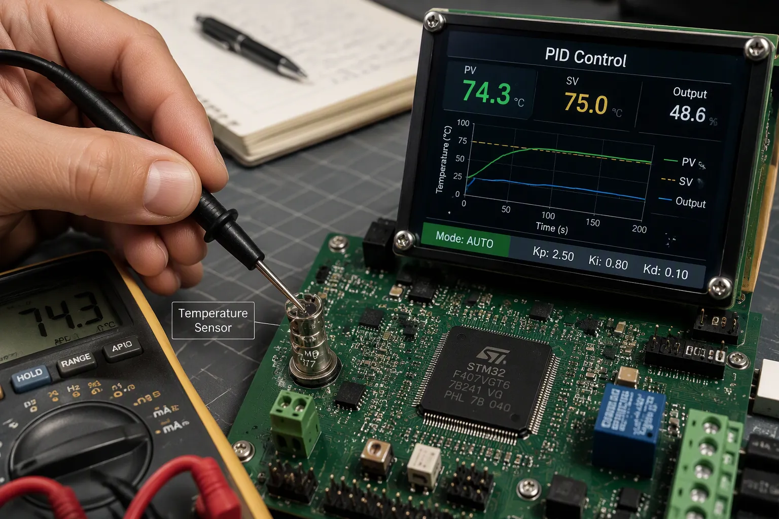
A PID controller keeps your board temperature within safe limits using closed-loop digital feedback. It compares the sensed board temperature to a setpoint, then adjusts the heater or cooler output. This is how pid temperature control protects a PCB from overheating.
Precise temperature control also prevents overshoot. Most overheat events start with overshoot, where the board briefly rises past the intended set-point before the loop reacts. A well-tuned PID responds early and keeps the board close to the target set-point.
You will learn the three PID terms, the sense-calculate-correct protection loop, board-level sensing and heater drive, and tuning with fail-safe design.
Основные выводы
A PID controller uses three parts to keep the board temperature steady and stop it from getting too hot.
Adjust the PID loop carefully so it does not overshoot and does not leave a steady-state error.
Add a separate hardware cutoff to protect against heater failures.
Pick the correct temperature sensor and put it away from hot spots.
Good thermal design and clean sensing help the PID loop work well.
PID Temperature Control Fundamentals
A PID temperature control system is a closed-loop digital feedback system. It checks the real temperature, figures out the gap from the setpoint, and fixes the output. That gap is the error. The controller uses this error to run a heater or cooler.
The Three PID Terms
The proportional, integral, and derivative terms each do a different job. The table below shows how a digital controller calculates each one.
Срок | Формула | How it is computed for temperature control |
|---|---|---|
Пропорциональный (П) | KP · e(t) | Uses the current error e(t) = SP − PV (setpoint minus measured temperature); a bigger error at that moment gives a bigger corrective output. |
Интеграл (I) | KI ∫₀ᵗ e(t) dt | Adds up the error over time (summed as ∑ eᵢ·Δt in discrete digital controllers) to remove steady-state offset in the temperature. |
Производная (D) | KD · de(t)/dt = −KD · d(PV)/dt | Reacts to how fast the error is changing; the error derivative is often swapped for the derivative of the measured PV to avoid derivative kick on setpoint changes, and filtering is used to cut down noise. |
The proportional term reacts to the current error. A bigger error gives a bigger output, so the доска heats faster. The proportional term alone cannot remove steady-state error, because the output drops to zero at the set-point. The integral term adds up past error and pushes that offset to zero. Too much integral action causes oscillation. The derivative term reacts to how fast things change. It predicts where the temperature is going and applies a braking effect. This damping cuts overshoot. The derivative term is sensitive to sensor noise, so many designs filter it or set it to zero.
Closed-Loop Feedback vs. On/Off Control
Simple thermostat on/off control turns the heater fully on below the set-point and fully off above it. The board temperature then cycles around the target. Each cycle carries the board past the target before the heater shuts off. That is overshoot, and it is where most overheat events begin.
PID controllers give more precise temperature control. The pid control algorithm adjusts output continuously instead of switching it. Proportional-integral-derivative controllers respond to small errors with small corrections. This behavior keeps the board close to the desired setpoint and limits overshoot. A well-tuned loop settles quickly with no steady-state error.
How PID Prevents Overheating
Sensing, Error Calculation, and Output
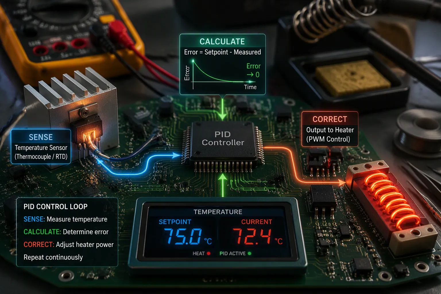
The protection loop runs in three steps. First, a sensor measures the board temperature. Second, the pid control algorithm subtracts that reading from the setpoint to get the error. Third, the output stage drives a heater or cooler by an amount the error justifies. This cycle repeats at a fixed sample rate, so the loop corrects small drifts before they grow.
The sense step carries the most risk. Common sensing methods include the thermocouple, the filled thermal well system, and the resistance temperature detector (RTD). Each one adds lag to the loop.
Зондирование метод | Role in the sense-calculate-correct loop |
|---|---|
термопара | Common temperature measurement device in the loop |
Filled thermal well system | Common temperature measurement device in the loop |
Resistance temperature detector (RTD) | Common temperature measurement device in the loop |
You should shrink measurement lag wherever you can. A small-diameter bulb or thermal well lowers the thermal resistance and thermal capacity of the element. A low-resistance, low-capacity well material cuts the lag it adds to the overall process. A small pipe or orifice near the sensor raises flow velocity and speeds heat transfer to the element. In two-phase systems, place the element in the liquid phase, which offers lower thermal resistance than the vapor phase.
Deadtime is a separate problem. It is the delay between a process variable changing and that change being observed. A sensor mounted far from a heat source will not register the shift at once. The controller then acts on stale measurements. Disturbances, such as a stray stream of cool air, also corrupt the reading. The pid control loop must reject them.
Overshoot and Thermal Runaway Prevention
Derivative action is the most noise-sensitive term. A noisy measurement signal makes derivative action amplify that noise, and the controller output turns jittery. Practical systems apply derivative filtering or use only a small D gain. A transmitter with derivative action can cancel some element lag; you compensate by reducing controller derivative gain.
Setpoint limits reduce overshoot further. Cap the output and clamp the allowed set-point range, and the loop cannot command a large correction that carries the board past target. Configured this way, the pid controller acts as an защита от перегрева, not just a regulator.
Thermal runaway needs its own layer. Watch for abnormal temperature rise and force the output off when it appears:
Junction temperature monitoring: embedded sensors, real-time diagnostics, and predictive monitoring detect abnormal conditions before failure.
Thermal shutdown protection: protective circuits for overcurrent, short-circuit, desaturation, and soft shutdown respond fast to faults and force output off before thermal escalation.
Voltage and impedance monitoring adds another check. A sudden voltage drop, imbalance, or rising internal impedance signals impending failure, and the system can isolate the module or shut down. Proportional-integral-derivative controllers handle the steady regulation; these detectors handle the fault. Together they keep precise temperature control intact and stop a fault from becoming a fire.
Board-Level Implementation for Precise Temperature Control
Sensing Options and Error Budget
Your first choice is the sensing element. An NTC thermistor costs little and comes in tiny SMD packages, so it works well for PCB ambient sensing. Its resistance curve is highly non-linear, and you need a lookup table or the Steinhart–Hart equation to convert readings. An RTD such as Pt100 or Pt1000 stays near-linear over a wide range, but it needs a constant-current source, a precision ADC or bridge, and care with lead resistance. A digital temperature sensor builds in the conversion and makes the layout simpler. Think about these trade-offs before you decide.
Атрибут | Термистор NTC | ТС (Pt100/Pt1000) |
|---|---|---|
Рабочий диапазон | Roughly −50 °C to +150 °C | Roughly −200 °C to +650 °C |
линейность | Highly non-linear | Почти линейный |
Время реакции | Fast, roughly 0.2–10 s | Slower, roughly 1–50 s |
Схема | Simple voltage divider | Constant-current source, precision ADC |
Стоимость | Низкий | Высокая |
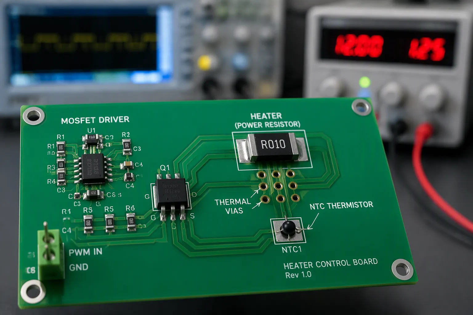
Where you place the sensor matters as much as which part you pick. Keep the temperature sensor away from power transistors and regulators, because local hot spots spoil the reading. Connect the sensor to the heater through an exposed pad or thermal vias. Keep excitation current low so self-heating does not shift the reading. A slow thermal time constant from heavy copper pour or encapsulation adds lag, and lag invites overshoot.
Build an error budget for the measurement path. ADC resolution sets the smallest step you can detect. Reference drift shifts every reading as temperature changes. Trace resistance and thermoelectric effects add small offsets, so use four-wire Kelvin connections for a Pt1000. Add these terms up and compare the total against your allowed set-point tolerance.
Heater Drive and Thermal Coupling
A MOSFET or solid-state relay with PWM gives efficient heater drive. Zero-cross switching suits resistive heaters because it keeps EMI low and avoids inrush concerns. Pick the device with margin to spare. Omron advises multiplying RDS(on) by 1.5 when the load exceeds 80% of the rating, so power dissipation = load current squared × RDS(on) × 1.5. Linear drive removes switching noise but burns the extra voltage as heat. Most pid temp controllers in board designs use PWM for that reason.
Copper pours carry heat as well as current. Place pour close to regulators and high-current ICs, and connect every island to a larger plane. A grid of thermal vias under a power package lowers junction temperature noticeably. Keep ground planes continuous and stitch edges to chassis ground.
Keep the noisy power stage apart from analog sensing. Give the analog section its own power domain, route sensitive traces away from the switching node, and never cross a ground-plane split. Shield the sensor with a guard ring where space allows. These steps keep the process variable clean, so your pid control loop acts on real data. Good thermal coupling and clean sensing together deliver precise temperature control.
Tuning, Fail-Safe Design, and DFM Trade-Offs
PID Tuning and Anti-Windup
Вы можете tune a thermal loop with the Ziegler-Nichols method. Set the integral and derivative gains to zero, then run in proportional-only mode. Slowly raise the proportional gain until the system oscillates in a steady way. Keep safety limits and stops on, because the oscillation is on purpose. At that critical point, record the ultimate gain Ku and the ultimate period Tu. Then figure out the gains: Kp = 0.6·Ku, Ki = 1.2·Ku/Tu, and Kd = 0.075·Ku·Tu. A fast actuator with Ku = 8.0 and Tu = 0.4 s gives Kp = 4.8, Ki = 24.0, and Kd = 0.24. A slow heater with Ku ≈ 2.5 and Tu ≈ 5 min gives much smaller, slower gains. That result shows thermal lag. Relay auto-tuning is a handy option when testing by hand is unsafe or not practical.
Anti-windup protects the loop during warm-up. The integral term keeps adding up error while the heater stays at full output, and that stored value then causes a big overshoot. Clamp the integral term or stop integration when the output maxes out. A well-tuned pid loop then holds the set-point without a long recovery swing.
Hardware Cutoff and Manufacturing Constraints
Software alone cannot promise safety. A shorted MOSFET or welded relay keeps the heater on even when the MCU says off. Add a separate high limit shut-off path.
Подход | Основные компоненты оборудования | Cutoff Behavior |
|---|---|---|
Comparator-based cutoff | Thermistor + comparator with hysteresis | Digital shutdown signal, simple trip point |
Voltage-reference trip | NTC thermistor + TL431 + resistors | TL431 pulls cathode to ground near 2.5 V and forces power-down |
Op-amp bridge | Thermistor + op-amp + 3 precision resistors | Bridge sets the limit without a reference |
Auto-resetting thermal fuse | Resettable thermal fuse | Opens at threshold temperature, independent of control |
A thermistor-based control loop alone cannot promise safety when the switching element fails short. Fail-safe design needs a path that cuts power on its own, apart from the control signal.
DFM brings its own trade-offs. Dissipation factor, CTE mismatch, and moisture absorption all affect thermal reliability. Thicker copper, thermal vias, and copper pours spread heat, but keep adequate spacing between a pour and nearby traces. Thermal relief spokes help пайке but hurt conduction, and a starved thermal can solder unevenly. Talk with your CM about via capping early.
PID temperature control protects a PCB by comparing sensed temperature to a setpoint and correcting the output. The proportional, integral, and derivative terms each play a part. The proportional term answers present error, the integral term clears steady-state offset, and the derivative term damps fast rises. Hardware cutoff stays as the backstop.
You should treat thermal control as core reliability work. Tune the loop, add anti-windup, and budget sensing error. Match heater drive and thermal coupling to the load. Then check every choice against manufacturing limits. PID controllers earn trust through careful design, not luck. Proportional integral derivative tuning plus a fail-safe path keeps boards safe.
FAQ
How often should the pid loop sample the board temperature?
Sample faster than the thermal time constant of your sensor and heater assembly. A loop that samples slower than the board heats will always lag the real temperature. Match the sample rate to your sensing method, then confirm the timing during validation.
Can I run a pid loop without the derivative term?
Yes. Many thermal loops run as PI only. The derivative term damps fast rises, but it also amplifies sensor noise. You should start with P and I, then add a small, filtered D term only if overshoot remains a problem.
What happens if the heater MOSFET fails shorted?
The heater stays on regardless of what the firmware commands. This is why you need an independent cutoff path, such as a comparator trip or a resettable thermal fuse. Software pid controllers cannot protect against a failed switching element on their own.
How do I keep sensor noise out of the control loop?
Keep the analog sensing path away from the switching node, give it a clean power domain, and filter the derivative term. You should also verify the reading against a reference thermometer before you lock the set-point during tuning.
Thermal design rewards patience. Validate each layer, from sensing to cutoff, and your board will hold its target for years.