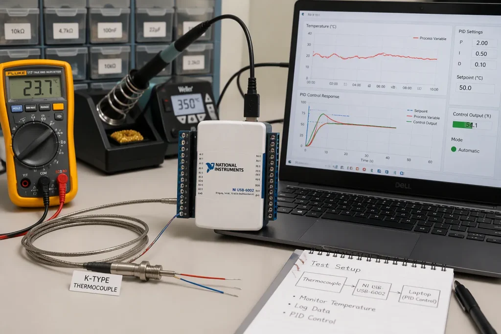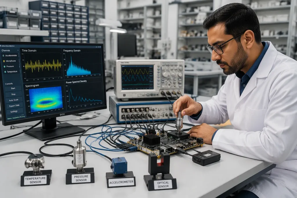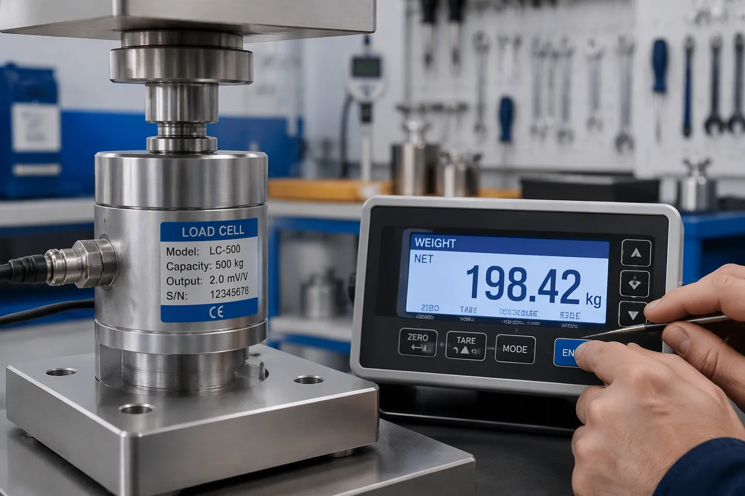
High-precision load sensing uses a load cell and an analog front-end chain to capture weight with very little error. Display control is the processing, filtering, and presentation layer that turns those measurements into readable values. Together, they set the accuracy and reliability of modern weighing systems. Functional weighing indicators alone are a market of USD 197.0 million in 2025, with a projected 5.89% CAGR through 2033, so board-level decisions carry real weight. Errors enter the signal chain at the bridge, the amplifier, the reference, and the layout. Engineers must judge component tolerance, grounding, filtering, and manufacturing trade-offs when they specify, integrate, or troubleshoot a weighing system. This discussion moves from the analog front end through precision metrics, display and EMC, and finally DFM guidance.
কী Takeaways
একটি দিয়ে শুরু clean analog front end to pick up accurate weight signals.
Use ratiometric referencing to cancel noise and drift in the excitation signal.
Get usable counts from the noise you measure, not from the ADC bit depth.
Use temperature compensation so the readings stay steady in different conditions.
Design for EMC and DFM to protect precision from production to field.
High-Precision Load Sensing Front End
The front end sets the limit for everything after it. A clean bridge, a steady excitation source, and a well-referenced analog-to-digital converter decide how much real signal reaches the firmware. High-precision load sensing starts here, and no amount of digital filtering can bring back information the analog chain never captured.
Load Cell Bridge and Excitation
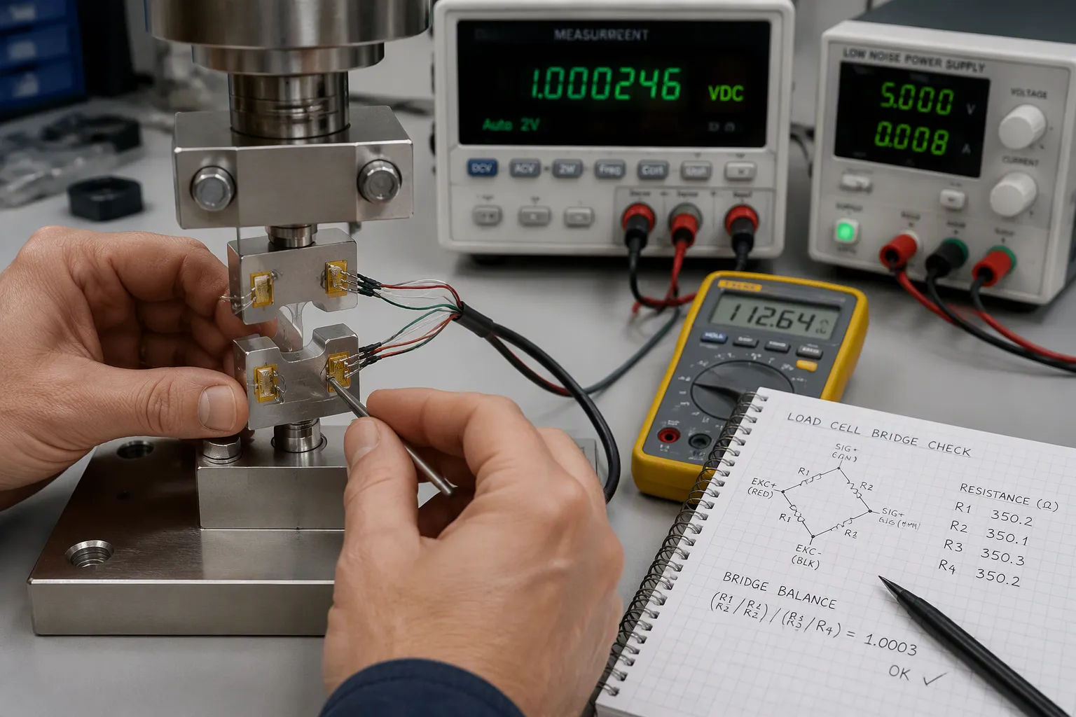
A strain gauge load cell uses a Wheatstone bridge. Four arms of resistive foil are bonded to a flexure. Applied weight stretches two arms and compresses the other two. The resistance change is tiny, often a fraction of an ohm, and the bridge turns it into a small differential voltage. That voltage scales directly with excitation: output equals excitation voltage times the fractional resistance change divided by four, for a quarter-bridge under small strain. With 2.5 V excitation and a gauge factor of 2.0, a 1000 microstrain input gives only about 1.25 mV. This is why amplification and a low-noise reference matter so much.
Excitation choice trades sensitivity against self-heating. Higher voltage raises the output and improves signal-to-noise ratio, but it also heats the gauges and drifts the zero point. Nominal bridge resistance shapes that trade-off:
নামমাত্র প্রতিরোধ | সাধারণ ব্যবহার | কী ট্রেড-অফ |
|---|---|---|
120 Ω | General-purpose measurement | Larger output signal; higher self-heating risk |
350 Ω | Precision and long-duration tests | Reduced self-heating for a given excitation voltage |
1000 Ω | High-accuracy transducer applications | Lowest self-heating; requires lower-noise amplification |
For steel, a power density of 2 to 5 W/in² is recommended. To find the best excitation, apply no load and raise the voltage while watching the zero reading. Once the zero becomes unstable, lower the excitation until stability returns. Run this test at the highest expected measurement temperature. Higher-resistance gauges lower power per unit area and allow more excitation headroom.
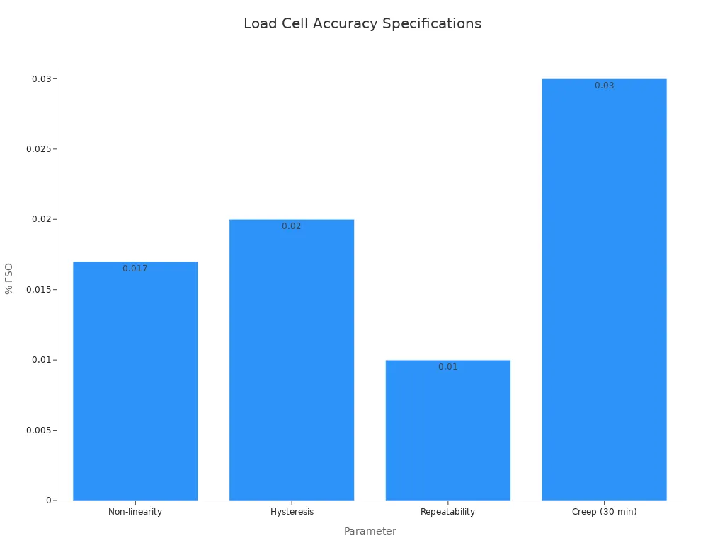
For a 100g load cell, non-linearity, hysteresis, and repeatability are controlled to ≤±0.05% R.O., corresponding to an error range of ±0.05g.
Ratiometric ADC and Amplifier Design
A ratiometric reference takes the ADC reference from the bridge excitation supply. The measurement then depends on the ratio of bridge output to excitation, not on the absolute excitation value. Noise and drift in the excitation source cancel out. This one design choice removes a whole class of thermal drift errors and makes the power supply simpler.
Gain selection deserves equal care. An instrumentation amplifier multiplies the millivolt-level bridge signal up to the converter’s input range. Gain error and gain drift add directly to total error, and a fixed external gain stage adds noise that a converter’s internal programmable gain amplifier avoids. Input-referred noise falls as gain rises inside the converter, so many designs route the bridge straight into the ADC’s internal PGA.
Dedicated converter ICs, such as the HX711 class, bundle excitation, amplification, and conversion in one package. They suit cost-sensitive designs. For tighter load cell performance, discrete or higher-grade converters with ratiometric referencing give better noise-free resolution. About 20,000 noise-free scale counts are needed to reach 1 g resolution on a 20 kg load cell. With 2 mV/V sensitivity and a 10 kg load cell, better than 1 g resolution is achievable using recommended settings. Load cell selection and converter choice therefore belong in the same decision, not separate ones.
Accuracy and Precision in Weighing Systems

Engineers often think accuracy and precision mean the same thing. They are actually separate properties, and a weighing system can have one without the other. Accuracy describes how close the reading is to the true mass. Repeatability describes how tightly repeated readings cluster around each other. Resolution describes the smallest step the display can show. A scale can repeat perfectly and still read wrong, and a scale can show many digits and still drift. Modern industrial weighing systems demand all three, and the board design decides how much of each you can keep.
Resolution vs. Noise-Free Counts
Raw converter resolution is just a number on a datasheet. A 24-bit ADC offers a 24-bit output word, and that word is the ceiling. Effective resolution is lower, because noise occupies the low bits. Noise-free counts describe the stable, flicker-free portion of the range, and this is the figure that matters for a weighing system.
The gap is large. A 24-bit converter running at a gain of 128 delivers about 19.1 bits of effective resolution with 70 nV rms noise over a ±39.1 mV input range and a 2.5 V reference. At a gain of 1, effective resolution reaches about 21.6 bits with 1.53 µV rms noise over ±2.5 V. Effective resolution runs about 2.7 bits better than noise-free resolution unless the data-output word limits it. In count terms, that 19.1-bit figure works out to roughly 489,178 noise-free counts. Weigh scales typically need about 50,000 noise-free counts, so the headroom exists, but only when layout and filtering protect it.
সম্পত্তি | এটা কি পরিমাপ | সাধারণ সীমা |
|---|---|---|
সঠিকতা | Closeness to true mass | Set by calibration and drift |
repeatability | Spread of repeated readings | Set by noise and mechanics |
সমাধান | Smallest displayed step | Set by noise-free counts |
Do not size a high-precision scale from the ADC bit count alone. Derive the usable counts from measured noise at the target gain and filter setting.
Temperature Compensation and Zero Tracking
Temperature moves both the zero point and the span. Traditional metallic strain gauge systems drift 0.01% to 0.05% of full scale per °C. Advanced designs with temperature compensation hold below 0.002% of full scale per °C. An uncompensated load cell facing a 10 °C rise can shift its output by up to ±0.05% of full scale. That shift is a real error on the display, not a rounding artifact.
ক্ষতিপূরণ পদ্ধতি | শক্তি | মূল্য |
|---|---|---|
Thermistor-based excitation adjustment | Auto-adjusts bridge voltage | Slight signal reduction, slower response |
হার্ডওয়্যার ক্ষতিপূরণ | Fast real-time correction | উচ্চ খরচ |
সফ্টওয়্যার ক্ষতিপূরণ | নমনীয় এবং খরচ কার্যকর | Depends on calibration data |
নিষ্ক্রিয় ক্ষতিপূরণ | Simple, applied at build | Moderate environments only |
সক্রিয় ক্ষতিপূরণ | Handles nonlinear errors | Needs sensors and a processor |
Zero tracking and tare routines belong in firmware, and they interact with the analog chain. Auto-zero routines should run only when the load cell is stable and unloaded. Aggressive tracking hides slow drift and masks a failing bridge. Set the tracking window from the measured noise floor, and log tare events so field technicians can audit them.
Calibration Practice and Practical Limits
Calibration closes the loop between the analog front end and the display. Use a traceable reference mass set that covers the working range, and record the zero and span coefficients at more than one temperature when the application allows. Store the coefficients in nonvolatile memory with a checksum. A corrupted calibration table produces confident, wrong readings, and no filter can catch it.
Expect practical limits. High accuracy and precision in a real enclosure depends on mechanical mounting, cable routing, and warm-up time as much as on the converter. Reliable weighing performance comes from treating the load cell, the board, and the firmware as one measurement chain. Meet the accuracy requirements of the application with margin, then verify that margin on the finished unit.
Display Control for Modern Industrial Weighing Systems
Digital Weighing Indicator Design
A digital weighing indicator is where processing, filtering, and output signals all come together. The indicator takes the converter output, applies a digital filter, and drives the display. Filter strength creates a direct trade-off. Stronger filtering gives a steadier display but slows the update rate. A digital scale indicator for static tank weighing can filter heavily, while a checkweighing indicator needs a faster response.
Display divisions also shape what the operator sees. The indicator rounds to divisions coarser than the ADC resolution, and that rounding hides flicker from electrical noise and small vibration. Sample rate sets the ceiling for usable updates. Dynamic weighing runs at 1,000 or more conversions per second, and static tank or silo weighing runs at 10 to 50. Engineers should match the sample rate and filter to the application before they tune the display.
Interface, Refresh Rate, and EMC
Display driver selection follows the panel, not the other way around. Segment drivers suit bright numeric readouts, and graphic drivers support menus and soft keys. Refresh rate must stay high enough to avoid visible flicker. Keypad and touch interfaces need debouncing in firmware, and the indicator should reject contact bounce before it registers a keypress.
Industrial weighing systems demand EMC discipline at the board level. Ground the analog front end separately from the display and driver returns. Shield load cell cables, filter the excitation supply, and add transient protection at every external connector. Communication interfaces such as serial and fieldbus ports carry transients into the enclosure, so protect them at the entry point. A digital weighing indicator that survives surge testing protects every weighing function behind it.
Tip: Route display and backlight switching currents away from the analog ground plane. Shared return paths inject noise straight into the bridge signal.
Digital weighing indicators also anchor modern industrial weighing systems. The indicator runs the filters, stores calibration, and reports faults. A well-designed digital scale indicator keeps weighing data clean from the bridge to the panel.
DFM and Implementation Trade-Offs
Board-Level Design Guidelines
The choices made during উত্পাদন decide whether a good schematic makes it through production. Component tolerance is the first trade-off. A 0.1% resistor costs more than a 1% part, and the gain network directly sets span error. Spend your tolerance budget where the signal is smallest, and accept looser parts on digital rails. Testability matters too. Add test points on the bridge excitation, the reference, and the analog-to-digital converter input so production can check each stage without probing fine-pitch pads.
Layout carries equal weight. A stable, clean power supply keeps measurement noise low, so use linear regulators for the analog portion and switching regulators for digital sections. Apply star grounding, short return paths, and decoupling capacitors placed as close as possible to each IC power pin. Keep analog and digital blocks apart along the signal path, and route signals on adjacent layers at right angles to cut crosstalk. Avoid overlapping analog and digital power planes.
In mixed-signal load cell signal conditioner design, proper isolation between analog and digital circuitry is a key requisite for reliable performance.
DFM Decision
ভারসাম্য
পথপ্রদর্শন
প্রতিরোধক সহনশীলতা
Cost versus span error
Tighten only in the gain network
নিয়ন্ত্রক প্রকার
Efficiency versus noise
Linear for analog, switching for digital
স্তর গণনা
Cost versus EMI containment
Ground and power planes sandwich signal layers
টেস্ট কভারেজ
Board area versus debug speed
Add test points at every analog stage
Diagnosing Accuracy Problems
Start every investigation by isolating the hardware. Disconnect the load cell and drive the indicator with a signal simulator. A clean simulated signal points to the sensor or wiring. A distorted one points to the board. This step separates a digital weighing indicator fault from a mechanical one before you touch calibration.
Then work through the common causes. Signal jitter comes from electrical noise, mechanical vibration, and unstable supplies. Fix it with low-ripple power, proper grounding, cable shielding, and digital filtering. Drift often means moisture got in, so check insulation resistance between the leads and the sensor body. Noise that lines up with machine operation suggests EMI from drives or welding equipment. Route cables away from power lines and check for ground loops. For readings that stay consistent but wrong, check bridge resistance; a healthy 350Ω sensor reads 350Ω ± 3Ω across the signal leads. Confirm load cell selection suits the range, and verify that accuracy requirements match the calibration weights you use. Regular calibration with traceable weights protects measurement accuracy, and recalibration should follow any repair. Careful diagnosis restores precision faster than swapping parts, and most faults trace back to grounding, moisture, or calibration records.
Precision starts at the load cell bridge and the analog front end. Ratiometric referencing, amplifier gain choice, and filtering either keep that precision or lose it. Temperature compensation, calibration, EMC design, and DFM-aware manufacturing protect it.
Three decisions matter most. First, figure out usable counts from measured noise, not from ADC bit depth. Second, connect the converter reference to bridge excitation. Third, treat grounding and layout as part of the measurement chain.
Weighing technology is moving toward high-resolution digital load cells and smart load cells with built-in diagnostics. Networked digital weighing indicators will handle more of that processing. Each step keeps pushing accuracy and precision closer to the sensor itself.
FAQ
How does a team verify high-precision load sensing before calibration?
A signal simulator takes the place of the লোড কোষ and sends a known millivolt input to the front end. A clean response confirms the board is good. A distorted response points to the analog chain. Teams should first check excitation, reference, and converter input at their test points. High-precision load sensing depends on that stage-by-stage verification.
Why does the display show fewer stable counts than the converter datasheet promises?
Datasheet resolution is only a ceiling. Noise fills the low bits, so noise-free counts set the usable range. A 24-bit converter at gain 128 gives about 19.1 bits of effective resolution. Teams should get counts from measured noise at the target gain and filter setting, not from the bit count.
What causes drift that survives calibration?
Moisture ingress, thermal gradients, and ground loops all move the zero point. A 10 °C rise can shift an uncompensated load cell by up to ±0.05% of full scale. Teams should check insulation resistance, warm the unit to operating temperature, and confirm the tare log before touching calibration coefficients.
Which indicator features matter most for an industrial installation?
Surge protection at every external connector matters first. Communication interfaces carry transients into the enclosure, so protect them at the entry point. A digital weighing indicator should also store calibration with a checksum and report faults. The digital scale indicator then keeps weighing data clean from bridge to panel.