High-precision weight sensing and display means weight measurements that are accurate, reliable, and repeatable, which improves how well the whole system performs. For hardware engineers working at the board level, the gap between standard and high-precision measurement is rarely just one component. It is the accumulated error of the whole chain.
Standard weight sensors often give good enough readings for rough tasks. High-precision weight sensing needs tighter control of excitation stability, amplifier noise, ADC resolution, and layout. The Federal Highway Administration reports that adding high-precision sensors and advanced algorithms to modern Weigh-In-Motion systems cut measurement errors by up to 30%. This shows that precision depends a lot on careful design, not just on the load cells.
The sensor-to-display signal chain, the display strategy, and board-level manufacturing factors all work together to set the final precision.
主要なポイント(要点)
High precision comes from the whole system, not just one part.
Use ratiometric measurement to cancel excitation drift.
Keep sensitive analog traces short and keep them away from noise.
Check the calibration often to keep it accurate over time.
Think about cost and accuracy early when you design.
Defining High-Precision Weight Sensing with Load Cells
Strain Gauge Bridges and Signal Behavior
A load cell turns force into an electrical signal in two steps. First, the force bends a mechanical part, and the strain gauges glued to it stretch or squeeze along with it. Second, a Wheatstone bridge turns that resistance change into a voltage. The gauge factor sets how much the resistance shifts for a given strain. So the bridge output stays in the millivolt range and must be amplified before it can be digitized.
You should think of the bridge as a balanced network. With equal arms and no load, the output voltage is zero. Any small resistance change in one or more arms unbalances the bridge and makes a differential voltage. Quarter, half, and full-bridge layouts trade sensitivity against temperature behavior, and full-bridge setups are common in precision load cells. This is the base of all resistance strain gauge weight sensor designs.
重要な精度仕様
Accuracy is not one number. Resolution, repeatability, linearity, and drift each describe a different way a system can fail, and weighing systems must plan for all of them. Linearity is the gap from an ideal straight line across the range, often below ±0.017% FSO in precision load cells. Repeatability is the spread between identical loadings, and drift covers slow changes from temperature, creep, or noise.
ロードセルの種類 | Nonlinearity (% FS) | Hysteresis (% FS) |
|---|---|---|
Conventional strain-gauge | ±0.05 | ±0.05 |
Thick-film strain-gauge | ±0.2 | ±0.2 |
油圧 | ±0.3 | ±0.2 |
Standard weight sensors often accept ±0.1% of full scale. High accuracy work in pharmaceuticals or lab testing may need ±0.01% or better. You should list each term on its own, because a weight sensor with good linearity can still fail on repeatability. That difference separates standard measurement from high-precision weight sensing.
Tip: Ask suppliers for nonlinearity and hysteresis data at multiple capacity points, not a single headline figure.
The Weight Sensor Signal Chain on the PCB
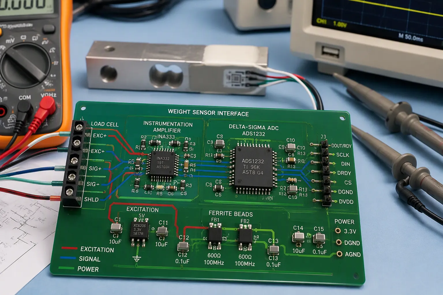
Excitation Stability and Ratiometric Measurement
The bridge needs a steady excitation voltage. Common values are 5 V and 10 V DC. A load cell’s output is ratiometric to that excitation, so a 0.01% change in excitation causes a 0.01% change in the measured output. You should check that the excitation source can drive the total resistance of all connected load cells, including cable resistance.
Ratiometric measurement removes most of this problem. The ADC uses the excitation voltage itself as its reference. Signal and reference then move together, and the digital reading stays the same when excitation drifts slowly. An absolute system uses a fixed internal reference instead, so every excitation fluctuation goes straight into the reading. Most industrial weighing systems depend on the ratiometric approach. Check that your indicator or amplifier is truly ratiometric, because low-cost units often are not.
Load cell signal conditioners must provide stable, regulated excitation voltage to power the strain gauge bridge. Excitation stability directly affects measurement accuracy because the load cell output is ratiometric to the excitation voltage.
Fast transients can still get through. Use a low-noise linear supply, and add LC filtering to switching supplies. Route excitation and signal wires away from power cables. A dedicated excitation supply for the load cells, plus ferrite beads or common-mode chokes on the excitation lines, helps in noisy environments. Ground loops inject noise into both excitation and signal, so keep the return paths separate.
Instrumentation Amplifiers and Delta-Sigma ADCs
The amplifier must raise a millivolt signal without adding noise. Aim for common-mode rejection of at least 100 dB at DC for industrial and medical precision work, and check AC rejection at the actual signal frequency, since it drops as frequency rises. Watch input offset and drift: at a gain of 100, a 50 µV offset becomes 5 mV of output error. Zero-drift chopper architectures suit the lowest-offset designs. Use 0.1% or better gain-setting resistors, and confirm gain-bandwidth product at your operating gain.
パーツ | Key low-noise / precision specs | Suitability for weight-sensor chains |
|---|---|---|
INA128 (TI) | 50 µV Vos, 120 dB CMRR (G≥100), gain 1–10,000, 700 µA Iq | Bridge sensors, thermocouples, ECG front-ends |
INA118 (TI) | 50 µV Vos, 110 dB CMRR (G=1000), 70 kHz BW @ G=100, ±40 V input protection | Low-power portable instruments, data acquisition |
AD8221 (ADI) | 60 µV max Vos, 80 dB CMRR min (G=1), low drift | Precision industrial & medical instrumentation |
AD620 (ADI) | Gain 1–10,000, low cost, single-chip simplicity | General sensor amplification, ECG, weigh scales |
LT1167 (ADI) | Low noise, high precision, single external gain resistor | Industrial process control, automotive sensors |
INA828 (TI) | Next-gen INA128 replacement: lower noise, lower power, same pinout | Drop-in upgrade for INA128-based designs |
A 24-bit delta-sigma ADC comes after the amplifier. Its built-in PGA offers gains from 1 to 128, and the converter can reach up to 23-bit ENOB. A programmable FIR filter gives 50 Hz and 60 Hz notch filtering at the same time, which blocks mains interference. An on-chip LDO regulator and calibration registers reduce the number of external parts. This architecture suits bridge measurement in weigh scales and strain gauges, where resolution matters more than sample rate. A digital weight sensor built this way resolves very small force changes. Noise-free counts, not raw bit depth, tell you the real usable resolution of the weight sensor.
Board Layout for Weight Sensors
Shielding, Guarding, and Star Grounding
Weak analog signals from weight sensors need to be kept apart from noisy circuits. Place the amplifier and converter stages near the signal source. Short traces pick up less interference. Keep weight sensor traces away from switching regulators, oscillators, and high-speed digital lines. If lines must cross, cross them at a right angle instead of running them parallel. Spacing traces at least three times the trace width apart helps isolate sensitive lines in tight layouts.
Star grounding protects precision. Send each return path back to one common point on its own. Shared-impedance errors go away when op-amp supply returns reach the star point on their own traces. Guard rings around high-impedance nodes stop surface leakage, and conformal coating keeps humidity from slowly hurting accuracy. Ground planes shield sensitive traces and give return paths a shorter route.
技術 | 対処された問題 | ガイダンス |
|---|---|---|
パーティショニング | Crosstalk between signal classes | Separate low-level analog from digital |
スターグラウンディング | Ground-loop error voltages | One common return point |
ガード | Surface leakage at high impedance | Guard rings on both board sides |
グランドプレーン | Return-path interruptions | Avoid plane splits under signals |
Mechanical Mounting, Creep, and Off-Center Loading
Mounting decides whether precision load cells give their rated accuracy. Side loading and uneven surfaces create stress points that calibration cannot fix. Mount each load cell on a stable, level surface, and line up the applied force with the sensing axis. Rigid mounting that blocks thermal expansion warps stress distribution as temperature changes.
Creep is slow deformation under a steady load. It drifts the output of weight sensors and adds nonlinearity. Take readings quickly when you can, and set up regular calibration to catch drift. Off-center loading creates bending moments that cause span errors that change with load position. Corner correction with trim resistors or a digital indicator fixes this in weighing systems. Modern quality load cells hold long-term stability better than ±0.02% of rated capacity per year. Treat every weight sensor in the chain with the same care, because one weak mounting point limits the whole measurement.
Tip: Check that all load cell mounting surfaces are level and coplanar before you run corner tests.
Calibration and Accuracy in High-Precision Weight Sensing
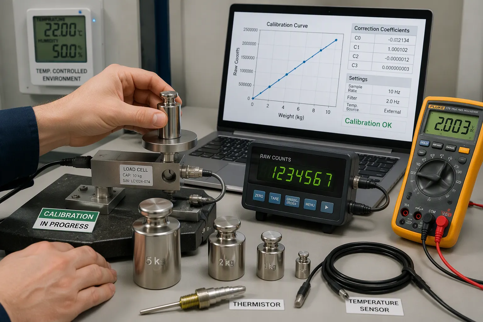
Temperature Compensation and Span Calibration
Temperature changes move the zero point and the span of every bridge. You should plan for both effects when you design the system. Matched strain gauges help with this. Place the gauges so heat changes affect them equally and cancel out. A full-bridge layout does this well. Load cell bodies made from low-thermal-expansion alloys also keep the shape stable as the room warms or cools.
Several compensation methods exist, and each one trades cost against capability.
方法 | 仕組み | 主な特徴 |
|---|---|---|
Thermistor excitation adjustment | Thermistors change bridge excitation to offset thermal effects | Slightly lowers signal amplitude (~10%) and slows thermal response, but improves stability |
Hardware compensation | Extra temperature sensors and circuits correct output in real time | Fast response; higher cost |
ソフトウェア補償 | The processor applies a temperature-correction model | Flexible and cost-effective; depends on precise calibration data |
Passive compensation | Fixed resistors counter first-order errors, added at manufacture | Works in moderate environments; cannot handle complex thermal behavior |
能動的な補償 | Built-in sensors measure ambient conditions; a microprocessor computes real-time corrections | Handles nonlinear errors; improves accuracy in dynamic environments |
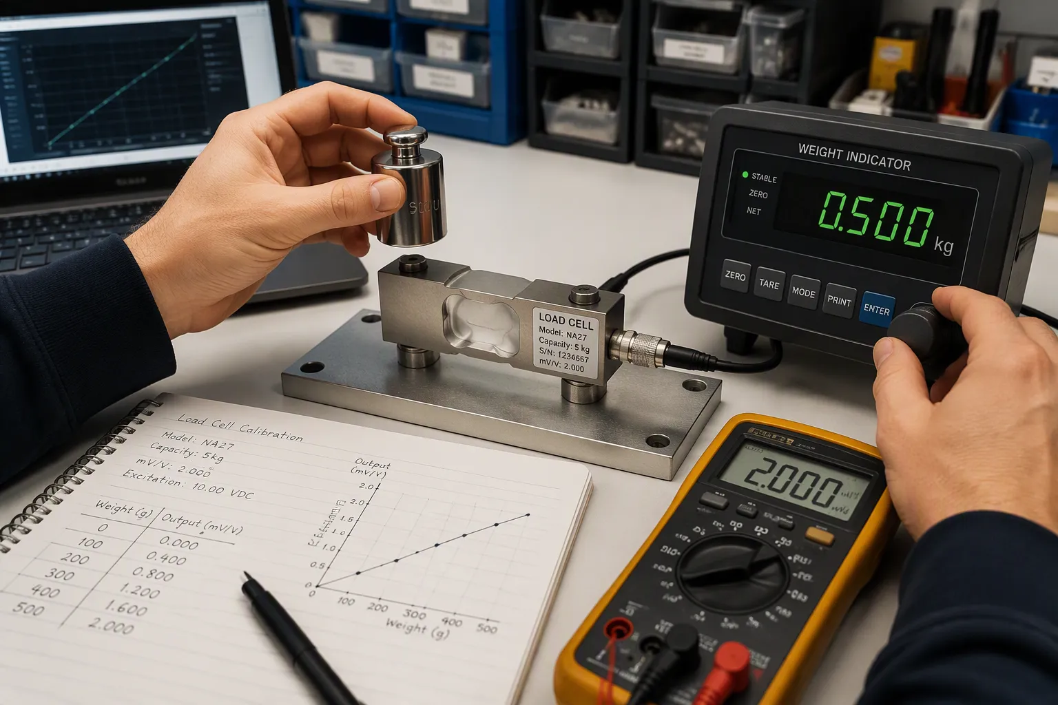
Zero-point compensation flattens the zero-drift curve, which gives you a stable starting point for high-precision weighing. スパン校正 comes next. Apply known masses across the range, record the raw counts, and fit the slope. Repeat the run at two or three temperatures. Store the correction coefficients in the digital weight sensor so the unit keeps repeatable accuracy after shipping.
Tip: Re-run span calibration after any mechanical rework. A new mounting bolt can shift the zero more than thermal drift does.
Display Interface and Refresh Strategy
The display is the last link in the chain, and it can ruin precision that the electronics earned. Match the displayed resolution to the noise-free counts of the converter. Showing digits the weight sensor cannot resolve makes the reading flicker, and operators lose trust in the measurement. Round the display to a stable digit and hold it.
Refresh strategy matters just as much. A fast update rate shows noise; a slow one feels sluggish. You should average over a window that covers several mains cycles, then update the display at a steady rate. Add a short settling delay after motion stops. This gives repeatable weight readings instead of a number that hunts.
Readability completes the job. Use a clear font, good contrast, and units placed next to the value. For a highly accurate mass measurement, show stability indicators and a zero-tracking flag. These cues tell the operator when the reading is trustworthy. A well-designed interface turns raw converter counts into an accurate digital weight reading that people can act on.
Every stage matters. The load cell sets the physical limit, the signal chain protects the signal, and calibration plus display keep measurement precision over time. Treat calibration as a process, not a one-time step, and your weighing systems will deliver high accuracy across their service life.
Practical Applications and DFM Trade-offs
Industrial, Medical, and Laboratory Systems
Accuracy targets change with the job. You should pick load cells to match the task, not the datasheet headline.
アプリケーションカテゴリ | 一般的な精度要件 |
|---|---|
Legal-for-trade / metrology | ±0.02% (OIML C3) |
Most industrial process control | ±0.03% |
Cost-sensitive applications (no strict compliance) | ±0.05%~±0.1% |
Accuracy needs are different for each task: a medical scale that measures drug doses needs finer resolution than an industrial scale that weighs bulk materials like gravel or sand. That is why load cells come in different accuracy and capacity levels to fit many uses.
In drug-making and lab settings, weighing aims for very high precision and rule compliance, especially for Active Pharmaceutical Ingredients (APIs) and quality control. Good Manufacturing Practices (GMP) require accuracy down to the microgram, because even small weight changes can alter the consistency and traits of the final drug product. High-resolution lab analytical balances and laboratory analytical balances rely on weight sensors with low noise and tight drift control. A published case shows the payoff: Shumate (2018, SLAS Technology) validated a JAMS platform for tracking dispense rates in high-throughput screening. Its measured weights differed from manual operator weighing by 1.0% on average, and it gave real-time gravimetric summaries with timely alerts. The study also noted high costs and low scalability.
Design-for-Manufacturing Constraints
Every cost decision affects the error budget. Cheaper weight sensors often have wider nonlinearity and hysteresis, and you cannot calibrate that error away at the board level. You should save tight-tolerance parts for the channels that set final accuracy, and accept looser parts where the display rounds the value anyway.
Assembly choices matter too. Connector and cable resistance adds to the bridge circuit, so specify low-contact-resistance parts and test them. Solder joint quality on the amplifier and converter affects offset drift, and IPC-A-610 Class 2 inspection catches many of these defects. Conformal coating adds a process step but protects high-impedance nodes from humidity. Test time is another trade-off: a full multi-point span calibration costs more per unit than a single-point check, yet it keeps accuracy across the shipped batch. Balance these constraints early, and your precision weighing solutions will hold their measurement performance in the field.
High-precision weight sensing and display gives you measurements you can trust: accurate, reliable, and repeatable. That trust makes the whole system work better.
The lessons apply to the whole chain. Load cells set the physical limit, and how their bridge behaves defines what the electronics can resolve. Signal chain design protects that small signal. Board layout keeps noise away from it. Calibration discipline keeps accuracy over time. DFM trade-offs decide whether the design keeps its precision in volume. Weight sensors reward care at every stage, and one weak link limits the rest.
Precision demands now shape how modern measurement systems are designed. Hardware engineers who plan the full chain early will meet them.
FAQ
How many noise-free counts do I need for a stable display?
Match the digits you show to the noise-free counts of the converter. A 24-bit delta-sigma ADC gives you plenty of raw bits. The usable resolution is lower. Show only digits the 重量センサー can hold steady. Extra digits flicker and make operators trust the reading less.
Why does my reading drift even when the load is constant?
Creep, thermal effects, and excitation drift all move the output slowly. Check the mounting first. A warped surface or side load adds stress that calibration cannot remove. Then confirm the excitation source is stable and the converter is truly ratiometric. Re-run span calibration after any mechanical rework.
Should I use a ratiometric or an absolute reference?
Choose ratiometric for most weighing systems. The ADC uses the excitation voltage as its reference, so slow excitation drift cancels out. An absolute reference sends every excitation fluctuation straight into the reading. Verify the indicator is genuinely ratiometric, because low-cost units often are not.
What accuracy target fits my application?
Legal-for-trade work typically needs OIML C3 class performance. Most industrial process control sits slightly looser. Cost-sensitive products without compliance rules can accept wider tolerances. Pick load cells to match the task, and remember that cheaper weight sensors carry nonlinearity you cannot calibrate away at the board level.