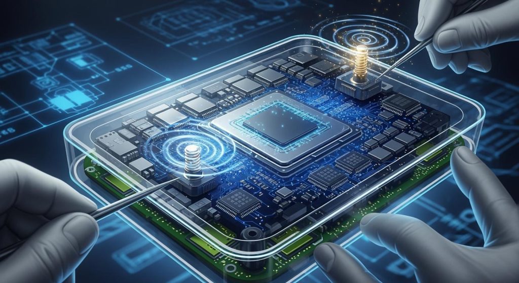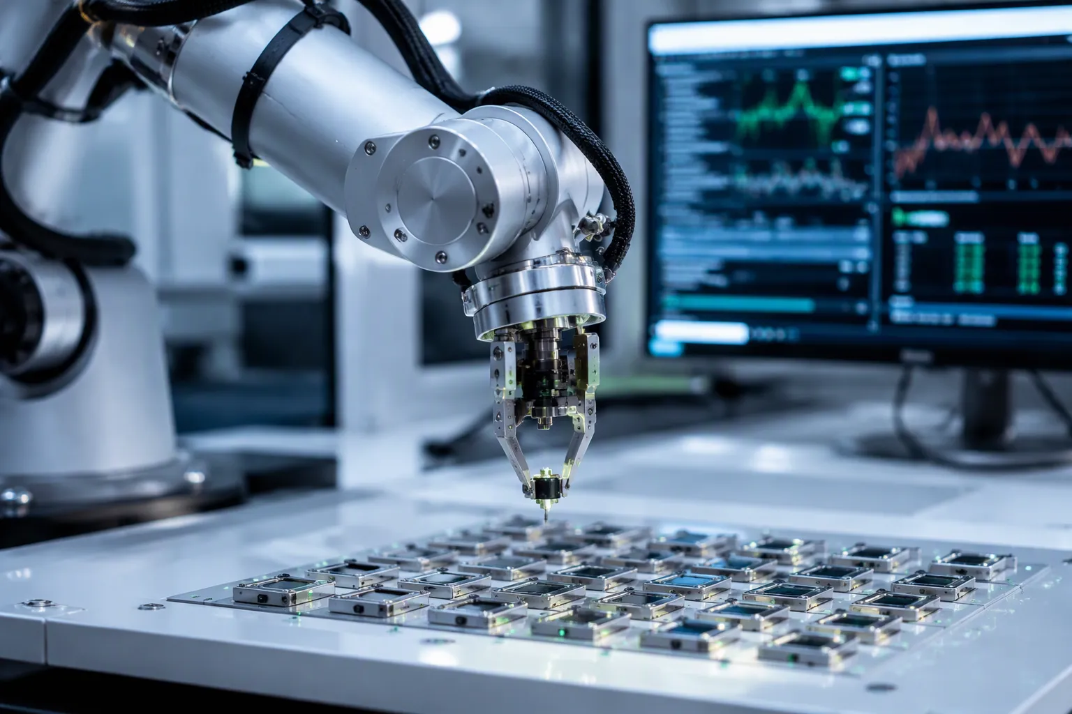
High-precision motion is the coordinated, controlled movement of mechanical systems in automation engineering. Precision motion control pairs each command with a measurement, and feedback lets the system correct its own error.
The stakes are concrete. Single-digit nanometer inaccuracies can produce a defective chip in lithography. Defects as small as a couple of nanometers can render an entire chip useless, and e-beam inspection with 1-nanometer resolution exists to catch such misprints. Wafer test and assembly face the same pressure.
Engineers who master precision motion control gain principles, key technologies, error sources, and integration strategies. Those tools support new designs and the troubleshooting of existing precision systems.
主要なポイント(要点)
High-precision motion control moves machines accurately and corrects errors using feedback.
Closed-loop feedback measures actual position and corrects deviations in real time.
Key components include actuators, controllers, drives, and feedback sensors like optical encoders.
Thermal expansion, backlash, and friction are major error sources that degrade precision.
Feedforward models and error mapping can reduce errors by over 70%.
Tune servo loops in order: current, velocity, then position for stable performance.
Regular calibration and environmental control keep precision stable over long production runs.
Match components to the task and treat precision as a system-wide property for best results.
Fundamentals of High-Precision Motion
High-precision motion means the coordinated, controlled movement of mechanical systems within automation engineering. Multi-axis synchronization keeps every axis on the same trajectory at the same instant. A single lagging axis can spoil the whole process, so engineers specify precision requirements to guarantee process performance.
コアシステムコンポーネント
Four elements form the backbone of any precision motion control system. The table below summarizes each role.
成分 | Role in the motion system |
|---|---|
Actuators (servo/stepper motors) | Convert electrical energy into mechanical force or torque to move the load |
モーションコントローラー | Interprets high-level commands, translates them into time-based low-level signals, and performs trajectory planning |
Drives (servo amplifiers) | Receive low-power command signals and modulate them into high-power current for the motor windings |
フィードバックデバイス | Continuously measure actual position and velocity, enabling closed-loop correction of disturbances |
アクチュエータとドライブ
Actuator choice largely determines system performance. Electric servo-based actuators suit high-precision work because of their controllability and responsiveness. Pneumatic and hydraulic types trade power density, speed, precision, and efficiency for high-force or rugged environments. Drives regulate voltage and current to the actuator, which gives fine control over torque, speed, and position. Modern drives add closed-loop feedback, real-time diagnostics, and embedded intelligence.
フィードバックセンサー
Feedback devices such as high-resolution optical encoders, capacitive sensors, and laser interferometers report position and velocity data to the servo amplifier’s processors in real time. Optical encoders are common in precision motion control because they deliver fine resolution and stable output. Encoders and resolvers supply continuous position and velocity feedback, so closed-loop control systems can correct errors as they arise.
コントローラと信号処理
The motion controller acts as the central processor. It interprets high-level commands and performs trajectory planning. Signal processing inside the controller turns raw sensor data into usable position feedback. Properly matched and tuned elements yield high speed, accuracy, and repeatability.
フィードバックループ
開ループ方式と閉ループ方式
An open-loop system issues commands without checking the result. A closed-loop system measures the outcome and corrects it. The cycle repeats continuously:
Feedback devices transmit position and velocity data to the servo amplifier’s processors in real time.
The control loop calculates position error by comparing the target position from the trajectory plan with the actual position from feedback.
A PID algorithm generates a corrective output: the proportional term addresses immediate error, the integral term eliminates steady-state errors such as static friction, and the derivative term adds damping to minimize overshoot.
The drive modulates the corrected command and outputs the required high-power current to the motor.
The motor converts this into mechanical force or torque, and the cycle repeats to reject disturbances and maintain positional determinism.
Gain, Bandwidth, and Stability
Gain sets how aggressively the loop responds to error. Bandwidth sets how fast the loop can react. High gain and wide bandwidth shrink errors, yet excessive values push the loop toward oscillation. Engineers balance these settings to keep precision motion control stable.
パフォーマンスメトリクス
Accuracy, Repeatability, Resolution
Accuracy measures the difference between the commanded position and the real physical position of the load, typically verified with a laser interferometer. Repeatability characterizes how closely a stage returns to the same position under identical commands. Resolution describes two properties: feedback resolution (encoder counts per unit) and positioning resolution (minimum incremental motion). High resolution does not guarantee accuracy or repeatability.
Settling Time and Following Error
Bandwidth limitations produce sloppy behavior, following errors, and slow settling. High servo-update rates and an EtherCAT-based architecture provide a good base. The resolution and linearity of optical encoders are main error sources; high pitch plus linearization in controller firmware, calibrated with external laser interferometers, improves precision. Sensor bandwidth, resolution, and accuracy directly affect settling time and following error. Precise position feedback and absolute position data further tighten both metrics across motion control systems.
Principles of Precision Motion Control
多軸調整
Synchronized Motion Across Axes
Every axis in a precision motion control system must start, hold speed, and stop at the same instant. Motion controllers derive timing from internal oscillators, so their frequencies drift apart during long moves. The standard remedy is explicit synchronization: one controller acts as master and sends a strobe signal to the slave controllers. A single multi-axis controller solves the problem automatically, because all loops share one master clock. Deterministic networks such as EtherCAT and PROFINET IRT synchronize node oscillators to nanosecond-level accuracy, so commands apply at the same instant on every drive. Electronic gearing and CAM tables add another layer, enforcing master-to-follower ratios in real time.
Trajectory Planning Basics
The controller turns each move command into a time-based trajectory that defines path, speed profile, and target position. Good planning respects dynamic limits on acceleration and jerk, and it keeps every axis synchronized throughout the move. Engineers choose the parameterization to suit the task: piecewise-cubic polynomials for dynamic planning, and B-splines for kinematic optimization, where the convex hull property keeps position and derivative limits linear for all time. S-curve acceleration, look-ahead, and circular interpolation round out the common profile types.
Servo Control Fundamentals
High-Speed Servo Loops
Real-time code typically runs 10kHz以上 to guarantee timely error correction. Each cycle, the controller compares commanded position against measured position, and a PID algorithm generates a corrective signal. Servo motors pair a high torque-to-inertia ratio with closed-loop feedback, which yields micron-level linear precision and rapid adjustment to load changes. High-resolution optical encoders placed close to the tool’s point of action, following the Abbé principle, minimize measurement error.
Stability and Response Trade-offs
Speed and precision pull against stability. Wide bandwidth and high gain shrink following error, yet excessive values excite mechanical resonance and push the loop toward oscillation. Engineers balance the two by tuning each axis and checking cross-axis interactions, since acceleration on one axis can excite vibration on another.
精密仕様
Specifying Accuracy and Repeatability
メトリック |
| 主な制限要因 |
|---|---|---|
精度 | How closely the system reaches an absolute commanded position; measures deviation from the true target | Mechanical geometry, thermal drift, calibration quality |
再現性 | How closely the system returns to the same position repeatedly, from one direction or both | Often easier to achieve than absolute accuracy; critical for consistent quality |
Matching Specs to Process Needs
A practical rule governs specification: stabilize precision first through fixturing, environment, and trained operators, then correct accuracy through calibration and offset. A system that cannot repeat consistently will not become useful through calibration alone. Teams confirm precision with a ゲージR&R研究 before they address absolute accuracy. This discipline keeps a precision motion control system honest, and it protects the investment in optical encoders, drives, and controllers.
キーテクノロジー
Optical Encoder Technology
動作原理
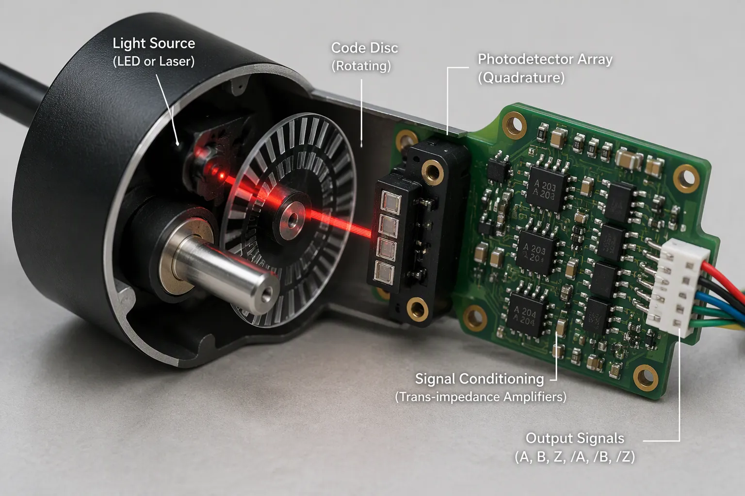
The fundamentals of optical encoders rest on a simple light path. A precision LED or laser source in the near-infrared band (850–940nm) emits a stable beam. That beam passes through a code disc with alternating opaque and transparent segments, which modulates the light as the disc rotates or translates. A photodetector then converts the modulated light pulses into an electrical current. The sequence below traces the full signal chain.
A precision LED or laser source (near-infrared, 850–940nm) emits a stable light beam.
The beam passes through a code disc or code wheel with alternating opaque and transparent segments, which modulates the light as the disc rotates or translates.
A photodetector (photodiode or phototransistor) converts the modulated light pulses into an electrical current.
Quadrature detection with four photosensitive elements spaced 90° electrically apart, plus differential configurations, maximizes noise immunity.
Signal conditioning (trans-impedance amplifiers, automatic gain control) produces a clean digital output representing position, direction, and speed.
That final output carries position, direction, and speed data. Quadrature encoding lets the controller read direction from the phase relationship between channels. Quadrature signal analysis further refines resolution by decoding every edge transition.
種類とメリット
Engineers classify optical encoders by motion geometry and by coding scheme. The table below maps the main types of optical encoders to their roles.
分類基準 | タイプ | 主な特徴 | 適用シナリオ |
|---|---|---|---|
運動幾何学 | ロータリー | Tracks angular position and direction; absolute or relative data | High-performance rotational systems |
運動幾何学 | 線形 | Detects linear displacement | Robotics and automation precision tasks |
コーディング | 増分 | Simple pattern; counts pulses from a start point for relative position | 一般的なモーションコントロール |
コーディング | 絶対の | Complex pattern; unique signal per position for absolute tracking | ミッションクリティカルなシステム |
コーディング | 差動プローブ | Dual-track design; enhanced noise immunity | 高干渉環境 |
The advantages of optical encoder technology are substantial. Optical encoders deliver high resolution and accuracy, with resolutions exceeding 1 million counts per revolution and sub-micron-level feedback accuracy. Response times typically fall under 1 microsecond, which enables real-time position tracking. Differential and quadrature detection provide superior noise immunity, including immunity to radio frequency interference. Direct digital output eliminates analog-to-digital conversion, which reduces processing overhead and improves reliability. IP67-rated enclosures are available for dust and water resistance, and the operating temperature range spans -40°C to +85°C. Non-contact measurement yields high reliability and long lifespan. These devices also support both absolute and incremental feedback, come in compact sizes, install easily, and draw low power.
Optical Encoders and Sensing
Optical vs. Magnetic Encoders
Optical encoders and magnetic encoders serve different conditions. The comparison below shows the trade-off.
エンコーダータイプ | Resolution & accuracy | 環境耐性 |
|---|---|---|
オプティカル | Highest resolution and accuracy | Vulnerable to contamination |
磁気 | 限られた解像度 | Survives harsh environments (high shock/vibration); uses Hall-effect sensing for absolute signal |
An optical rotary encoder wins on resolution, yet contamination degrades its scale. A magnetic unit sacrifices resolution for survival in harsh settings. Designers weigh both factors against the duty cycle of the machine.
Interferometers and Capacitive Sensors
Diffraction-based optical encoders can satisfy the conflicting demands of compactness, low cost/weight, and high performance more readily than alternative technologies such as distance-measuring interferometers, capacitance probes, and LVDTs.
レーザーエンコーダー deliver high-resolution, low-cyclic-error linear and multi-DoF position measurement. They merge the measurement performance of a displacement interferometer with the ease of use and installation of conventional tape or glass scale encoders. For most precision motion control system builds, this blend of performance and simplicity decides the sensor choice.
Controller Architectures
PID and Advanced Algorithms
PID servo algorithms remain the simplest control approach. They suit simple mechanical structures. They fall short for high mass or inertia, mismatched loads, robots, gantries, and ultra-high-resolution stages. Advanced algorithms fill that gap: field-oriented control, space-vector modulation, and MIMO servo algorithms. Additional filters (low-pass, notch, biquad, zero-phase), disturbance rejection, feedforward, and adaptive control complete the toolkit.
DSPs and Motion Controllers
Some DSPs include ADCs for current measurement. They are cost-effective, yet low quality, with SNR and real resolution limited to about 10 bits, which limits position jitter and velocity smoothness. High-performance drives use 14-bit or higher ADCs with high SNR. Motion controllers generate position profiles. Advanced controllers coordinate multiple axes with multi-axis vector moves, jerk control (third-order profiles), interpolated motion, error mapping and compensation, inverse kinematics, path blending, and look-ahead. They support high-speed I/O synchronization (PEG/PSO). Servo loop update rates typically span 100 Hz 〜 20 kHz, and a uniform high update rate across all loops and axes signals a high-performance design. Digital current loops, field-oriented control, sinusoidal commutation, and space-vector modulation round out drive-level control. Integrated multi-axis MIMO control (for example, ACS MC4U) reaches the highest speed and lowest settling time. High-speed precision servo control in HDD applications demonstrates this architecture in practice, where head positioning demands extreme precision under tight feedback.
Error Sources & Compensation
Common Error Sources
Backlash, Friction, Compliance
Mechanical offset appears in two places. It shows up as misalignment during assembly, and it shows up as lost motion during a move. Backlash and compliance create a dead band at every direction reversal. Friction from axis guides adds stick-slip behavior and irregular motion. 高度な制御アルゴリズム estimate these mechanical deficiencies and correct them through encoder feedback. Mechanical binding demands inspection and alignment correction before any software fix can help.
Thermal and Environmental Errors
Temperature change causes thermal expansion, which alters scale length and measurement accuracy. Thermal effects rank among the largest error sources in precision machines. Even well-controlled facilities show temperature variations of about 1時間あたり0.5℃ and spatial gradients across the floor. Internal self-heating from ballscrew-driven stages without direct feedback adds another major source of positioning error. Modern ultra-precision machines counter this with thermal control systems accurate to 0.5°C±, and newer systems reach ±0.05°C inside the working area.
Sensor Noise and Quantization
Electrical interference from motors and drives corrupts encoder feedback. Noise artifacts also arise from poor grounding. Shielded cables, proper grounding, and filtering suppress these effects. Scale imperfections produce predictable cyclic errors, and pitch, yaw, and tilt between scale and readhead degrade signal integrity.
報酬戦略
Feedforward and Model-Based
Model-based feedforward uses kinematic models to identify error sources and applies inverse transformations to commanded positions before execution. This approach suits synchronous, repeatable errors. Documented results show over 70% reduction at reversal, and advanced strategies reach up to 96.9% reduction in mean residuals. A digital twin built on multiple linear regression links several temperature inputs to thermal distortions. One validation reduced peak-to-peak error from 82 µmから33 µm and RMS error from 7.5 µm to 2.9 µm.
Error Mapping and Calibration
Calibration moves the system through its full range, records commanded versus actual positions, and applies position-dependent corrections during operation. This method targets cyclic gear tooth and eccentricity errors, with a documented 68% reduction in maximum residual error. Closed-loop feedback control with high-resolution optical encoders handles dynamic errors in real time. Joint gap errors fell from 212 µm to under 51 µm in one harmonic drive case. Teams should schedule calibration at fixed intervals, because long-term drift persists even after compensation.
Vibration and Disturbance Rejection
Passive and Active Isolation
Passive isolation mounts absorb vibration through mass and damping. Active isolation adds sensors and actuators that cancel disturbance in real time. The choice depends on the frequency content of the disturbance and the stiffness the process demands.
Notch Filters and Observers
Notch filters suppress mechanical resonance at a known frequency without sacrificing loop gain elsewhere. Observers estimate unmeasured states and feed them back to improve disturbance rejection. Both tools extend the usable bandwidth of a precision motion control loop.
Quantified compensation performance in harmonic drive systems: feedforward reduces joint reversal errors by over 70%, gap compensation reaches 87%, and advanced strategies achieve 96.9% reduction in mean residuals. Mean residual drops from 3.379 mm to 0.105 mm.
A precision motion control system achieves its best results when engineers treat precision as a system property. Optical encoders supply the position feedback that makes correction possible, and absolute position data removes the need for homing after each power cycle. Environmental control and regular calibration keep drift within bounds. These practices let precision motion control deliver repeatable results across long production runs.
Precision Motion Control Systems Integration
デザインとサイズ
Matching Actuators, Sensors, Loads
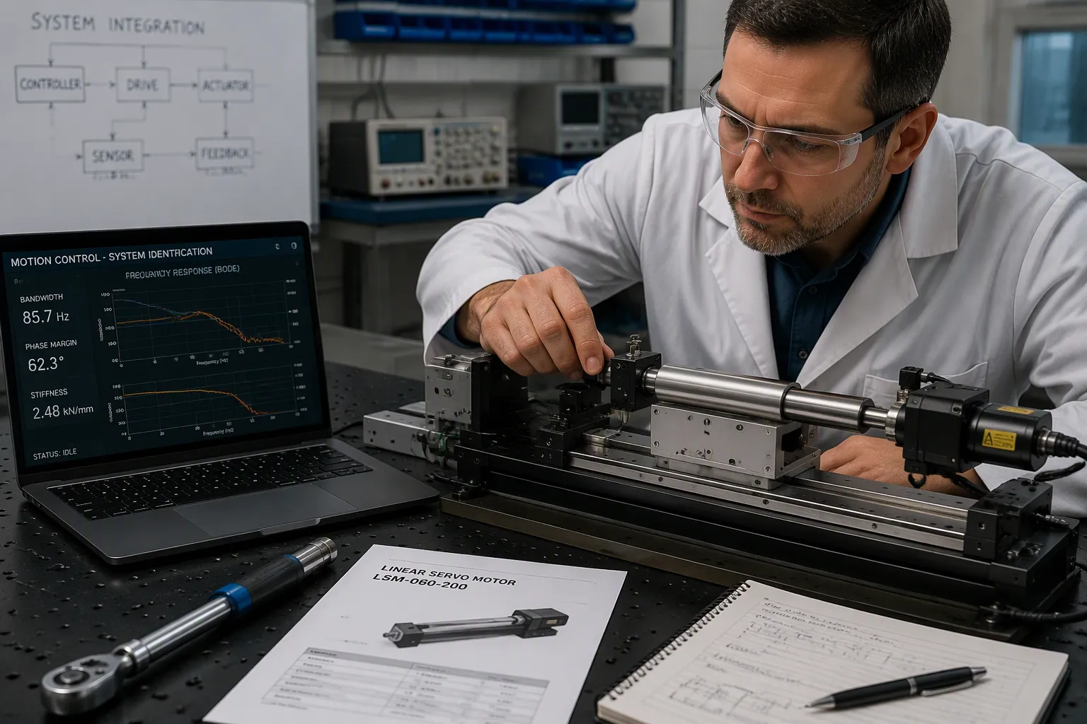
Integration begins with a clear definition of the motion task. Engineers define the motion type first: push/pull, lift, hinge, or pulley/cable. They confirm the load is guided, adding rails or slides where needed, because the actuator is not a guide rail. Next they compute the worst-case force, including friction, start loads, and geometry. They apply a safety margin, typically 1.5×~2× for real builds. Stroke, speed at operating load, duty cycle against thermal limits, and IP rating all follow. Control strategy comes next: end-to-end motion only calls for open loop, repeatable stops call for feedback, and shared loads call for synchronized closed loop. Control decisions should be finalized before wiring or fabrication begins.
Motor selection follows a similar discipline. Teams sort suggested servomotors by cost to find the lowest-cost option that meets requirements; spending about 10%以上 can add about 20% factor of safety for future scope creep. They verify the inertia ratio stays at or below the allowable limit, and they check that application speed and torque sit under the motor’s maximums. A 5:1 gearbox multiplies torque, reduces inertia by the square of the ratio, and helps stay within speed constraints. Rod-style actuators suit linear thrust-only work with high force up to 50,000ポンド, while rodless actuators carry loads and eliminate extra guiding. Moment loading (Mx roll, Mz yaw) deserves calculation for rodless units, including off-center loads and dynamic bending moments from end-of-stroke acceleration.
Bandwidth and Stiffness Trade-offs
The stage’s first flexible mode caps achievable control bandwidth. That cap enforces a trade-off between acceleration and closed-loop stiffness. Lowering stage weight pushes structural resonance frequencies toward or into the control bandwidth, which limits positioning accuracy and may cause stability challenges. Active control of low-frequency flexible modes through sequential structure-control co-design aims to break the trade-off, enabling simultaneous high acceleration and high closed-loop stiffness.
Tuning and Commissioning
Step-by-Step Loop Tuning
Commissioning follows a 固定順序, so each loop rests on a stable foundation.
Verify mechanical readiness: coupling tightness, belt tension, bearing preload, and a load that represents actual operating conditions.
Configure motor and feedback parameters: rated current, torque constant, pole count, and encoder resolution, type, and direction.
Tune the current loop; most drives auto-configure it, and bandwidth typically lands at 1〜3 kHz 標準アプリケーション用。
Run auto-tune or begin manual velocity loop tuning: start with low proportional gain, raise it until the step response is crisp without sustained oscillation, add integral gain slowly, and add notch filters for resonance peaks.
Tune the position loop: raise proportional gain until tracking error is acceptable, then add velocity and acceleration feedforward.
Validate under operating conditions across the full speed, load, and profile range.
検証と検証
Verification proceeds through installation qualification, operational qualification, and performance qualification. Installation qualification confirms correct equipment installation before operation. Operational qualification validates thermal stability, with drift held to about 10 µrad/°C via actively cooled motors and purged mirror enclosures, and confirms that closed-loop optical encoder feedback corrects torque disturbances and demonstrates sub-micron repeatability. Performance qualification verifies synchronization over a deterministic fiber-optic bus with a single clock for servo stages and galvo drives, plus trajectory tracking accuracy under velocity changes.
トラブルシューティング
Instability and Oscillation
Instability is usually physical, not algorithmic. No software can make stable decisions on unstable inputs. Engineers perform a ground-loop audit by measuring AC and DC voltage between chassis ground and sensor-mount ground; any reading indicates a ground loop that needs unification. They inspect shielding and route signal cables at least 12 inches from power lines to avoid EMI/RFI from VFDs, welders, or high-voltage lines. If noise correlates with machine operation, rubber isolators on the mounts suppress mechanical oscillation.
Repeatability and Drift
Drift troubleshooting starts with hardware isolation. Technicians disconnect the sensor and substitute a signal simulator; if drift persists on the display electronics, the fault lies in the controller rather than the sensor. They measure insulation resistance between any lead and the sensor body, where a value below about 5000 MΩ signals moisture ingress. They connect the shield wire to a clean earth ground at the indicator side to prevent slow charge accumulation. Common root causes include moisture infiltration, thermal gradients, creep, aging solder joints, and corrosion. Teams prove repeatability on real parts on the real line before chasing accuracy, and they stabilize fixtures, motion control, optics, and lighting first. This discipline protects accuracy and repeatability across the life of the precision motion system.
アプリケーション
半導体製造
Lithography and Wafer Test
Lithography demands ultra-precision stages for mask alignment, wafer positioning, and optical system positioning. Sub-micron accuracy and repeatability must hold across the full travel range, not just at a nominal position. Thermal growth in slide systems and spindle heat generation degrade that accuracy. Bearing preload, slideway geometry, and spindle runout all feed system-level error.
Wafer test and burn-in call for low-vibration motion systems and low-vibration spindle designs. Rotational noise interferes with sensitive electrical measurements. Equipment runs three shifts with minimal downtime, so components must survive continuous high cycle counts.
アプリケーションエリア | Precision Motion Requirements | チャレンジ |
|---|---|---|
Lithography & Exposure | Ultra-precision stages for mask alignment and wafer positioning; sub-micron accuracy across full travel | Thermal growth, spindle heat, system-level integration |
Wafer Test & Burn-in | Low-vibration motion systems and spindle designs | Rotational noise, high cycle counts |
Inspection & Defect Review | Stiffness-optimized, damped, precision-balanced stages | Vibration sensitivity, cleanroom compatibility |
Assembly & Wafer Handling | Precision stages for transport and end-effector positioning | Tight envelopes, traceability for qualification |
組み立てと検査
Inspection and defect review depend on stiffness-optimized, damped, precision-balanced designs. Contamination control matters here. Components must avoid particulate generation, frequent re-lubrication, and outgassing, which requires cleanroom-compatible lubrication, sealing, and surface treatments. Assembly work adds tight envelope constraints in compact platforms. Spindles, slides, and stages must perform as a unified whole, because a component that works in isolation but introduces vibration or geometric error fails the application.
医療および生命科学
Surgical Robotics and Lab Automation
Medical and life-science work tolerates almost no deviation. Precision motion control handles delicate component positioning where tolerances typically fall below 10 microns. Closed-loop architectures deliver repeatability down to single-digit microns, and teams perform tolerance stack-up and capability analysis to prove it. Vision-guided gantry systems support inspection and material handling with high-speed movement and less rework.
Lab automation and cleanroom operations rely on tailored robotic integration. Multi-axis architectures streamline assembly of small-scale components, and high-tolerance pick-and-place minimizes misalignment and damage while raising output. These tasks justify precision motion control over general robotics.
Aerospace, Optics, and Research
Telescope Mounts and Pointing Systems
Pointing instruments such as telescopes or lasers mount on moving platforms and track known targets, including ground targets, celestial bodies, and artificial satellites. Mounting the inertial navigation system directly on the instrument decouples it from platform bending and misalignment. GPS signals correct drift, and corrected pointing-angle commands stay close to zero for fine pointing. Encoder accuracy for platform steering need only match the autopilot subsystem.
A spacecraft’s pointing and attitude control system is a key component to its science performance, and benefits from being treated holistically from early in the commissioning plans.
Aerospace, robotics, and manufacturing all depend on the right linear motion technology. Precision motion control systems succeed when engineers match components to the duty cycle, and optical encoders supply the position data that keeps pointing and inspection honest. Designers who treat precision motion control as a system property, rather than a component spec, get the best results from their motion control systems. High-resolution optical encoders and disciplined integration carry precision motion control system designs from prototype to production.
ベストプラクティス
デザインと選択
Realistic Performance Specs
Engineers set realistic performance specifications before any hardware commitment. They specify load weight, center of gravity, frequency of use, desired range of motion, and environmental conditions such as temperature, vibration, and moisture. Getting these parameters right prevents costly redesigns and performance issues later. Teams also avoid common pitfalls: under-specifying critical components, ignoring environmental factors, overcomplicating the mechanism, forcing catalog parts into custom-fit applications, and skipping real-world performance testing beyond lab validation.
Control co-design strengthens precision motion control from the start. The controller design belongs in the hardware design phase, because hardware and control are strongly coupled. Designers build frequency-domain metrics such as control bandwidth and maximum disturbance sensitivity directly into the design problem. They add robustness constraints and respect physical actuator bounds. A nested optimization formulation lets an outer loop optimize hardware parameters while an inner loop synthesizes a controller. Compared with a baseline sequential approach, this method achieved 42% weight reduction and 28% bandwidth improvement on a case-study motion stage. Teams choose custom versus standard components deliberately: custom parts suit tight enclosures and precise torque control, standard parts suit time- or budget-constrained builds, and a hybrid approach sometimes works best.
メンテナンスと信頼性
校正および環境制御
Calibration and environmental control keep a precision motion control system reliable over its service life. Teams schedule calibration at fixed intervals, because long-term drift persists even after compensation. They hold working-area temperature within tight bounds, since thermal expansion alters scale length and measurement accuracy. Optical encoders reward this discipline with stable output, and regular verification confirms that position data stays trustworthy.
Reliability also depends on protecting the feedback path. Shielded cables, proper grounding, and filtering suppress electrical interference from motors and drives. Technicians inspect seals and insulation resistance to catch moisture ingress early. They route signal cables away from power lines and unify chassis grounds to remove ground loops. These habits extend the life of optical encoders and preserve precision across long production runs. A disciplined maintenance plan turns precision motion control into a dependable asset, and it protects every investment in sensors, drives, and controllers.
The guide traced one path: fundamentals, key technologies, error compensation, and integration. Precision is a system-level property. It emerges from matched components, sound feedback design, and disciplined error management. Optical encoders anchor that chain by supplying trustworthy position data.
Emerging trends reshape the field:
Absolute, magnetic, capacitive, and Sin/Cos encoders with serial interfaces replace bulky parallel wiring, reaching roughly 1 nm resolution on Sin/Cos linear stages.
Controllers running DSPs at servo rates of 10 kHz or more now record servo error and drive output, then analyze it to predict failures.
Teams should specify realistic performance targets first, then tune and validate each loop in order. That discipline turns high-precision motion into dependable production.
FAQ
What defines a high-precision motion system?
A high-precision system moves a load along a commanded path and measures the result in real time. Feedback devices report actual position, and the loop corrects any deviation. Multi-axis synchronization keeps every axis on the same trajectory at the same instant.
Why does closed-loop feedback matter more than raw resolution?
High resolution alone does not guarantee accuracy or repeatability. Closed-loop feedback lets the system detect and correct disturbances as they occur. Engineers verify real performance with a laser interferometer and a Gage R&R study before trusting a specification sheet.
How do optical encoders support precision motion control?
Optical encoders convert light through a code disc into digital position, direction, and speed data. They offer fine resolution, sub-microsecond response, and strong noise immunity. Designers pair them with absolute position data to remove homing after each power cycle.
Which error sources degrade positioning most?
Thermal expansion ranks among the largest error sources. Backlash, friction, and compliance add lost motion at every reversal. Sensor noise and scale imperfections contribute cyclic errors. Feedforward models and error mapping cut reversal residuals by more than 70% in documented cases.
How should a team tune a servo loop?
Commissioning follows a fixed order. Technicians verify mechanical readiness, configure motor and feedback parameters, then tune the current loop, the velocity loop, and the position loop in sequence. They validate the result across the full speed, load, and profile range.
When does a design need active vibration isolation?
Passive mounts absorb vibration through mass and damping. Active isolation adds sensors and actuators that cancel disturbance in real time. The choice depends on the disturbance frequency content and the stiffness the process demands.
What keeps precision motion control stable over long production runs?
Regular calibration, tight thermal control, and a protected feedback path preserve performance. Shielded cables, unified grounds, and signal routing away from power lines suppress interference. Teams schedule calibration at fixed intervals because drift persists even after compensation.
Where do optical encoders fall short?
Contamination degrades the code disc, so harsh environments favor magnetic units. Magnetic encoders trade resolution for survival under shock and vibration. Designers weigh both factors against the duty cycle of the machine before choosing a sensor.