Optimizing motor speed control stands out as one of the most effective ways to cut energy waste in motor-driven systems. Electric motors carry a heavy share of global electricity demand, so speed regulation is a high-impact lever for energy efficiency.
Makuriro | Share attributed to motor-driven systems |
|---|---|
Global electricity demand (industry + commercial buildings) | |
Industry’s electricity consumption | ~ 65% |
Properly selected variable frequency drives (VFDs) in variable torque applications typically deliver 30 - 70% energy savings. Which techniques and practices deliver the best gains? This article examines fundamentals, optimization techniques, feedback systems, practical steps, and limitations.
Zvitsva Zvitsva
Match motor speed to the load to cut energy waste and save money.
Use variable frequency drives (VFDs) for pumps and fans to save 30–70% energy.
Closed-loop control reduces power use by up to 67% compared to open-loop systems.
Size motors correctly to avoid oversizing, which wastes energy.
Regular maintenance and thermal management keep motors efficient and extend life.
Why Speed Control Matters
The Cost of Fixed-Speed Operation
A fixed-speed motor runs at one speed no matter what the load demands. This design wastes power whenever demand falls below full capacity. The motor keeps drawing near-full power while the process needs only a fraction of that output. The excess energy becomes heat, noise, and vibration instead of useful work.
Electric motors in many facilities run this way for most of the year. Systems sized for peak demand often operate part-loaded for long stretches. The waste adds up quietly on every electricity bill. Motor speed control directly attacks this problem by letting output follow demand.
Matching Speed to Load
Variable speed operation is a basic method of saving energy in motor applications. A variable speed drive adjusts motor operation to align with load variations. This alignment can significantly lower electrical bills. The drive trims energy consumption and system speed to match output demands, and that mechanism sits behind the reported savings.
VSDs adjust energy consumption and system speed to match output demands, which is the core mechanism behind the reported savings.
The gains are substantial. Typical energy savings from VSDs exceed 50%. A typical retrofit pays back in less than 3 years. Frequently part-loaded systems sometimes pay back in less than 1 year. The condition that enables these savings is simple: systems operating at part load for most of the year. Matching speed to load is therefore a core practice in motor control for energy efficiency, and it improves motor efficiency across the whole drive train.
Fundamentals of Motor Speed Control
Torque, Speed, and Load Basics
Torque, speed, and load form a linked trio in every electric motor. Power equals speed multiplied by torque. A motor’s rated output power is fixed, so speed and torque move in opposite directions. Halving the speed roughly doubles the torque at constant power.
Simba (kW) | Speed (rpm) | Approx. Torque (Nm) | Typical Pole Count |
|---|---|---|---|
11 | 3000 | 35 | Matanda makumi maviri |
11 | 1500 | 70 | Matanda makumi maviri |
11 | 1000 | 105 | Matanda makumi maviri |
11 | 750 | 140 | Matanda makumi maviri |
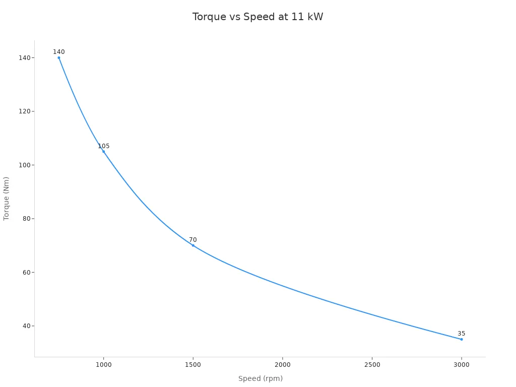
The load’s torque-speed characteristic is decisive when selecting a motor. Variable-torque loads such as centrifugal pumps and fans need torque that rises with the square of speed. Constant-torque loads such as conveyors and elevators hold torque steady at every speed, so power rises in direct proportion to speed. Constant-power loads such as winding and coiling show torque inversely proportional to speed.
Power (P) = Speed (n) × Torque (M)
Since the rated output power of a motor is a fixed value, speed and torque are inversely related.
DC Motor Control and Voltage Adjustment
Speed control methods for DC machines fall into two families. Voltage control holds the field at a fixed exciting voltage and varies the armature supply. Speed is approximately proportional to armature voltage. Flux control weakens or strengthens the field winding to move speed above or below base speed.
Electronic control now dominates. A pulse-width modulation controller switches rapidly on and off, and the duty cycle sets the average energy delivered. Fifty percent duty yields roughly half speed. This approach produces very low heat loss, which makes it the most efficient and precise option and the standard for modern brushed and brushless drives. Simple voltage reduction also works, yet it lowers available torque along with speed. Controlling motor speed this way suits predictable, constant loads. Resistance inserted in series with the armature wastes power as heat, so designers treat it as legacy practice. Gear reduction remains a mechanical alternative: output speed equals motor speed divided by the gear ratio, and output torque multiplies by that ratio and the gear efficiency.
Maitiro Ekugadzirisa Zvinhu Zvikuru
PWM and VFD Approaches
Pulse-width modulation and variable frequency drives both regulate speed electronically, yet they serve different roles. PWM switches a fixed DC supply on and off at high frequency. The duty cycle sets the average voltage, and that voltage sets the speed. This method suits DC motors and delivers low heat loss. A variable frequency drive, by contrast, converts incoming AC power and adjusts both frequency and voltage to steer an AC induction motor. VFDs excel in pump and fan systems where load torque falls with speed.
PWM carries efficiency limits tied to switching frequency. Very high frequency above 50 kHz raises switching loss and may exceed the driver’s charge-pump capacity. Higher switching frequency reduces current ripple but raises MOSFET switching losses. Ultrasonic operation above 20 kHz stays inaudible yet can increase switching loss. Frequency set too low produces audible noise or saturates the core. Engineers balance these trade-offs against the load profile.
PWM Frequency Condition | Energy-Efficiency Limitation |
|---|---|
Very high frequency (>50 kHz) | Increases switching loss and may exceed the driver’s charge-pump capacity |
Higher switching frequency (general) | Reduces current ripple but raises MOSFET switching losses |
Ultrasonic frequency (>20 kHz) | Inaudible operation, but may increase switching loss |
Frequency too low | Can cause audible acoustic noise or saturate the core |
FOC and Advanced Algorithms
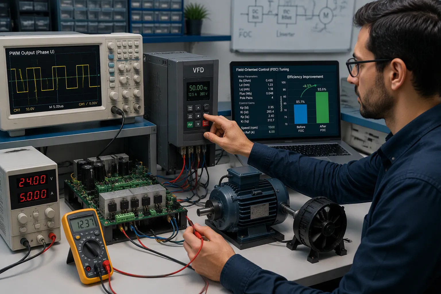
Field-oriented control transforms motor speed regulation by separating torque and flux. This separation enables precise speed control across varying conditions. Field-oriented control cuts energy losses and raises overall efficiency. Tuning the PI controllers inside an FOC scheme yields further gains. FOC-based drives also show high efficiency and power density.
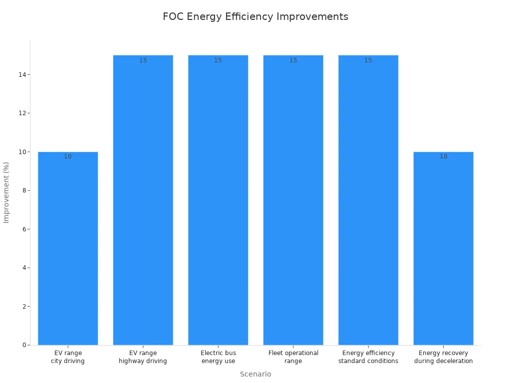
Field data shows the payoff. Electric vehicle range in city driving rises about 10% versus traditional control. Highway range with consistent FOC calibration climbs up to 15%. Electric bus energy use drops roughly 15%. Fleet operational range gains 10–20% on average with advanced FOC strategies. Optimized torque production lifts energy efficiency about 15% under standard conditions. Energy recovery during deceleration adds up to 10% range under specific conditions. These gains stem from optimized torque and flux, which reduce losses and improve energy recovery.
Application Domain | Efficiency-Related Benefit Attributed to FOC |
|---|---|
Variable frequency drives (conveyors, pumps, compressors) | Simulations used to optimize performance and energy efficiency |
EV traction motors | Regenerative braking and efficient power conversion |
HVAC air handling units | Improved energy efficiency and comfort |
Chillers uye kutonhora shongwe | Kuderedzwa kwesimba rekushandisa uye mari yekushandisa |
Compressors | Improved energy efficiency and lower operating costs |
Beyond algorithms, structural, material, and electronic advances lift motor efficiency. Improved laminations and magnetic materials cut core losses. Wide-bandgap semiconductors such as silicon carbide reduce switching loss in inverters. Advanced algorithms extend speed, position, and torque control to new precision. Together these advances make optimizing motor control for energy efficiency a layered discipline, and they strengthen motor control for energy efficiency across electric motors of every class.
Feedback Loops and Sensors
Closed-Loop Control Benefits
Closed-loop control systems compare actual output against a reference and correct the error continuously. This correction loop minimizes energy waste in a direct way. A drive no longer guesses how much power the load needs. It measures the result and trims the command until output matches demand.
The savings can be dramatic. In one comparison, an open-loop stepper system averaged 43.8 W of power consumption. A closed-loop stepper system averaged 14.2 W, about one third of the open-loop figure. That difference equals roughly 29.6 W less on average, a reduction of about 67.6%. The loop pays for itself through lower losses alone.
A closed-loop control system rests on four parts: an yekuisa chiratidzo that sets the desired response, a controller that processes the error, an actuator that adjusts the system, and a feedback path that measures output continuously. Each part supports precise speed control and steady speed regulation under changing loads.
Kusarudzwa kweSensor uye Kuiswa
Sensor choice shapes how well a motor speed control system performs. High-resolution rotary encoders serve the velocity loop in modern digital controllers. Mounted rigidly on the motor, they supply velocity feedback and keep the servo loop stable. Controllers often derive velocity mathematically from position data. Tachometers once served as dedicated velocity sensors, yet high-resolution encoders have largely replaced them.
Monitoring and analyzing motor performance supports energy efficiency over time. Teams should track active energy in kWh at several installation points and compare similar activity periods. Supply voltage should stay within plus or minus 5% of the utility-declared value. A power factor below 0.9 signals excess current draw and warrants correction. Voltage distortion above 6–8% raises losses and calls for harmonic mitigation. These readings turn motor control from guesswork into measured practice, and they keep electric motors running near their efficient range.
Optimizing Motor Control at the System Level
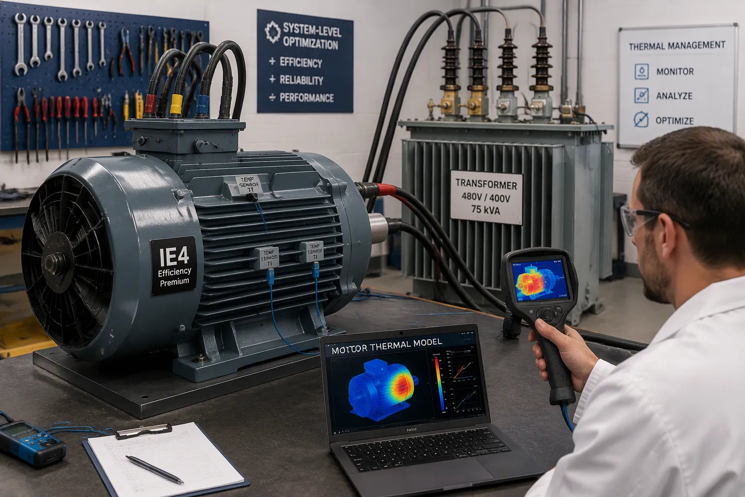
Thermal Management and Temperature Monitoring
Heat is the dominant factor limiting motor lifetime. When internal temperature exceeds insulation class limits, winding insulation degrades and eventually causes short circuits or phase imbalance. Overheating also breaks down bearing grease, and many apparent motor failures are actually lubrication failures. Excessive heat can partially demagnetize permanent magnets. Once magnet strength drops, motor efficiency falls and heat generation rises further, creating a damaging feedback cycle.
Each 10°F increase in operating temperature cuts insulation life by approximately 50%.
Motors are not designed to run at maximum allowable temperature because doing so drastically shortens motor life.
Overheating causes lubricant to evacuate bearing housings, leading to numerous bearing failures.
Designers should bond temperature sensors directly to coils, or use a joule-counter thermal model in the driver, to catch rapid localized winding heating before the housing warms. Cooling fins plus fan-driven airflow can raise continuous maximum power roughly 3× for small motors and 5× for large motors. Mounting the motor so all sides stay exposed supports uniform convective cooling. Lowering average power draw also helps, since continuous heating follows RMS force rather than instantaneous peak force.
Components, Wiring, and Maintenance
System-level gains start with the power path. Upgrading transformers and using thicker wiring reduce voltage drops, so less energy is lost before it reaches the motor. Higher-efficiency IE3 or IE4 motors use electricity more effectively, and their better thermal management lowers wear and maintenance costs. Although these motors cost more upfront, the savings can recoup the investment within a few years, especially where electric motors run continuously or under high load.
Regular maintenance protects those gains. Over-lubricating a motor builds pressure that ruptures shaft seals and purges grease into the windings, causing overheating and excessive energy consumption. Keeping a motor free of dirt and oil prevents a debris-based thermal blanket from forming. Correctly tensioning belts and chains, using matched belts, and enforcing accurate alignment all reduce motor loads. Misalignment and soft-foot conditions stress bearings and couplings, causing vibration and a considerable increase in energy consumption. Motor lifecycle cost is only 2–3% purchase price, while 97–98% goes to energy, so a scheduled maintenance program pays back through lower energy costs and downtime.
Matanho Anoshanda Okuita
Motor Selection and Sizing
Proper sizing starts before anyone orders hardware. Teams should follow a fixed sequence to avoid oversizing, which quietly wastes power for years.
Determine torque first, since rotational force is the most critical sizing factor.
Define the speed range the application needs in RPM.
Calculate power as torque multiplied by speed.
Favor high-efficiency motors such as BLDC designs, which cut energy loss and heat.
Match the duty cycle and environmental protection rating to real conditions.
Add a 20%–30% safety margin to calculated torque and power for peak loads.
Load inertia also matters. Motor inertia should not exceed 10 times load inertia, and a 1:1 to 5:1 ratio suits precision work. Right-sizing requires logged current draw over a representative period, not the nameplate rating. A motor running below 50–60% of rated load is a strong candidate for replacement. Electric motors often consume 65–70% of a plant’s electricity, so this step carries real weight.
Yepamberi Kudzora Software
Software turns a correctly sized motor into an efficient one. Variable frequency drives match speed to demand, and they can deliver kusvika ku50% simba rekuchengetedza in some applications. The affinity laws explain why: power scales with the cube of speed for fans and pumps, so small speed reductions produce large savings. VFDs also soften startup, which removes high inrush currents and peak demand charges.
Advanced drives add flux optimization, which trims losses during light-load conditions. Replacing throttling valves with speed control ranks among the highest-potential applications. Coordinated PLC control pushes savings further, and regenerative drives recover otherwise wasted energy. A VFD alone cannot fix an oversized motor idling near minimum speed, so pair it with correct sizing. Together, these tools support optimizing motor control for lasting energy efficiency.
Zvinokanganisa uye Zvinogumira
Mutengo uye Kuoma
Speed regulation delivers strong returns, yet the upfront investment and integration work can deter some teams. Purchasing and installing a drive costs more than traditional motor control hardware. Standard motors may also suffer insulation breakdown, overheating, and bearing damage from PWM output, so inverter-duty rated motors become necessary and add both cost and selection complexity.
Cost or Complexity Implication | |
|---|---|
Kutanga dura | Substantial upfront, offset over time by energy and maintenance savings |
Electromagnetic interference | Requires shielding, proper grounding, and EMI filters |
Zvirongwa uye kugadzirisa | Needs staff training and clear manufacturer documentation |
Electrical noise and harmonics | Harmonic filters may be needed and can be a regulatory requirement |
Drives lose roughly 2–3% of handled power as waste heat, so enclosures and cooling must protect the electronics. Compatibility checks matter too. Older or specialty motors may need extra filters, wiring upgrades, or replacement. A qualified technician should verify motor condition, grounding, and control settings before installation. Payback still favors most projects: AC drives in HVAC return in Makore 1-5, fans and pumps in 1–2 years, and VFD retrofits in small and mid-sized firms in 2–4 years. Those firms often demand payback under Mwedzi 18-24, so the business case needs care.
Conditions That Reduce Gains
Savings shrink under several operating conditions. Constant-torque loads still demand substantial torque at reduced speed, so gains weaken. Systems needing minimum flow, lubrication, or motor cooling limit how far speed can drop. Intermittent operation offers fewer hours to recover savings than continuously running pumps or fans.
Site conditions matter as well. Unstable power supply, including voltage fluctuations and harmonic distortion, can cut efficiency by 15 - 25% versus ideal conditions. Extreme ambient heat pamusoro pe40 °F shortens motor life, and poor ventilation or contamination compromises cooling. Even well-tuned closed-loop control systems cannot recover losses caused by a weak power path. Teams should audit these conditions before committing capital, then pair motor speed control with thermal management and maintenance discipline to protect the expected gains.
Optimized speed control links directly to power efficiency. A drive that matches output to demand stops the waste that fixed-speed operation hides on every bill. The strongest results come from combining the right technique, a solid feedback system, sound thermal management, and disciplined maintenance. No single measure carries the load alone.
Readers should now assess their own motor systems. Log current draw, check part-load hours, and confirm motor sizing before committing capital. Apply the practical steps above in sequence. VFDs and closed-loop control reward that discipline with measurable gains.
Start today. Audit one motor line, document its load profile, and begin optimizing motor speed control for energy savings the team can verify.
FAQ
How much energy can speed control actually save?
Savings depend on the load profile. Variable torque applications with properly selected drives typically deliver 30–70% energy savings. Systems that run part-loaded for most of the year see the largest gains, and a typical retrofit pays back in less than 3 years.
When should a team choose a VFD instead of PWM control?
The motor type decides the choice. PWM suits DC motors and switches a fixed DC supply at high frequency. A VFD converts AC power and adjusts both frequency and voltage for induction motors. Pumps and fans benefit most from vfds because load torque falls as speed drops.
Does closed-loop control justify its added cost?
Closed-loop control measures actual output and corrects the error continuously. One comparison showed an open-loop stepper averaging 43.8 W against 14.2 W for a closed-loop system, roughly a 67.6% reduction. That lower loss alone often covers the added sensor and controller cost.
What sizing mistake wastes the most energy?
Oversizing ranks as the most common and costly error. A motor running below 50–60% of rated load is a strong replacement candidate. Teams should log current draw over a representative period, size from torque first, then add a 20%–30% safety margin for peak loads.
When do efficiency gains shrink?
Constant-torque loads still demand high torque at reduced speed, so savings weaken. Minimum flow or cooling requirements limit how far speed can fall. Unstable power supply can cut efficiency by 15–25% versus ideal conditions, and intermittent operation offers fewer hours to recover savings.