A capacitive touch screen senses a change in capacitance as your finger approaches. A resistive touch screen senses pressure that closes an air gap between two conductive sheets. This single physical difference shapes the Touch Driver topology, the interface choice, and every practical trade-off.
Capacitive technology leads in responsiveness, image brightness, and modern design. Resistive touch remains simpler and can deliver higher resolution at lower cost. Understanding pcap vs. resistive touch helps you match a touch panel to your product. This guide gives you a practical path through sensing principles, driver circuitry, interface protocols, and trade-offs in complexity, performance, power, cost, and environment. You will learn to select and design a touch subsystem with confidence.
Principais lições
Capacitive touch screens detect your finger’s tiny electrical charge without pressure, while resistive screens need a physical press to close a gap.
Capacitive screens offer multi-touch, better clarity, and lighter touch, but resistive screens work with gloves, styluses, and cost less.
Capacitive designs need complex drivers and noise shielding, whereas resistive designs are simpler but wear out faster with heavy use.
Choose capacitive for consumer devices like phones and kiosks, and resistive for rugged or budget products like industrial tools.
Both technologies have trade-offs in power, durability, and environment, so match the touch screen to your product’s needs.
PCAP Sensing Basics
Projected Capacitance Principles
A capacitive touch screen detects a finger without any pressure. The finger carries a small amount of charge. When it nears the sensor, it changes the local electric field. The controller reads that change and reports a touch position.
The change is tiny. According to the embedded.com article on capacitance sensor algorithms, a projected capacitive touch sensor detects a capacitance change on the order of a picoFarad (10^-12 Farads) when a finger is present. That is roughly 1 pF. Your front-end design must resolve this small shift against a much larger baseline. This is why pcap controllers use careful filtering and stable references.
A projected capacitive touch panel builds its sensor from transparent electrodes on glass or film. The pattern forms a grid of rows and columns. Each intersection acts as a small capacitor. A finger near an intersection steals a little charge. The controller scans the grid and locates the strongest change. This measurement method gives you a flat, bright surface with no moving parts.
Self- vs. Mutual-Capacitance
Self-capacitance measures one electrode against ground. Mutual-capacitance measures the coupling between a transmit electrode and a receive electrode pair. The two approaches differ in layout and in multi-touch ability.
Método de detecção | Princípio de medição | Precisão multitoque | Simultaneous touch points |
|---|---|---|---|
Auto-capacitância | Measures capacitance of a single electrode relative to ground | Lower — limited multi-touch resolution | Limited (fewer simultaneous points) |
capacitância mútua | Measures coupling capacitance between a transmit and a receive electrode pair | Higher — accurate localization | Supports multi-point detection |
Self-capacitance is simpler to wire. It struggles with ghost points when two fingers touch at once. Mutual-capacitance drives one axis and senses the other. It resolves each touch more precisely and supports multi-point detection. Most modern pcap designs choose mutual sensing for this reason. The trade-off is more scan channels and more complex firmware.
Touch Panel Stack-Up
Composition and Layer Roles
A capacitive touch screen builds its sensor from transparent conductive electrodes on a glass or film substrate. You add a cover lens on top for protection and a display module below. Each layer plays a clear role. The cover lens guards the sensor. The electrode layer detects your finger. The display provides the image. This stack needs no air gap, so the layers sit close together.
A resistive touch panel works differently. You place two flexible sheets face to face with a small air gap between them. The top sheet bends under your finger and contacts the bottom sheet. This air gap is the heart of the design. It defines how the panel senses touch. It also adds optical layers that light must cross.
Optical and Durability Effects
Light transmission separates the two stacks. Surface capacitive touch panels reach an average light transmission of 90% ou mais. Projected capacitive touch panels also deliver light transmission of 90% or more, and they enable a zero-bezel design. A resistive stack shows lower optical clarity because of its flexible conductive layers. The extra air gap and film layers scatter and absorb light. Your display therefore looks dimmer and less crisp behind a resistive touch panel.
Durability follows the same split. A capacitive touch panel has no moving parts in its sensing layer, so it resists wear well. A resistive touch screen relies on a flexible top sheet that flexes with every press. That sheet can wear, crack, or lose accuracy over time. The air gap also traps moisture and dust in harsh settings. Choose your stack with these effects in mind.
Capacitive Touch Driver Circuits
Charge-Transfer and ADC Front Ends
The touch driver turns a tiny capacitance shift into a digital coordinate. Two front-end styles do this job. A charge-transfer front end moves charge onto a sense electrode and counts the transfer cycles needed to reach a threshold. A finger adds capacitance, so the cycle count changes. The controller converts that count into a position. An ADC-based front end instead drives the electrode and samples the resulting voltage with an analog-to-digital converter. The sampled value shifts when a finger arrives.
Both styles must resolve a change near 1 pF against a much larger baseline. The pcap controller therefore averages many samples and rejects outliers. It then maps the strongest signals across the row and column grid to an X-Y coordinate. Good front-end design keeps the reference stable and the scan fast enough for smooth tracking. A slow scan makes the touch screen feel laggy, even when the sensing itself is accurate.
Noise, Shielding, and EMC
A capacitive touch panel is an antenna for noise. The display beneath it switches fast and radiates energy. Chargers and motors add more interference. You protect the signal with a grounded shield layer between the sensor and the display. You also keep the sensor traces short and route them away from noisy rails.
Follow these practices in harsh environments:
Tie the controller ground to the system ground at one clean point.
Add series resistors and ferrite beads on interface lines to slow fast edges.
Filter the supply with local decoupling close to the controller pins.
Run a frequency-hopping scan so the pcap sensor avoids bands where noise is strong.
Test the finished design with the display active and the charger connected. Noise problems often appear only under that combined load.
Capacitive Interface Protocols
I2C and SPI Links
Your host processor talks to the controller through a serial bus. Two options dominate. The i²c interface uses two wires, a clock and a data line, and it shares that pair with other devices on the board. The spi interface uses four wires and gives you a faster, full-duplex link. Choose the i²c bus interface when you want a small pin count and several chips on one bus. Choose SPI when your capacitive touch panel reports large coordinate frames at a high scan rate.
Each bus has a clear role in a capacitive design. The i²c interface suits compact products where board space matters. The spi interface suits larger touch screens that stream more data per second. Check the controller datasheet for supported clock rates and frame formats. Match the bus to your scan rate, not to the marketing spec.
Interrupt and Host Handshaking
A good touch subsystem does not make the host poll constantly. The controller asserts an interrupt line when a new touch arrives. Your firmware then reads the report and clears the interrupt. This handshake keeps the pcap controller quiet between touches and saves power.
Follow this sequence for a clean handshake:
Configure the interrupt pin as an active-low input with a pull-up.
Read the status register to confirm the event source.
Fetch the coordinate report over the bus.
Clear the flag before you re-enable the interrupt.
Many touch interfaces also support a reset line and a wake pin. Use them to recover from bus errors and to wake the host from sleep. Test the handshake under fast finger motion. A missed interrupt shows up as a dropped stroke on the touch screen.
Resistive Touch Basics
A resistive touch screen uses two flexible sheets with a small air gap between them. The top sheet bends when you press it. Contact closes the gap, and the controller reads the touch location electrically. This design means the touch panel requires a slight pressure to register a touch. A light brush of a finger may not work, and a gloved hand or a stylus often does.
Four- and Five-Wire Stacks
The two common topologies differ in how they share the sensing job. In a four-wire design, both layers alternate between driving and sensing. Local wear on the flexible layer can distort how contact position maps to sensed voltage. A five-wire design lets one layer generate both coordinate gradients while the flexible layer only senses contact voltage. That change removes one wear-related error mechanism.
Atributo | 4-Wire | 5-Wire |
|---|---|---|
Durability (touch cycles) | Degrades after roughly 1 million touches | Rated for approximately 35 million touches; better scratch resistance |
Linearidade | Not described as stable; sensitive to layer deformation | Described as having stable linearity |
Linearity caveat | - | May lose linearity below –10°C despite a –20°C survival claim |
"A wire-count comparison cannot establish chemical resistance, scratch tolerance, impact performance, or an actuation lifetime. Request the applicable test method and acceptance criteria for the actual part number instead of borrowing a touch-cycle figure from a different construction.”
Voltage-Divider Position Sensing
The measurement method works like a voltage divider. The controller applies a known voltage across one sheet and reads the voltage at the contact point on the other sheet. That reading tells you the position along one axis. The controller then swaps the roles of the sheets to read the second axis. Two readings give you an X-Y coordinate.
This resistive touch technology is simple and cheap. It needs no complex scanning grid. The trade-off is that the resistive touch panel depends on uniform sheet resistance. Deformation, wear, or temperature shifts can bend the voltage gradient and shift the reported point. Treat linearity, repeatability, and calibration as separate concerns. Do not fold them into one accuracy claim.
Resistive Touch Driver Circuits
Biasing and Excitation
The touch driver must apply a known voltage across one sheet and then read the contact voltage on the other. You have two ways to do this. A discrete front end uses four analog switches or a small switch matrix to swap the bias direction, plus an ADC channel to sample the contact node. An integrated controller packs the switches, the bias reference, and the ADC into one part. The discrete path gives you control over settling time and filter values. The integrated path saves board space and removes layout risk.
Excitation order matters. Drive the X axis, settle, sample, then drive the Y axis, settle, sample. Each swap needs a short delay so the sheet voltage reaches its final value before the ADC reads it. Skip that delay and your reported point drifts toward the previous axis reading. Keep the bias source clean as well. A noisy reference shifts every coordinate on the resistive touch panel by the same amount.
Debounce, Pressure, and Wear
Contact bounce is real on a resistive touch screen. The flexible sheet makes and breaks contact in the first few milliseconds of a press. Your firmware should ignore the first samples and confirm a stable reading before it reports a touch. A short confirmation window removes most false presses without adding noticeable lag.
Pressure measurement comes almost free. Apply a known current through the contact resistance and read the resulting voltage. A light press shows higher resistance than a firm one. You can use that value to reject accidental brushes or to drive a pressure-sensitive feature.
Wear is the long-term concern for any resistive touch panel. The top sheet flexes at every press, and the four-wire design degrades after roughly 1 million touches. A five-wire design pushes that figure to about 35 million touches. Route your touch driver firmware to log repeated presses in one spot, and warn the user when a region stops responding.
Resistive Interface Protocols
Analog Front-End and External ADC
You can build the sensing path from discrete parts. A small switch matrix applies the bias voltage across one sheet, and an external ADC samples the contact node on the other sheet. Your firmware then swaps the drive axis and repeats the reading. This approach gives you full control over settling time, filter values, and sample timing. It also lets you reuse an ADC channel that already exists in your microcontroller.
The external ADC path demands careful sequencing. Drive the X axis, wait for the sheet voltage to settle, sample, then drive the Y axis and sample again. Skip the settling delay and your reported point drifts toward the previous axis reading. Keep the bias reference clean as well, because a noisy reference shifts every coordinate on the resistive touch panel by the same amount. Route the analog traces away from switching regulators and clock lines.
Integrated Controller Links
An integrated controller packs the switches, bias reference, and ADC into one part. It presents a simple digital link to your host, so you no longer manage analog timing yourself. Most of these parts speak over I2C or SPI, and many add a pen-down interrupt line. The controller asserts that line when contact closes the gap, and your firmware reads the coordinate report in response.
Treat the handshake as a contract. Read the status register to confirm the event source, fetch the report, then clear the flag before you re-enable the interrupt. Use the reset line to recover from bus errors. Test the link under fast stylus motion, because a missed interrupt shows up as a dropped stroke on the touch screen. A resistive design tolerates a slower bus than a capacitive one, since it reports a single contact point rather than a full scan grid.
PCAP vs. Resistive Touch: Design Trade-Offs
Complexidade e Calibração
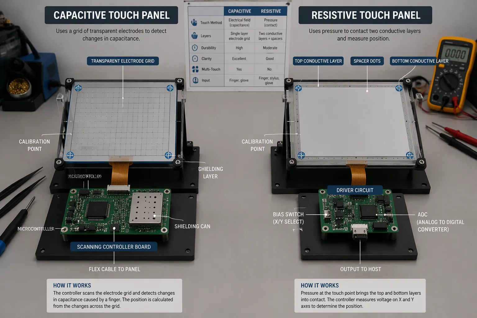
The touch driver sets the first real divide. A capacitive touch design needs a scanning front end, a stable reference, and firmware that maps a grid of weak signals to coordinates. A resistive touch panel needs a bias switch and an ADC path. The resistive path is simpler to build and easier to debug.
Calibration follows the same pattern. A pcap controller ships with factory tuning, yet you still manage noise thresholds and environmental drift. A resistive touch screen needs a simple two-point or four-point calibration at assembly. That step is quick, and it rarely repeats unless the panel deforms.
Accuracy and latency split the two camps as well. Mutual-capacitance sensing resolves each finger precisely and supports fast, smooth, multi-touch interaction. A resistive touch screen reports one contact point, and its settling delays add a small lag. Neither limit matters for a keypad. Both matter for a map or a drawing app.
Performance, Power, and Cost
Power favors resistive. A capacitive touch panel must scan continuously to catch an approaching finger, so its controller stays active. A resistive touch panel draws almost nothing until contact closes the gap. Battery products with long idle periods often prefer the resistive route.
Cost favors resistive at the low end. The panel is cheap, and the touch driver can be a few discrete parts plus an ADC channel you already own. A capacitive touch design needs a dedicated controller, a shield layer, and more layout care. That bill of materials grows with screen size.
Troca | Capacitivo | Resistivo |
|---|---|---|
Complexidade do motorista | High — scan engine, filtering, tuning | Low — bias switch plus ADC |
carga de calibração | Factory tuning plus noise management | Simple assembly calibration |
Multi-touch | Yes, with mutual sensing | No, single contact point |
Latência | Low with a fast scan | Slight settling delay |
Energia | Varredura contínua | Near zero when idle |
Custo da lista de materiais | Mais elevado | Abaixe |
The table shows why capacitive vs. resistive touch panels rarely compete on one axis alone. Pick the touch technology that matches your product’s priorities. A bright, responsive interface justifies the capacitive cost. A rugged handheld with a stylus and a tight budget justifies the resistive choice. Weigh the touch screen decision against your full system, not against a single spec sheet line.
Environment and OEM Selection
Gloves, Stylus, and Harsh Conditions
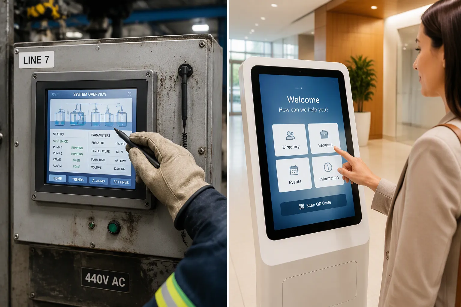
An OEM weighs cost, durability, glove use, and environment together before choosing a touch panel. The input method often decides the outcome. A capacitive touch screen accepts only conductive inputs, so a standard stylus or an insulating glove will not register.
Capacitive screens accept only conductive inputs (e.g., human fingers), limiting stylus use unless specially conductive. Performance is affected by water or gloves: water (conductive) may register as a touch, while gloves (insulating) prevent the gloved finger from acting as a conductor.
Manufacturers answer this limit with glove-friendly capacitive screens. These designs boost sensitivity or apply specialized firmware. A capacitive sensing study by Fischer et al. classified 50 finger touches, 25 glove touches, and 20 non-valid touches. An RNN classifier reached 97.1% de precisão geral even with gloves, which shows that advanced filtering can recover gloved input.
A resistive touch screen takes any input that applies pressure. A gloved hand, a plastic stylus, or a fingernail all work. That makes the resistive touch panel the safer pick for a cold warehouse or a factory floor. The trade-off is a higher false-touch risk on the capacitive side, where static, surface contamination, or a hovering finger can trigger a ghost touch.
Escolhendo por Aplicação
Match the technology to the use case. Consumer electronics and clean environments favor capacitive touchscreens. You get multi-touch, gesture recognition, optical clarity, and light-touch operation. A phone, a tablet, or a lobby kiosk fits this profile well.
Rugged and glove-heavy products favor resistive. Choose it when gloved operation is required, contamination is likely, EMI resistance is critical, or cost must stay low. A handheld scanner, a medical cart, or an industrial HMI fits here. The resistive touch screen also tolerates a stylus for precise data entry.
Aspecto | Resistivo | Capacitivo |
|---|---|---|
Gloved input | Universal input compatibility; responds reliably to gloved touch | Relies on skin conductivity; gloves act as insulator |
à Taxa de juros | Requer pressão | Lighter touch activation |
False-touch risk | Abaixe | Mais elevado |
Recomendado quando | Gloved operation, contamination, EMI, cost | Multi-touch, gestures, clarity, light touch |
Weigh noise, calibration, power, and environment as one set. A pcap design needs shielding and tuning. A resistive design needs calibration and wear planning. Let the application decide, not the spec sheet.
The sensing physics decides everything downstream. A touch panel that scans an electric field behaves nothing like one that waits for pressure. The pcap vs. resistive touch split shapes your driver, your bus, and your power budget. Weigh noise, calibration, power, and environment as one set.
Match the technology to the job. Choose capacitive for bright, responsive, multi-touch consumer interfaces. Choose resistive for low cost, high resolution, glove or stylus input, and rugged sites.
Hybrid designs now merge both effects in one flexible sensor. Hwang et al. report a device that detects touch and pressure together. Treat these as promising, not proven for every product.
Perguntas frequentes
Does a capacitive touch panel need pressure to register a touch?
No. A capacitive touch panel detects a small capacitance change when your finger nears the sensor. The shift is tiny, near 1 pF, so the controller filters and averages many samples. A resistive screen works the opposite way. It waits for your press to close the air gap between its two sheets.
Which technology supports multi-touch?
Mutual-capacitance sensing supports multi-touch. It drives one axis and senses the other, so it resolves each finger separately. Self-capacitance struggles with ghost points when two fingers touch at once. A resistive screen reports only a single contact point, so it cannot track gestures across the surface.
Can I use a stylus or gloves with these screens?
A resistive screen accepts any input that applies pressure, including a plastic stylus or a gloved hand. A capacitive screen needs a conductive input, so an insulating glove will not register. Glove-friendly capacitive designs boost sensitivity, and one study reached 97.1% accuracy with an RNN classifier.
How much calibration does each design need?
A resistive screen needs a simple two-point or four-point calibration at assembly. That step rarely repeats unless the panel deforms. A capacitive controller ships with factory tuning, yet you still manage noise thresholds and environmental drift over the product’s life.
Which design draws less power?
A resistive screen draws almost nothing until contact closes the gap. A capacitive screen must scan continuously to catch an approaching finger, so its controller stays active. Battery products with long idle periods often prefer the resistive route for this reason.