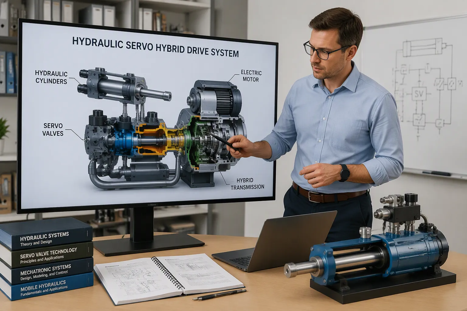
A hydraulic/servo hybrid drive system is a drivetrain that pairs servo-controlled hydraulic pump/motors with accumulators. The pump/motors drive the machine, and the accumulators store braking energy for later use. Its main job is to cut fuel consumption and raise efficiency through hydrostatic drive and regenerative braking. According to EPA data reported by STLE, such systems can recover 70% or more of braking energy that would otherwise be lost as heat. Five layers carry this function: the engine, the power drive unit, the pump/motors, the accumulators, and the electronic control board. Each layer shapes how a hydraulic/servo hybrid drive system delivers power and how its control electronics must be designed.
Основные выводы
Hybrid hydraulic systems save fuel and make brakes last longer by capturing energy when you brake.
Servo motors with constant pumps raise efficiency in every driving condition.
Accumulators save braking energy to use later, which cuts down on fuel use.
Хороший дизайн борта keeps high-power circuits and sensitive circuits apart. This helps prevent failures.
Check the accumulator pre-charge and dither settings often to keep the system working reliably.
Hydraulic/Servo Hybrid Drive System Architecture
Engine, Power Drive Unit, and Pump/Motors
The engine makes mechanical power. The power drive unit prepares that power and sends it to the pump/motors. A servo-controlled pump/motor changes mechanical energy into hydraulic energy, or the other way around. A high-pressure accumulator keeps fluid under pressure so it can be used later.
These parts take the place of the gearbox, torque converter, and mechanical shaft in a regular drivetrain. Power moves from the engine to the power drive unit, then to the pump/motors, and then to the wheels or implement. When the machine brakes, the flow goes the other way.
A servo-hydraulic drive package usually has a constant pump, a серводвигатель, and a converter with built-in servo-hydraulics software. The converter holds the pressure and flow control loops, so the package does not need a separate hydraulic control system cabinet.
Note: A servo motor uses power only when the machine needs it. A standard motor runs all the time and wastes energy in a traditional hydraulic circuit.
Accumulators and Energy Storage
A high-pressure accumulator is a sealed vessel that holds hydraulic fluid against a compressed gas charge. It works as a buffer between demand and supply. The gas charge sets the working pressure band.
The accumulator takes in flow spikes during acceleration and gives fluid back during peak load. This lets the engine run at a steadier operating point. Sizing depends on the pressure band and how much fluid the circuit must exchange per braking event.
Drive Package Configurations Compared
The table below compares three common configurations on energy efficiency.
Конфигурация системы | Энерго эффективность |
|---|---|
Standard motor + constant pump | Низкий |
Standard motor + variable pump | Средний |
Servo motor + constant pump | Высокий |
A variable displacement pump adjusts flow per revolution. A constant displacement pump with a built-in servo motor adjusts speed instead. The second approach keeps efficiency high across the duty cycle.
The package puts an actuator, servo motor, drive, controller, and software into one unit. Engineers should match displacement to the required flow at the target pressure. Do not oversize the pump, because too much displacement lowers part-load efficiency.
Hybrid Hydraulic and Servo Drive Technology Modes
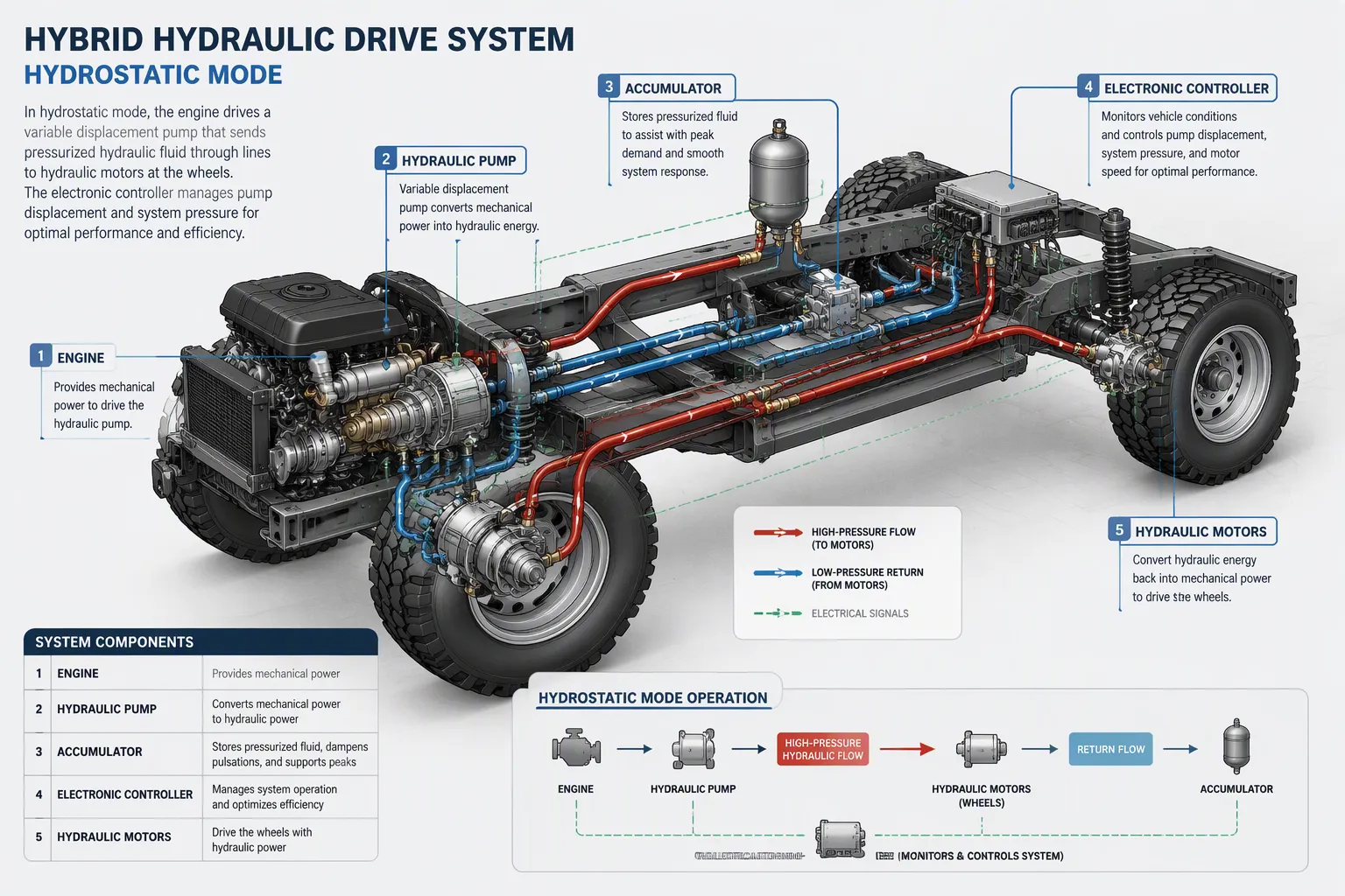
Hydrostatic Drive at Low Speeds
At low speed, the engine turns the pump, and the pump sends pressurized fluid to the pump/motors at the wheels. The machine moves using fluid power alone. An onboard controller coordinates pumps, hydrostatic motors, and accumulators to power the vehicle in hydrostatic mode. The system’s design improves efficiency by matching engine load with vehicle needs. It uses stored braking energy to power acceleration before switching to mechanical drive at highway speed.
This mode works well for stop-and-go driving. The engine keeps a steadier speed instead of surging with every start. Regenerative braking stays available the whole time, and the captured energy comes back on the next launch. The table below shows how speed range maps to drive mode.
Диапазон скоростей | Режим привода | Характеристики: |
|---|---|---|
0–25 мили в час | Two-speed hydrostatic drive (low speed) | Urban driving; brake energy recovery supported |
26–45 мили в час | Two-speed hydrostatic drive (high speed) | Hydrostatic operation continues; brake energy recovery supported |
45+ миль в час | Mechanical direct drive | Efficient high-speed operation; smooth automatic shifting; brake energy still recoverable because the primary pump stays connected to the drive shaft and acts as a pump, applying torque and charging the accumulator |
A two-gear hydrostatic layout lets the controller keep the pump and motor in an efficient band across the whole low-speed range.
Direct Mechanical Drive at High Speeds
Above the switch point, the drivetrain locks into a mechanical path. Engine power reaches the wheels with fewer conversion steps, so losses drop at highway speed. The shift happens automatically, and the driver feels no interruption. The primary pump stays coupled to the drive shaft. During deceleration it reverses its role, applies braking torque, and charges the accumulator, so energy recovery continues even in mechanical mode.
Kawasaki’s electro-hydraulic hybrid system shows how displacement control supports this split. A variable displacement pump switches between a large and a small setting. In the high-pressure state, the pump drops to the smaller displacement. Required torque falls, and the motor capacity can shrink accordingly. Matching displacement to pressure conditions keeps the package compact.
Switching Logic and Mode Selection
The controller decides the switch point from vehicle speed, pressure, and demand. Hysteresis around the threshold prevents hunting between modes. You should verify the transition under loaded and unloaded conditions before release.
Критерий | Hydrostatic Mode | Механический режим |
|---|---|---|
Диапазон скорости | От низкого до среднего | Высокий |
Восстановление энергии | Непрерывный | Continuous via connected pump |
Наилучшее использование | Циклы запуска-остановки | Спокойный крейсерский ход |
These modes bring extra gains. Noise stays low, heat generation drops, and the hydraulic circuit needs fewer valves. Together they support highly dynamic and highly accurate drives in hybrid hydraulic and servo drive technology.
Servo Hydraulic Actuators and Regenerative Braking
Capturing Kinetic Energy in Accumulators
When the machine brakes, servo hydraulic actuators switch to a different job. The controller tells the pump/motor to work as a pump. The machine’s momentum spins the shaft, and the unit pushes fluid into the high-pressure accumulator. By controlling the swashplate or valve setting precisely, the system can apply braking torque smoothly.
Electro-hydraulic servo actuators react in milliseconds, so the braking force follows the driver’s pedal or the controller’s demand. The accumulator charge goes up with braking power, which grows with total inertia and with the square of machine speed. Servo cylinders on lift or steering functions can recover energy in the same way.
Tip: Check the accumulator pre-charge pressure before every test run. A low gas charge reduces storage capacity and raises fluid temperature.
Reusing Stored Energy on Acceleration
On the next launch, stored pressure adds to engine power. The controller opens the accumulator path, and pressurized fluid drives the pump/motor or a hydraulic actuator directly. This boost lowers the torque the engine has to supply.
The hybrid linear actuator case shows the principle clearly. Braking energy from a machine axis feeds an on-board system, such as a lift or clamp circuit, instead of going back to the engine. Hybrid linear actuators therefore cut both fuel use and cycle time. Linear servo actuators with programmable position and force control apply the released pressure with precise force and speed control.
Comparing Energy Recovery Paths
The table below compares two recovery paths on response and circuit complexity.
Путь восстановления | Режимы секции мощности | Сложность схемы |
|---|---|---|
Accumulator storage | Быстро и прямо | Средняя |
Slower conversion chain | Высокая |
Accumulator storage works well for high-power, short-duration cycles. A servo motor driving a pump adds displacement flexibility, and variable displacement lets the controller match flow to demand. Pick the path that fits the duty cycle, then size the accumulator or storage bank to match.
Servo-Controlled Actuators: Board-Level Design and Manufacturing
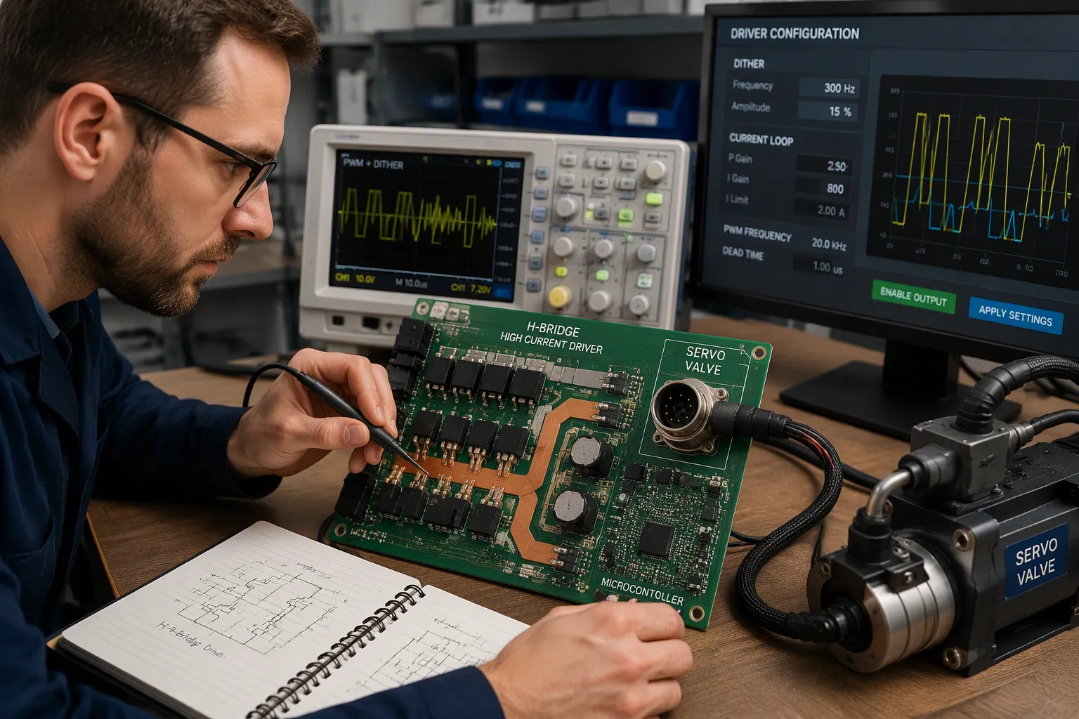
Driving Solenoids and Servo Valves with PWM Dither
A proportional solenoid turns coil current into force. Copper resistance goes up with temperature, so current and force drift unless the driver closes the loop. You should design the PWM stage with internal closed-loop current control. Figure out the maximum current draw at the hottest expected coil temperature and the lowest supply voltage, because heat rise cuts output.
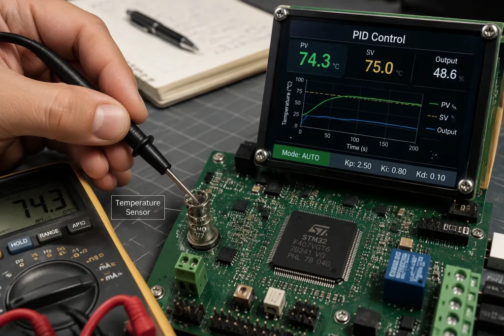
Dither keeps the spool moving at small commands. Static friction can stick the valve, and a tiny, unnoticeable vibration stops it. Valve-mounted drivers often come with dither frequency, amplitude, dead band, and input mode set at the factory. Universal drivers must offer these as adjustable settings. Stay away from rheostat-based coil control; it wastes power, makes heat, and gives no dither or current feedback, so hysteresis drifts outside published limits.
Pressure and flow transducers close the outer loop. Accept analog inputs from a PLC or controller, including 0-5 VDC, 0-10 VDC, and 4-20 mA. The current loop fights interference over long cable runs. Spool position feedback makes behavior steadier and supports dither from the driver.
Параметр | Проектное действие |
|---|---|
Dither frequency | Match to valve spec; expose as adjustable on universal drivers |
Dither amplitude | Keep unnoticeable; check for no spool overshoot |
Токовая петля | Close internally for repeatable force |
Режим ввода | Support voltage and 4-20 mA current inputs |
Tip: Check dither settings on the real valve, not just the datasheet. Small command signals show stiction first.
Mixed-Signal Partitioning, Protection, and DFM Trade-Offs
High-current solenoid drivers and precision servo drive circuits share one board, so split them by zone. Give the H-bridge wide copper, a direct return plane, and Kelvin shunt routing. Save a quiet ground area with dense decoupling for the MCU or FPGA. Route encoder differential pairs away from gate-drive edges and power vias. Put creepage slots and isolated DC-DC spacing at the safety barrier. Poor separation between switching loops and sensing circuits causes most failures.
Protection follows the same rule. Sense current at the shunt, add short-circuit limiting, and provide freewheeling and flyback paths for every inductive load. Plan power by adding simultaneous channel currents plus controller draw and margin. Work out voltage drop across source, protection, connector, copper, via, cable, and return, then confirm it by measuring at the loaded connector. Place bulk capacitors at the rail entry and at branches with fast load steps.
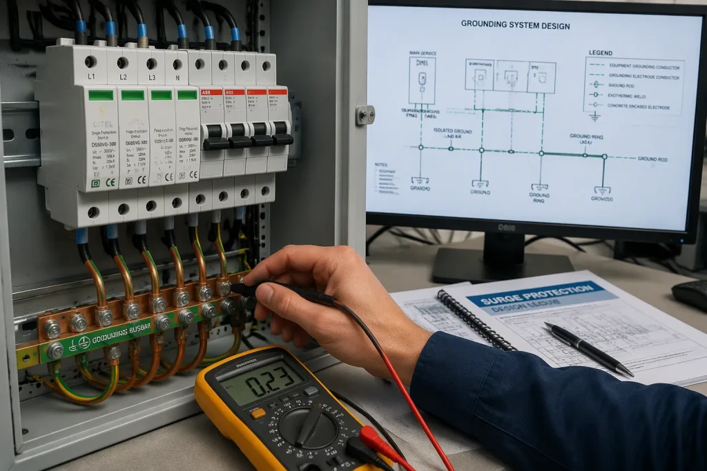
Isolation between the hydraulic side and control logic protects both. Match reverse-polarity, surge, and overcurrent protection to source energy and likely harness faults. For DFM, pick copper weight and stackup from current, temperature rise, and routing density, then confirm spacing and via rules with the fabricator.
Note: Shared connector pins and thin ground traces shift the local logic reference through transient current, causing resets.
Thermal Design and Fault Verification
Tie exposed pads to continuous copper with a thermal-via pattern, then measure the assembled board under the worst likely motion profile. Log input voltage, active channels, mechanical load, airflow, enclosure state, ambient temperature, and soak time beside every result. Compare hot spots against device limits and the derating policy. Check per-channel current ratings; some multi-channel boards deliver far less total current than the channel count suggests. Boards rated for 24 V should include reverse-polarity protection and thermal shutdown.
When a fault appears, reproduce it with the exact joint combination, acceleration, and load. Measure minimum rail voltage and transient duration at local test points with enough bandwidth. Correlate supply voltage, reset, command signal, and fault output on one time base. Isolate causes by testing one actuator at a time and rerouting cables. Re-run the worst-case motion across intended input-voltage and temperature conditions to confirm the fix.
Benefits, Limitations, and Market Context
Fuel Savings, Brake Life, and Maintenance
Real-world numbers from garbage truck fleets show how big the gains can be. City of Miami officials report 51% fuel savings with the Parker RunWise system, and Miami-Dade County officials report 45%. This same system saves 20–30 gallons of fuel per day, depending on route density and how much the truck is used. Parker claims about 50% savings across different applications.
Brake life gets much better too. Most garbage trucks need new brakes 3–4 times a year. City of Miami fleet records show brakes that lasted over 6 years without being touched. Jose Davilla, superintendent for the City of Miami, says brake maintenance savings reach $81,000 by the 6-year mark of a 10-year vehicle lifecycle.
Метрика | Значение |
|---|---|
Fuel savings, City of Miami | 51% |
Fuel savings, Miami-Dade County | 45% |
Brake maintenance savings, 6-year point | $81,000 |
Baseline brake replacement | 3–4 раза в год |
Brake service interval achieved | Over 6 years, untouched |
Hybrid electro-hydraulic actuators also beat traditional hydraulic power systems in several ways. A power-on-demand design uses energy more efficiently than a motor that runs all the time. Onboard servo control gives precise control of position, speed, and force. A fully sealed, closed-circuit system needs no fluid refills, and a built-in filter rated above 8,000 hours supports maintenance-free operation. These units handle shock loads and side loading, and they reach force capability up to 150,000 lbs (667 kN).
Tip: Compare maintenance intervals, not just purchase price, when you evaluate hybrid drive solutions.
Competition and Fuel-Agnostic Capabilities
Electric power competes directly in some machine classes. Battery cost, charging infrastructure, and duty-cycle fit decide who wins. Hydraulic systems hold an advantage in high-force, high-shock applications, where a hybrid linear actuator delivers 300% higher power density than a comparably sized electromagnetic actuator.
Running on any fuel is a core strength. The engine layer accepts diesel, natural gas, or other fuels without redesigning the hydraulic circuit. A hybrid linear actuator and other hybrid linear actuators recover braking energy no matter which fuel is burned. Two displacement settings on the pump keep the package compact across pressure conditions. Engineers should weigh duty cycle and infrastructure before choosing between electro-hydraulic and battery-electric paths.
Limitations and Design Constraints
Accumulator sizing limits how much energy the system stores per braking event. A low gas pre-charge cuts capacity and raises fluid temperature. Packaging also limits the design, because high-pressure vessels need space and structural protection.
Control complexity goes up with mode switching. The controller must manage hysteresis, pressure bands, and fault response across the whole drive. You should verify transition behavior under loaded and unloaded conditions before release.
The design allows two ways to drive the machine. These modes, plus regenerative braking, create the fuel and maintenance savings. The control board makes that ability into motion that is precise and repeatable.
For engineers, the hydraulic/servo hybrid drive system gives a drivetrain that runs on any fuel and is easy to maintain. Its electronics layer still needs careful mixed-signal partitioning and thermal design. Treat these two areas as top priorities, not things to think about later.
Stricter emissions rules favor drivetrains that burn less fuel and recover braking energy. Teams that learn both the hydraulic and electronic layers will find the platform fits that direction well. Careful design work here pays off over the life of the machine.
FAQ
How should you check accumulator pre-charge before a test run?
Check the gas charge against the specified pressure band before every run. A low charge cuts storage capacity and makes the fluid hotter. Read the value on the hydraulic circuit, then write it down next to the test conditions. Do the check again after any service that opens the vessel.
Why does a proportional solenoid driver need PWM dither?
Static friction can make the valve spool stick at small commands. A tiny vibration you can’t notice keeps the spool moving. Set dither frequency and amplitude to the valve spec, and make both adjustable on universal drivers. Check the settings on the real valve, not just the datasheet.
How do you partition high-current solenoid drivers and precision servo circuits on one board?
Split the board into zones. Give the H-bridge wide copper, a direct return plane, and Kelvin shunt routing. Keep a quiet ground area with dense decoupling for the controller. Route encoder differential pairs away from gate-drive edges. Most failures come from poor separation between switching loops and sensing circuits.
What should you verify before releasing a mode-switching drive?
Test the transition with the drive loaded and unloaded. Confirm that hysteresis around the switch point stops hunting between modes. Line up supply voltage, reset, command signal, and fault output on one time base. Re-run the worst-case motion across the planned input-voltage and temperature conditions before release.