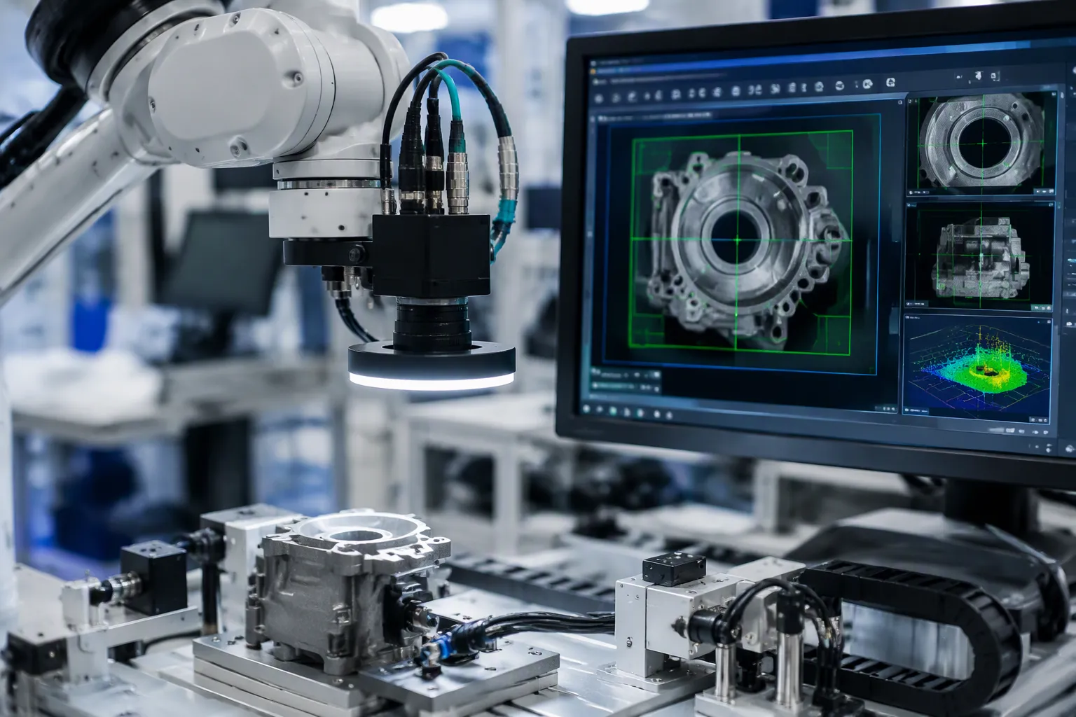
Vision recognition and robotic arm teamwork runs in a closed loop. Cameras watch the workspace, and the perception pipeline finds each object and its pose. Visual servoing then guides the arm in real time. The main parts are the camera or cameras, the perception pipeline, pose estimation, the motion planner, and the controller. This loop matters to hardware engineers and electronics product teams because board-level design decides its success. Interface choice, latency, noise, and manufacturing trade-offs set the real limits. The payoff is closed-loop accuracy, adaptability to changing part positions, and reduced fixturing. Analysts value this market at USD 3.89 billion in 2025, with an 11.2% CAGR from 2027 to 2035. You will see how machine vision, computer vision, and vision integration connect the robot and the vision system. Robotic arms reward careful design, and robotic arms punish shortcuts.
चाबी छीन लेना
Vision and robotic arms work together in a loop: cameras spot objects, and the arm moves to them.
Pick your camera interfaces by how long the cable is: MIPI CSI-2 for short runs, USB3 for a few meters, and GigE for long distances.
Check and adjust hand-eye coordination often to stop drift and keep accuracy.
Plan the time budget from when the camera takes a picture to when the arm moves, so you avoid delays.
Keep motor noise away from camera cables so the image stays clear.
Robotic Arm Fundamentals and Machine Vision Control
Six Degrees of Freedom and Arm Kinematics
A six-axis jointed robotic arm places its tool in three translational and three rotational degrees of freedom. Forward kinematics works out the end-effector pose from the joint variables. You link the transforms from the base frame to the tool frame. Under the Denavit-Hartenberg convention, each joint has four parameters: link length, link twist, link offset, and joint angle. Multiplying the per-joint homogeneous matrices gives the base-to-tool transform. Its top-left 3×3 block is the rotation matrix, and the first three elements of the fourth column give the position vector.
Inverse kinematics goes the other way. It solves for joint angles when you know the desired pose. Closed-form solutions are rare and mostly exist for arms with spherical wrists. So most robotic arms use numerical iteration:
Begin with an initial joint guess.
Compute the current pose through forward kinematics.
Compute the pose error.
Update the joints using the Jacobian pseudoinverse scaled by a step size.
Repeat until the error falls below tolerance.
The Perception-to-Action Control Loop
The loop closes in five stages: frame capture, detection, pose estimation, planning, and control. Machine vision supplies the raw frames. Computer vision and vision recognition turn those frames into object identities and 6-DoF poses. The planner turns each pose into a joint trajectory, and the controller drives the robotic arm along it. Every stage adds delay, so timestamp frames at capture and budget latency end to end.
Vision integration often puts integrated cameras right on the end-effector. This eye-in-hand layout removes blind spots near the gripper and makes calibration simpler. Multi-camera views extend perception to the full 3D workspace, which helps complex manipulation and precise manipulation of parts in cluttered bins. The same architecture scales from industrial and collaborative robots to collaborative robotics cells, where a second articulated robotic arm tracks moving objects. Designers of robotic arms should treat camera placement as a mechanical decision, because mounting stiffness affects pose accuracy as much as the algorithm does.
Computer Vision and Object Recognition Techniques

PBVS, IBVS, and Hybrid Visual Servoing
Position-based visual servoing (PBVS) uses machine vision to find where the part is in 3D space. Then it tells the robotic arm where to move in Cartesian space. Image-based visual servoing (IBVS) skips that step and moves the robotic arm straight from image features. Hybrid schemes run both loops at the same time.
Hybrid 2 1/2-D schemes balance the local stability of IBVS against how much PBVS depends on accurate pose estimation, calibration, and object models.
दृष्टिकोण
Robustness characteristics
जटिलता
Hybrid (IBVS + PBVS)
Handles feature occlusion and makes up for pose errors from odometry or slippage
Higher: two loops to design and tune
आईबीवीएस
Depends on visual feedback, not internal odometry
Lower: single loop
PBVS
Needs accurate pose estimation, calibration, and object models
Lower: single loop
Pick PBVS when you have a clean CAD model and a well-calibrated cell. Pick IBVS when calibration drifts or the part has no texture. Most robotic arms in production run one loop. Most robotic arms in research labs run hybrid. Save hybrid designs for complex manipulation, where occlusion is common. Robotic arms that face shiny parts also gain from the extra feedback.
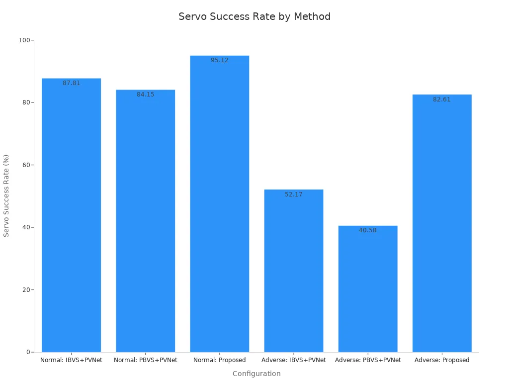
Published trials on textureless objects show the gap. A keypoint-based EKF method reached a 95.12% servo success rate under normal conditions and 82.61% under adverse conditions. The IBVS+PVNet baseline reached 87.81% and 52.17%. The PBVS+PVNet baseline reached 84.15% and 40.58%. The same method posted the lowest translation error, rotation error, and trajectory length ratio in both scenarios.
Deep Learning for Detection and Pose Estimation
Deep learning now does most of the object recognition work in vision recognition pipelines. Modern estimators predict object width and angle directly. That output gives the robotic arm a grasp pose without a CAD model.
MegaPose: a render-and-compare pipeline with strong zero-shot performance through coarse-to-fine refinement.
FoundationPose: a unified framework for detection, tracking, and pose estimation on novel objects.
Both run on the YCB-Video test set. The source reports no accuracy figures for them there. On a newer 6-DoF grasping dataset, EfficientPose reached 97.05% and FFB6D reached 98.09%.
आदर्श | Reported accuracy |
|---|---|
EfficientPose | 97.05% तक |
FFB6D | 98.09% तक |
Benchmarks such as the BOP challenge pushed this progress. They score methods with geometric metrics like ADD and MSSD.
Vision-language models and IBVS are still emerging control directions. Treat them as promising, not proven. Many teams pair classical servoing with ai models for detection. That split keeps the control loop predictable. Artificial intelligence helps most at the perception stage, where computer vision and object recognition handle clutter. Artificial intelligence adds less value inside the servo loop today. मशीन दृष्टि vendors now ship ai models on board, and computer vision libraries cover the rest. Robotic arms in logistics cells still need a fast, simple servo law. Pattern recognition alone will not close the loop. A second robotic arm can track a moving target, and that setup rewards tight timing over model size.
Vision Integration for Vision-Guided Arms
Camera Interfaces, Calibration, and Hand-Eye Coordination
RSI कैमरा इंटरफ़ेस you pick sets how far your robotic arm cell can reach and how precise it can be. MIPI CSI-2 works well for short board-to-board runs inside the arm housing. USB3 handles a few meters with simple cabling. GigE reaches far across a production line, but it adds packet jitter that you must plan for. Choose the interface based on cable length first, then on resolution and frame rate.
Route high-speed differential pairs with symmetry. Keep P and N traces on identical paths with balanced bends and vias. Hold spacing constant from transmitter to receiver, and match P and N lengths to cut skew. Route pairs over a continuous ground plane, and avoid split planes and copper cutouts. For USB 3.0 and similar links, keep skew within 25–50 ps and hold differential impedance near 90 Ω ± 10%. Place AC coupling capacitors symmetrically, and prefer small packages such as 0402.
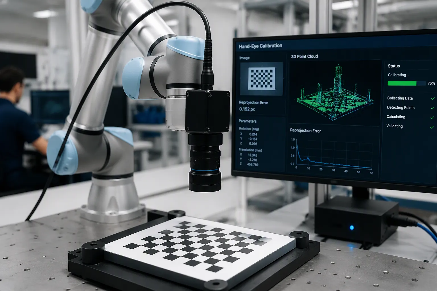
Hand-eye calibration estimates the transform between the end-effector and the camera frame. The standard form is AX = XB, where A and B are arm and camera poses between frames and X is the unknown transform. You can use the calibration plate method, which takes at least ten images of a plate mounted on the robotic arm. The point pair list method works without a plate on the work object. Automatic calibration routines now run these steps with little operator input. Typical results across six joint configurations are shown below.
मैट्रिक | अनुवाद करें | रोटेशन |
|---|---|---|
Max RV (X, Y, Z) | 2.471 मिमी, 3.751 मिमी, 1.423 मिमी | 0.957 °, 0.454 °, 0.702 ° |
Average RV | 2.548 मिमी | 0.704 ° |
Average deviation (SD) | 0.930 मिमी | 0.265 ° |
Validate with a static test on a table and a dynamic test that registers transformed point clouds through ICP.
Latency Budgeting and Noise Isolation
Plan your latency budget from frame capture to arm motion. Timestamp every frame at capture, then add detection, pose estimation, planning, and bus delay. EtherCAT gives deterministic timing for the robotic arm controller.
प्राचल | Typical EtherCAT Performance |
|---|---|
Cycle time (10 servo axes) | 100–250 µs |
घबराना | <1 μs |
Distributed-clock sync accuracy | better than 100 ns |
Distributed Clocks keep every slave aligned in hardware, so timing holds under software load. CAN remains fine for slower axes on smaller robotic arms.
Keep motor driver noise away from the image chain. Bond cable shields 360° at both ends, and never land a shield through a pigtail drain wire. Separate signal and power routing inside the cabinet. Slow MOSFET gate drive and shrink high-current loop areas to cut emissions at the source. These steps protect machine vision accuracy during manipulation tasks.
For DFM, confirm the stackup before routing, keep trace geometry within ±5 mil, and agree on impedance tolerances with your fabricator. Machine vision integration succeeds when board layout, calibration, and timing all get equal attention. Vision integration fails when any one of them is treated as an afterthought. Plan vision integration early, and your robotic arms will hold accuracy across the line.
Applications, Challenges, and Machine Vision Solutions
Real-World Use Cases in Manufacturing and Logistics
Vision-guided collaborative robots show up in pick-and-place cells, bin emptying, and finding objects on a production line. A 3D camera can see features smaller than 5 mm, so a robotic arm can clear a packed bin without grabbing the wrong part. Dual-arm cobots follow moving objects, and human-robot cells pass parts between a person and an arm. Vision integration pays off in ways you can measure:
Picking speed tops 200 items per hour, with accuracy above 99.9% and placement precision near ±0.1 mm.
Sorting accuracy goes up by nearly 25%–30%, and peak-hour fulfillment speed rises a lot.
Error rates drop, and you can move workers to tasks that add more value.
These results support efficiency, repeatability, and safety across industrial and collaborative robots. Vision-guided cobots also support remote operation and data collection, which feeds robotic machine learning data pipelines. That same ai data collection loop trains ai models for complex manipulation. Expect ai-powered arms to rely on imitation learning and remote operation before they handle complex manipulation on their own.
सामान्य विफलता के तरीके और निवारण रणनीतियाँ
Latency, calibration drift, reflections, occlusion, and motor noise leaking into the image chain cause most failures. Recognition and path planning take 100–500 ms per cycle, and that delay alone breaks tight servo loops. Typical industrial grasping failure rates run 2–8% per hour, and ordinary pick-and-place drop rates run 3–5% per hour. Hard shapes push peak drop rates to 10–12% per hour, against a target below 0.1% per hour.
रोग की स्थिति | Effect on failure rate |
|---|---|
Vibration above 0.5g or temperature swing above 15°C per cycle | 200–300% अधिक |
Inconsistent illumination | 40–60% higher depth error |
You should fix these at the board level. Shield the image chain, bond shields 360°, and keep motor power lines apart from camera rails. Add environmental compensation and predictive maintenance with vibration and thermal sensing. Machine vision with ai models predicts grip failures in real time. Computer vision handles detection, and vision-based manipulation tasks gain from adaptive grip force control. Keep calibration routines on a schedule, and treat vision-guided manipulation as a timing problem first.
You now have a simple picture of the loop. Cameras take in the scene, vision recognition turns pixels into object poses, and the controller moves the robotic arm along a planned path. Feedback closes the circle every cycle.
Think about your trade-offs early. Classical servoing stays predictable and cheap to check. Deep-learning methods give you adaptability, but they cost data and compute. Interface reach, latency budget, and noise isolation pull against each other, so set your priorities before layout.
Keep an eye on learned visual servoing, vision-language models, and event cameras. Vision-guided cobots will gain from teleoperation and data collection, and ai models will push complex manipulation further. Artificial intelligence will not replace your timing budget. Start with one calibrated cell, log every cycle, and let collaborative robotics grow from there. Robotic arms reward discipline. Robotic arms built on measured data handle complex manipulation with confidence.
सामान्य प्रश्न
Which camera interface should you choose for a robotic arm cell?
Start with cable length. MIPI CSI-2 suits short board-to-board runs inside the arm housing. USB3 covers a few meters with simple cabling. GigE reaches across a production line, but you must plan for packet jitter. Match the interface to your reach first, then to resolution and frame rate.
How do you keep motor noise out of the image chain?
Bond cable shields 360° at both ends. Never land a shield through a pigtail drain wire. Separate signal and power routing inside the cabinet. Slow the MOSFET gate drive and shrink high-current loop areas. These steps protect machine vision accuracy when a robotic arm moves fast near the camera.
Why does calibration drift break a robotic arm over time?
Thermal swings and vibration shift the hand-eye transform. A robotic arm then grasps with a growing offset. Keep calibration routines on a schedule. Add vibration and thermal sensing for predictive maintenance. Validate with a static table test and a dynamic point-cloud test through ICP.
When should you pick classical servoing over deep learning?
Pick classical servoing when the cell is well calibrated and the part has texture. A robotic arm then runs a predictable, checkable loop. Choose deep-learning pose estimation for clutter, novel objects, or shiny parts. Many teams split the work: ai models detect, and a simple servo law drives the robotic arm.