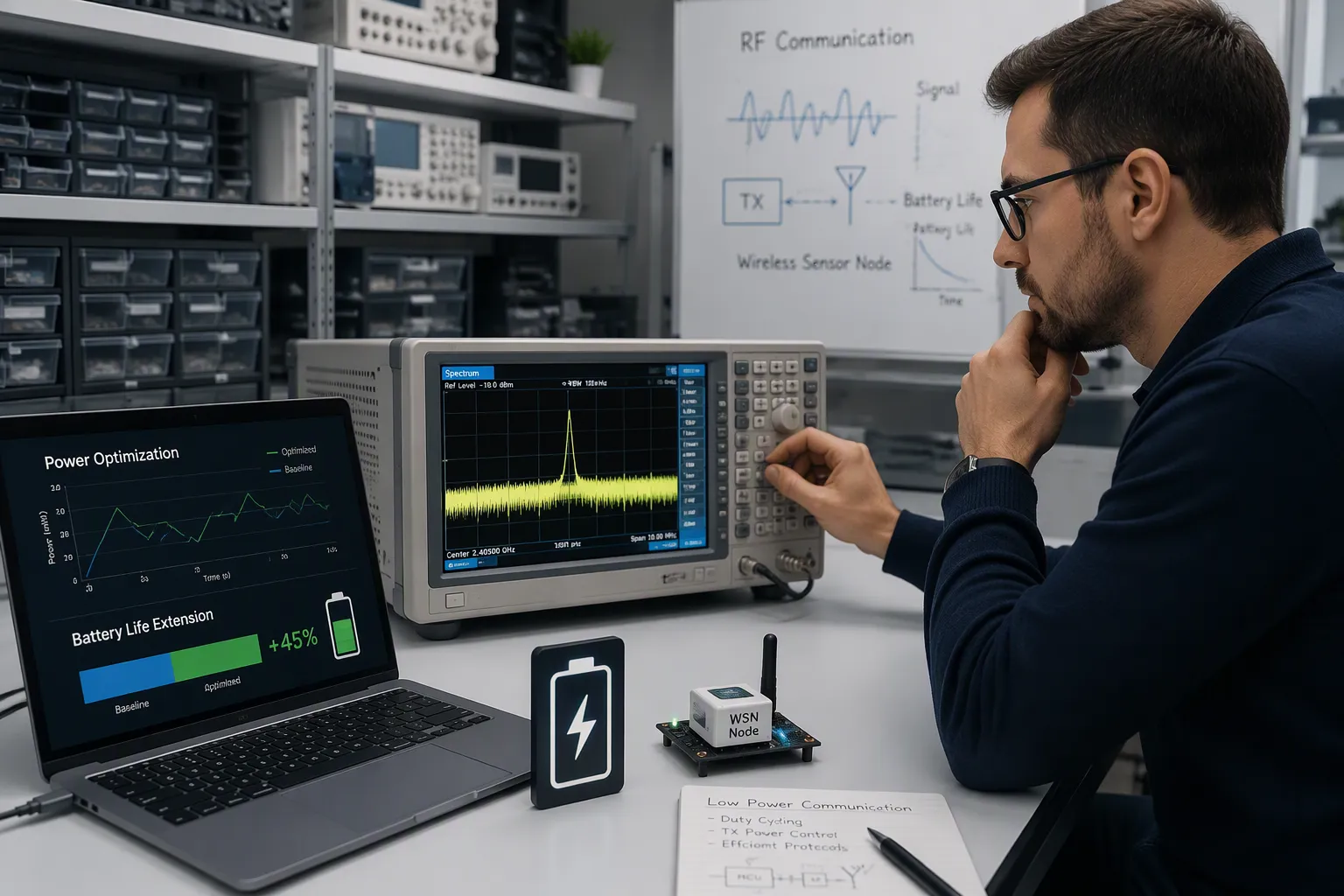
You can’t treat RF communication and power optimization as separate problems. Board-level design ties them together, and that link decides the battery life of every wireless product. This guide is for hardware engineers and electronics product teams building battery-powered RF devices. How do RF front-end choices and power techniques work together to set real runtime? You will see link budget, receiver sensitivity, board-level power factors, Bluetooth Low Energy tuning, and DFM trade-offs. Think about a BLE sensor node. Its radio draws the most current. Careful Bluetooth LE scheduling and sleep modes make it last longer. These choices give long battery life without extra cells.
चाबी छीन लेना
A bigger link budget lets you use less transmit power and still reach the receiver.
मिलाओ रिसीवर संवेदनशीलता to your real link margin so you don’t waste battery power.
मजबूत बनाए रखें जमीन विमान and put decoupling capacitors near RF chips to reduce power loss.
Pick the longest BLE connection interval that still works for you, so you save the most power.
Use RF energy harvesting with burst transmissions to cut down on or get rid of battery changes.
RF Communication Basics for Battery-Powered Designs
Link Budget and Path Loss
Link budget shows how much signal loss your rf communication link can handle. A bigger budget means you can send at lower power and still reach the receiver. Take the nRF52840 at +8 dBm and 1 Mbps. It gives an 89 dB लिंक बजट and about 280 m of theoretical range. Go down to 0 dBm and the budget drops to 81 dB, with about 110 m of range. Coded PHY raises the budget to 96 dB and stretches range to about 630 m.
Indoor spaces make these numbers much worse. Add 20–30 dB of path loss compared to free-space estimates. The 280 m outdoor figure falls to about 30–50 m indoors with a few walls. A human body in the path adds 3–6 dB. Drywall adds 3–5 dB per wall, and concrete or brick adds 10–20 dB. A plastic enclosure costs 1–3 dB. You can make up for these losses with dynamic transmission power adjustment. Raise power only when the link needs it, and keep average power consumption low.
Receiver Sensitivity and Current Draw
Receiver sensitivity and current draw work against each other. A more sensitive receiver catches weaker signals, so the transmitter can save energy. That sensitivity often costs more current consumption in the receive chain. You must weigh both sides against total power consumption.
Higher current draw in the receiver raises average power consumption across the duty cycle. For low power consumption, match sensitivity to the real link margin. A tight link budget leaves little room for a deaf receiver. A generous budget lets you accept lower sensitivity and lower current consumption. This balance supports low-power wireless communication and extends battery life. Every milliamp you remove from the receive path improves the life of the product.
Board-Level Power Consumption in RF Front-Ends
RF modules usually use the most power in a battery-powered device. RF communication needs clean power delivery. Board-level choices decide how much energy reaches the antenna and how much turns into heat. You can measure power consumption at the rail and compare it with the radiated output. That gap shows where power optimization pays off.
Layout, Grounding, and Shielding
A solid, continuous copper ground plane works better than a grid for RF boards. Grids can raise inductance by an order of magnitude at high frequencies. Pour ground on all non-signal layers and stitch it densely with through-vias. The RF return current follows the lowest-inductance path right beneath the signal trace. A split under that trace makes the loop area bigger and causes radiation, crosstalk, and loss, which raises current draw. One 5G mmWave module showed 10 dB सम्मिलन हानि from split grounds. A redesign with contiguous inner planes and λ/20 via stitching brought back a flat response to 28 GHz.
Place ground vias every quarter-wavelength along bends. Keep via aspect ratio near 0.8–1.2 for RF PCBs. Higher ratios raise inductance and hurt signal performance. These practices cut current consumption in the transmit path, lower power consumption, and protect battery life. They extend product life in the field.
DC-DC Placement and Decoupling
Power rail noise wastes energy, raises current draw, and lifts current consumption. Place a small ceramic capacitor tight to every RF IC supply pin. Add a mid-value capacitor and, for power amplifiers, bulk capacitance on the same layer. Give each capacitor its own dedicated ground via. Shared vias spoil the low-impedance decoupling path. Add LC filters and damping to buck converters. This stops peaking at switching harmonics that fall into RF bands. Place LDOs after buck converters to create low-noise rails for PLLs, LOs, and LNAs. Keep switch nodes away from antennas and feeds.
These steps lower average power consumption and current consumption across the duty cycle. They also minimize power consumption during idle states. You can then measure power consumption per rail and confirm the gain. Good decoupling supports low power consumption and longer life.
Bluetooth LE Power Consumption and BLE Power Efficiency
How much power Bluetooth LE uses depends on how often the radio wakes up and how long it stays on. You control both of these with Bluetooth low energy settings. When you tune them well, BLE devices get better battery life without any hardware changes.
Connection Intervals and Advertising Parameters
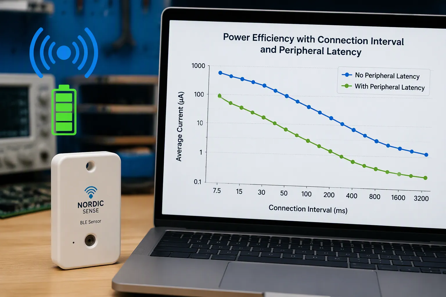
The connection interval sets how often the central and peripheral swap data. You can pick a value from 7.5 ms up to 4 s, in steps of 1.25 ms. A short interval means lower latency and higher throughput, but it also pulls more current. A long interval saves energy but adds latency. Peripheral latency lets the peripheral skip connection events when it has no data to send. The supervision timeout, from 100 ms to 32 s in steps of 10 ms, sets the longest the link can go without a packet before it drops.
Connection Interval | Peripheral Latency | Average Current (0 dBm TX) |
|---|---|---|
30 एमएस | 0 | ~228 µA |
75 एमएस | 0 | ~230 µA |
75 एमएस | 5 | ~140 µA (≈40% saving) |
875-950 एमएस | 0 | ~25 µA |
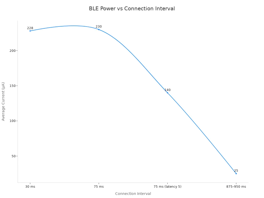
The data shows the payoff clearly. Stretching the interval from 30 ms to about 950 ms drops average current from ~228 µA to ~25 µA. Adding a peripheral latency of 5 at a 75 ms interval cuts current from ~230 µA to ~140 µA. An adaptive connection interval lets you switch between these settings as traffic changes.
Pick the longest connection interval that still meets your application’s latency and throughput needs, so power consumption stays as low as it can be.
The advertising interval matters just as much before a link exists. A longer advertising interval lowers Bluetooth LE power consumption during discovery. Short advertising bursts draw about 3 mA से 10 mA, while an active connection averages 5 mA to 30 mA over time. Idle sleep sits near 1 µA to 10 µA. These states set the lowest level of Bluetooth low energy power consumption in your product.
स्लीप मोड और ड्यूटी साइक्लिंग
Sleep scheduling is where you win BLE power efficiency. When set up well, the Silicon Labs Bluetooth stack puts the device into Deep Sleep mode and wakes it only for communication windows or pending tasks. Deeper sleep modes save more energy than lighter ones, so choose the deepest mode that still meets your wake-up needs.
Cutting radio frequency active time is the most direct lever you have. Fewer transmissions mean less current draw across the duty cycle. Keeping radio activity time short through duty cycling makes RF active time brief and predictable. You can then minimize power consumption in idle states and hold low power consumption through long standby periods. Optimizing Bluetooth low energy power consumption this way protects battery life and extends product life in the field. Good BLE power efficiency comes from scheduling, not from a bigger cell.
Board Design to Optimize Battery Life
Stackup, Thermal, and DFM Constraints
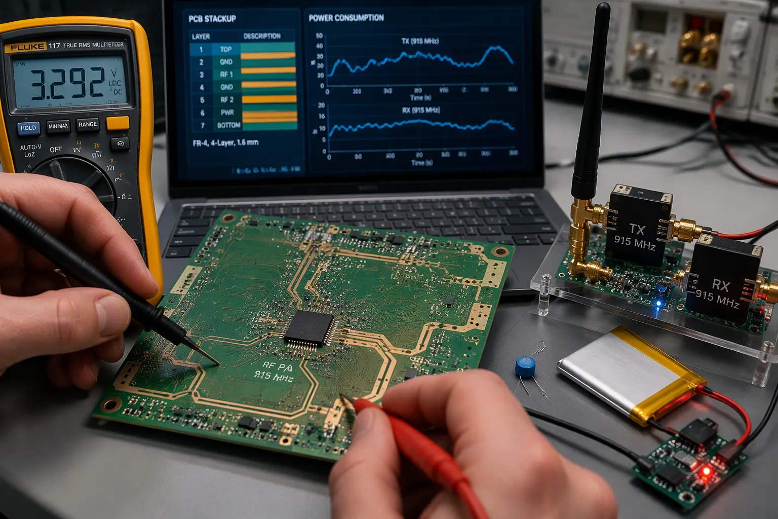
The layers you choose and the materials you use affect how much RF energy gets to the antenna. For battery-powered IoT nodes, every milliwatt used to send a signal shortens how long the device runs and adds to upkeep costs. Low-loss Rogers laminates let more RF energy leave through the antenna instead of turning into heat in the board material. Since this boosts efficiency, you can lower transmit power and still keep a good link, which greatly extends battery life. Check power consumption numbers early in the design cycle by using single PCB prototype services.
Thermal design matters too. A power amplifier that gets hot wastes energy and its performance drifts. Give the RF front-end copper pours and thermal vias to spread the heat. Keep temperature-sensitive references away from the PA.
DFM limits force trade-offs. Tighter trace widths and spacing raise cost and lower yield. Panel use and layer count affect price. Pick controlled impedance on the RF layers and check the stackup with your fabricator before release. These choices protect current consumption and support कम बिजली की खपत उत्पाद के जीवनकाल में.
RF Energy Harvesting and System Scheduling
RF harvesting can remove or shrink the battery in some designs. A 915 MHz RF transmitter sends out energy, and a receiver collects it. The collected RF energy is converted and stored in a capacitor. That capacitor gives a pulsed regulated voltage output to trickle charge energy storage devices. These include paper-thin long-life THINERGY MECs, other thin-film batteries, and regular rechargeable batteries. Built into micro-power devices like wireless sensors, the receiver can charge batteries from more than 40 feet away from the transmitter.
“Combining our THINERGY rechargeable MECs with Powercast’s RF energy harvesting system enables autonomous, self-powered, wireless systems for decades of maintenance-free operation,” says Tim Bradow, vice president of marketing for Infinite Power Solutions.
Pair harvesting with an ultra-low power consumption microcontroller. Schedule RF transmissions in bursts and let the MCU sleep between them. This approach supports low-power wireless communication and keeps average power consumption low. BLE links gain the most when you line up connection events with harvested energy windows. Fewer transmissions lower current consumption and extend life in the field.
तकनीक | Battery-Life Benefit |
|---|---|
Low-loss laminate | Less transmit power for the same link |
Thermal vias under PA | Stable performance, less wasted energy |
आरएफ हार्वेस्टिंग | Reduced or no battery replacement |
Burst scheduling | Lower average power consumption |
RF communication and power optimization belong together at the board level. Link budget, receiver sensitivity, board power factors, and BLE settings shape runtime. Bluetooth low energy tuning cannot save a noisy board. Apply these guidelines within DFM limits. That discipline delivers long battery life. It also lowers बिजली की खपत overall. Watch power consumption at each rail. Track power consumption across the duty cycle. Compare power consumption before and after changes. Measure power consumption in idle states. Bluetooth LE and BLE designs reward this. BLE products with tight scheduling last longer. BLE links with clean power waste less. Holistic board design will define future wireless products. That approach protects battery life in the field.
सामान्य प्रश्न
How much link budget do you need for an indoor BLE product?
Start with the radio’s budget and subtract real losses. Indoor spaces add 20–30 dB over free-space estimates. Drywall costs 3–5 dB per wall, and concrete or brick costs 10–20 dB. A body in the path adds 3–6 dB. Size your margin against these numbers, not the datasheet range.
Does a more sensitive receiver always save battery power?
No. Higher sensitivity usually pulls more current in the receive chain. Match sensitivity to your actual link margin. A generous budget lets you accept lower sensitivity and lower current draw. A tight budget leaves little room for a deaf receiver.
Which BLE setting saves the most power?
The connection interval gives the biggest gain. Stretching it from 30 ms to about 950 ms drops average current from roughly 228 µA to about 25 µA. Peripheral latency helps too. A latency of 5 at a 75 ms interval cuts current from about 230 µA to about 140 µA.
Why does a split ground plane hurt battery life?
Return current follows the path of lowest inductance, right beneath the signal trace. A split under that trace enlarges the loop area. Radiation, crosstalk, and loss rise, and current draw climbs with them. One 5G mmWave module lost 10 dB to split grounds.
Can RF energy harvesting replace the battery entirely?
Sometimes. A 915 MHz harvesting receiver can charge storage from more than 40 feet away. Pair it with an ultra-low-power माइक्रोकंट्रोलर and burst transmissions. Line up connection events with harvested energy windows. Many designs still keep a small cell as backup.