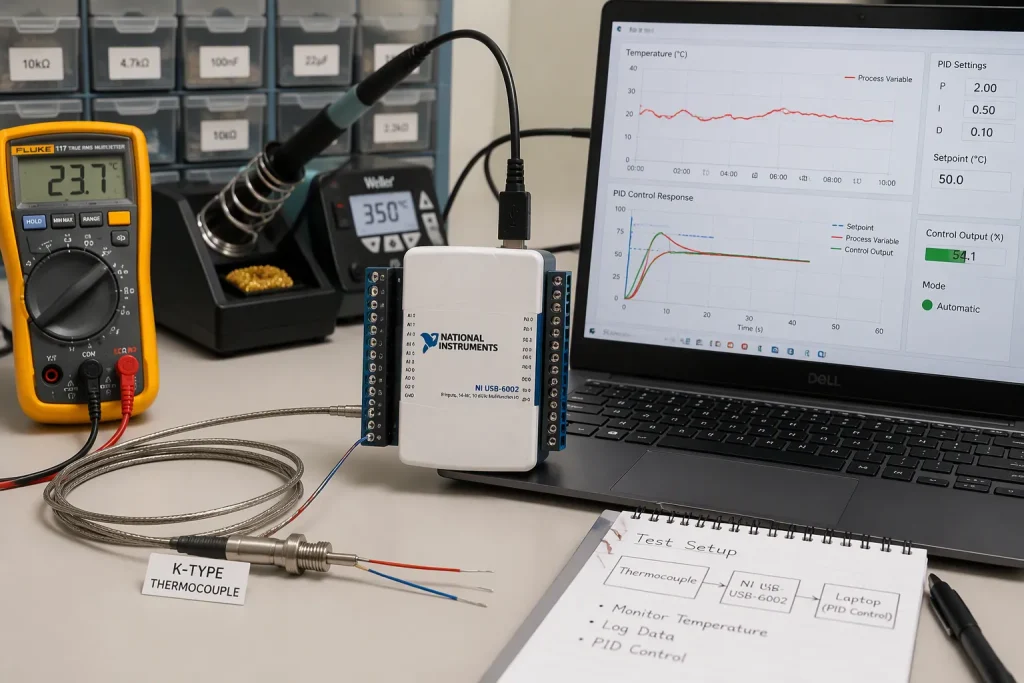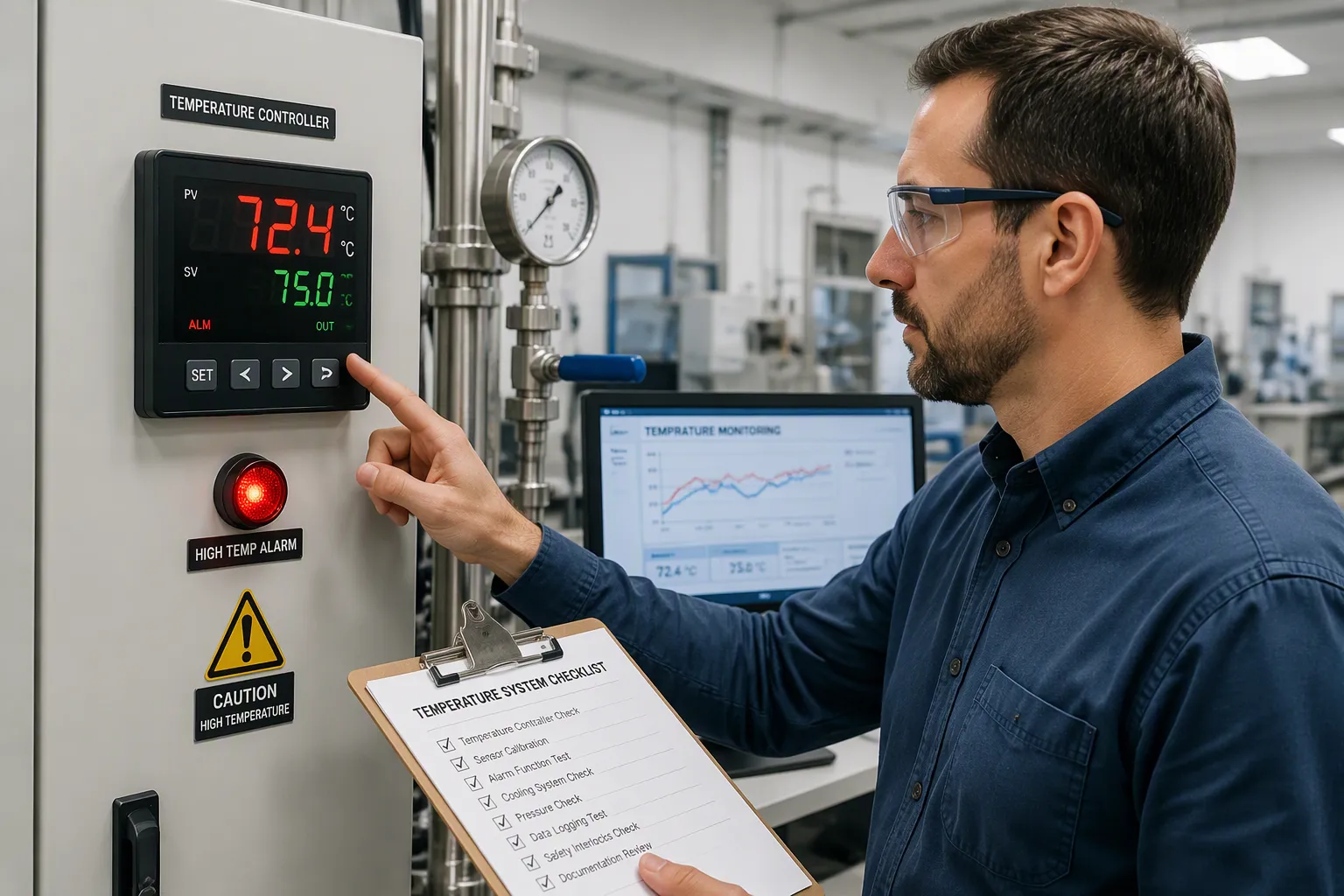
Accurate temperature control keeps a process at an exact target within a tight range. Overtemperature protection is a safety feature that stops temperatures from going past safe limits. A power board in an oven controller shows why both matter. The control loop keeps the heating element at the set point, and the protection circuit is ready if that loop fails.
Hardware engineers and electronics product teams see this pairing at the board level every day. One path measures temperature and drives the heater. A separate path watches for faults and cuts power when heat rises too far. The two functions share a thermal path, but they serve different goals. Design choices for sensors, wiring, and layout decide how well each one works.
Ringkasan Utama
Accurate temperature control keeps a process at an exact target. Overtemperature protection stops heat from going past safe limits.
Pilih yang benar sensor temperatur for what you need. RTDs give high accuracy over wide ranges. Thermistors work well in narrow bands.
Use PID control when you need tight temperature control. On-off control works for simple applications where temperature changes slowly.
Add separate perlindungan perangkat keras. A comparator and thermal fuse can shut off power if the control loop fails.
Mount sensors right on hot surfaces. Good thermal coupling makes sure the protection responds to real heat.
Accurate Temperature Control With Accurate Temperature Sensors
Sensor Choices and Error Budgets
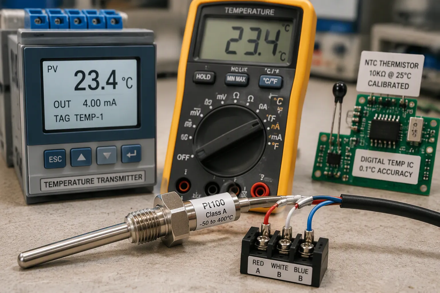
Accurate temperature sensors turn heat energy into electrical signals that control systems read and act on. Three main types lead board-level designs: thermistors, RTDs, and digital sensors. Each one offers different trade-offs for temperature sensor selection.
RTDs follow IEC 60751 tolerances. A Pt100 Class A sensor holds ±0.15°C at 0°C, though this range widens in a straight line as temperature rises—reaching ±0.35°C at 100°C. Class B offers ±0.30°C at 0°C. Termistor deliver ±0.05 to ±0.2°C accuracy within a narrow calibrated band, usually -50 to +150°C. They cost less but stop working outside that range. Digital temperature sensors are convenient, but retrieved sources do not state their accuracy limits.
Jenis Sensor | Akurasi pada 0 ° C | Catatan |
|---|---|---|
RTD (Pt100, Class A) | ± 0.15 ° C | Widens linearly with temperature (e.g., ±0.35°C at 100°C per IEC 60751) |
RTD (Pt100, Class B) | ± 0.30 ° C | Looser tolerance than Class A |
Thermistor (NTC, calibrated) | ±0.05 to ±0.2°C | Only within narrow calibrated band (~-50 to +150°C) |
Sensor suhu digital | Not specified in retrieved sources | No accuracy/error-budget data provided |
Wiring setup adds more error. In 2-wire circuits, lead resistance adds straight to the RTD reading and changes with ambient temperature. A 3-wire circuit cuts this error down but does not remove it—leftover error comes from resistance imbalance among the three leads. A 4-wire connection fully makes up for lead resistance because voltage leads carry almost zero current. Engineers should match sensor tolerance to measurement-hardware accuracy. Cabling, shielding, grounding, and closeness to other equipment all affect total accuracy. Calibration over the full operating range is required to prove accuracy.
Control Methods: On-Off vs. PID
On-off control fits applications where tight thermal control is not needed. The controller switches the heater fully on or fully off. Thermal lag between the heater and the temperature sensor causes overshoot. The sensor does not pick up heat right away, so the controller keeps the heater energized while temperature climbs. By the time the sensor reads the setpoint, extra energy has been added. The controller then overcorrects, which produces oscillation.
PID control gives smoother process temperature control. Engineers tune proportional, integral, and derivative gains to shape speed, stability, and damping. Start with small gains and raise them slowly. Higher Kp speeds response but risks overshoot. Higher Ki removes steady-state error but risks oscillation. Higher Kd reduces overshoot but increases noise sensitivity. Apply a low-pass filter to smooth the error signal. Add feedforward control to get ahead of system changes. These strategies together achieve high accuracy and repeatability.
For temperature sensors in industrial settings, the choice between on-off and PID depends on the process. On-off works for ovens with slow thermal dynamics. PID suits applications demanding tight tolerance. Both approaches benefit from accurate sensors and careful tuning.
Overtemperature Protection and Safety
Redundant Hardware Protection
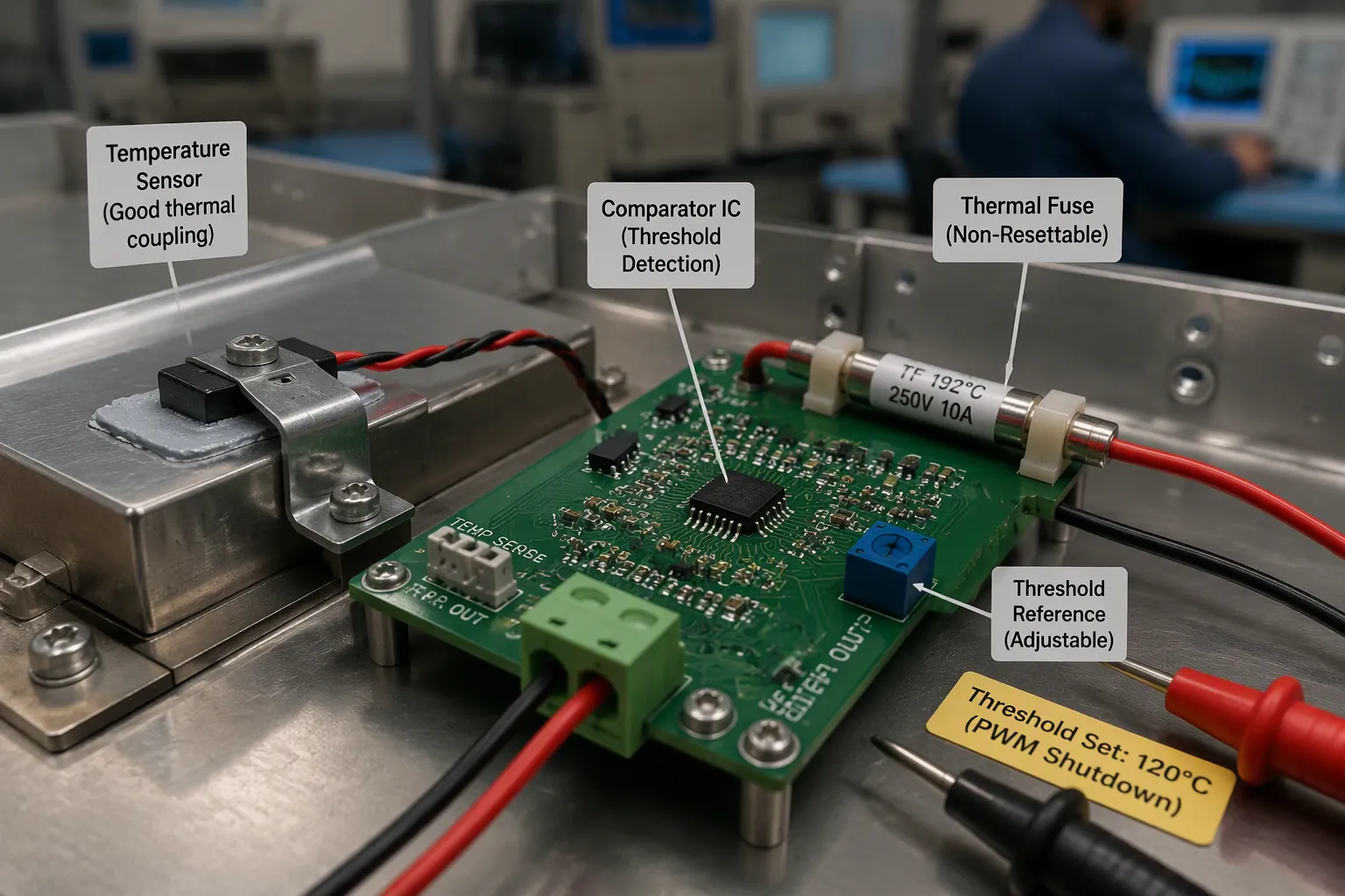
Firmware limits alone can’t keep things safe. A stuck control loop, a corrupted register, or a broken temperature sensor can let a heater run with no upper limit. Separate hardware layers catch that fault. A comparator watches a dedicated temperature sensor and pulls the heater enable line low when the reading passes a fixed threshold. The comparator circuit sits outside the control firmware, so a software fault can’t turn it off. Thermal cutoffs and thermal fuses add a last, one-time layer. These parts open the circuit for good once they reach their rated functioning temperature.
Thermal fuse selection follows two rules. The rated functioning temperature (Tf) runs from about 72°C to well over 240°C across common series. The continuous operating temperature must stay at least 25°C below the rated Tf, which stops nuisance tripping during normal cycles.
Parameter | Nilai Khas / Pedoman |
|---|---|
Rated Functioning Temperature (Tf) range | ~72°C to well over 240°C (varies by series/part number) |
Continuous operating temperature margin | At least 25°C below rated Tf (to avoid nuisance tripping) |
Sensor mounting decides whether protection responds to real heat. A temperature sensor bonded with a gap to the board reads the air, not the power stage. Teams should clamp or glue the sensor body right to the hot surface, use thermal compound, and route its traces away from heat sources. Good thermal coupling keeps sensor readings honest under fault conditions.
Standards and DFM Constraints
Safety standards shape the protection circuitry on manufactured boards. IEC 61010-1 covers measurement, control, and laboratory equipment. IEC 60950-1 is still valid in some countries, though IEC 62368-1 replaces it. IEC 60601-1 governs medical electrical equipment. Each standard requires safe behavior under normal operation and under a single abnormal fault, such as blocked cooling vents or a component short. Temperature tests run across the specified ambient range to limit burn and fire risk. Touchable-surface limits appear in table 19 of IEC 61010-1, table 4C of IEC 60950-1, table 38 of IEC 62368-1, and tables 23/24 of IEC 60601-1. IEC 62368-1 also sorts thermal energy categories TS1 through TS3 by user type.
DFM constraints push back on protection design. Thermal fuses need hand placement or selective soldering because wave solder can trip them. Comparators need their own reference and supply decoupling. Test access points let production check trip thresholds without stressing parts. Over-temperature protection is common practice in furnace and oven control systems and similar high-power designs, where a failed driver can dump full power into a heating element. These boards pair a comparator layer with a thermal cutoff so no single fault reaches a hazardous conditions state.
Temperature Monitoring for Safety and Efficiency
How the Two Systems Differ
Accurate temperature control is about quality. It keeps cycle times steady and means operators have to step in less. Overtemperature protection is about preventing damage. It stops fire, failure, and ruined hardware. Both systems read the same thermal path, but they answer different questions.
Atribut | Control loop (RTD-based) | Protection path (PTC-based) |
|---|---|---|
Ketepatan | High, within ±0.1°C to ±0.5°C | Threshold detection, limited precision |
Response time | Slower, built for stable measurement | Respon termal cepat |
Peran utama | Kontrol umpan balik | Fail-safe cutoff |
RTDs give better linearity and accuracy over wide temperature ranges. PTC sensors are great at fast thermal protection, not precise measurement.
Temperature monitoring brings the two together. Real-time monitoring feeds the lingkaran kontrol, and a separate path watches for faults. A head-end unit like a PLC or DAQ card makes a control voltage. A comparator in each cell checks that voltage against a local reference and drives current through the thermistor. The measured voltage gives resistance, and resistance gives temperature. Interfaces such as Modbus or 4-20 mA outputs carry the result to the controller.
Complementary Roles on the Board
Heater driver topology and power stage layout put both functions on one thermal path. The control temperature sensor sits near the element for feedback. The protection sensor sits at the hottest point for fast trips. Both temperature sensors share the same copper. Cascade control helps here. A slave loop on jacket temperature responds at least 5× faster than the master, so it trims heater output early and limits overshoot.
Reliable control stabilizes cycle times and protects equipment. Protection guards against control failure and keeps things safe. Continuous temperature monitoring supports both goals, and continuous temperature monitoring also links keamanan dan efisiensi. Careful accuracy in the sensors lifts energy efficiency. Overheating becomes a caught fault, not a lost board. Safety and efficiency both rest on trustworthy readings from accurate temperature sensors and steady temperature monitoring.
Accurate temperature control holds a process at a precise target within a tight tolerance. Overtemperature protection stops heat from crossing safe limits when something fails. The first function protects quality and performance. The second protects safety and equipment. Calibration across the full operating range makes sensor readings trustworthy. Independent hardware protection makes the cutoff trustworthy, even when firmware or the control loop fails. Together, these practices support safety and efficiency on every board a team ships.
FAQ (Pertanyaan Umum)
What is the difference between accurate temperature control and overtemperature protection?
Accurate temperature control keeps a process at an exact target within a tight range. Overtemperature protection stops heat from going past safe limits when a fault happens. The control loop depends on temperature sensors for feedback. The protection path uses separate sensors to trip fast. Both functions share the same thermal path on the board, but they use different sensors.
Which temperature sensor type suits tight tolerance applications?
RTDs give strong linearity over wide ranges. A Pt100 Class A sensor holds ±0.15°C at 0°C per IEC 60751. Thermistors deliver ±0.05 to ±0.2°C within a narrow band. Digital sensors have no stated accuracy limits in the sources. Engineers should match sensor suhu to the measurement hardware. Calibration proves accuracy for all these sensors.
Why do redundant hardware protection layers matter beyond firmware limits?
Firmware limits fail when a control loop sticks or a register corrupts. A comparator watches a dedicated sensor and pulls the heater enable line low. Thermal cutoffs and thermal fuses add a one-time layer. These parts open the circuit at their rated functioning temperature. Independent hardware catches faults that software cannot. Separate sensors make this layer trustworthy.
How does sensor mounting affect protection response?
A sensor bonded with a gap reads air, not the power stage. Teams should clamp the sensor body to the hot surface and use thermal compound. Temperature monitoring feeds the control loop, and a separate path watches for faults. Reliable sensors support safety and efficiency. Careful mounting helps temperature monitoring catch real heat. Well-coupled sensors protect the board.