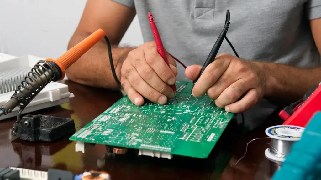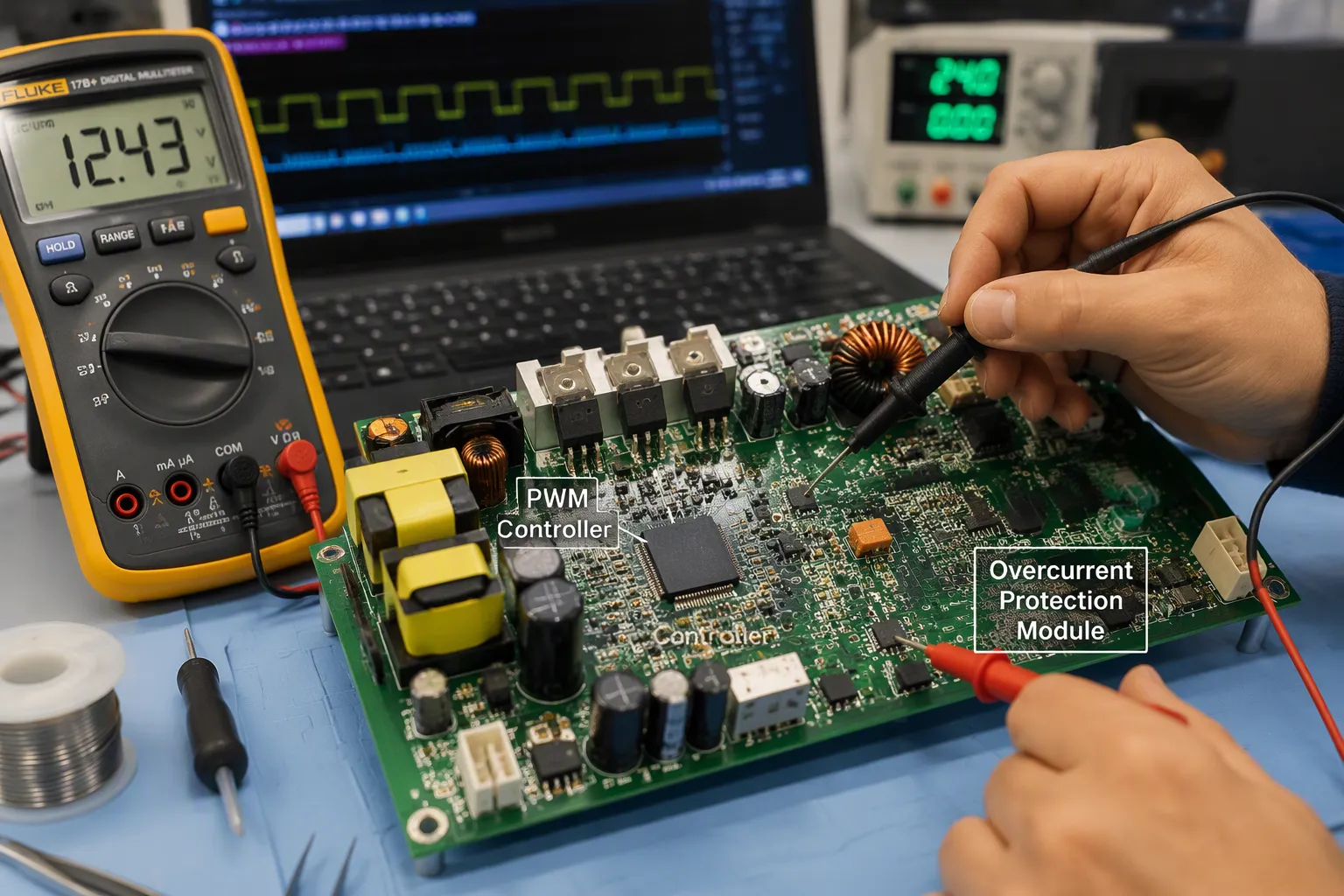
PWM control manages power by turning devices on and off fast with a changing duty cycle. Overcurrent protection checks the current and quickly adjusts or shuts off the PWM signal to stop damage.
You cannot treat these functions as separate blocks in a real power stage. The PWM switch makes the current, and the protection circuit must act on that same switch. A slow OCP response leaves the hardware open to overcurrent damage.
Integration matters because detection, decision, and shutdown share one control loop. You will see how duty cycle sets output, how sensing catches faults, and how a controller runs both roles safely.
Ringkasan Utama
PWM control uses duty cycle to set the output voltage in an efficient way.
Overcurrent protection quickly shuts off the switch to stop damage.
Quick current sensing and response are very important for safety.
Soft start and dead time help prevent false trips and shoot-through.
A clear sensing network makes sure protection and control work accurately.
PWM Control Basics
Duty Cycle and Average Output
Pulse width modulation takes a steady DC input and breaks it into on and off periods. The width of each on pulse decides how much energy gets to the load. This is the core of pwm control.
The duty cycle is the part of each period the switch stays on. You can state the average value of a pwm waveform simply: average output equals duty cycle times peak voltage. A duty cycle of 0.5 with a 12 V peak gives 6 V average. Raise the duty cycle and the output voltage goes up. Lower it and the output voltage goes down. That direct link is why pwm output control gives such exact regulation.
Switching, Filtering, and Efficiency
A raw pwm signal is a stream of pulses, not a steady level. An inductor and capacitor filter stage smooths those pulses into a clean output voltage. The filter takes out most of the switching ripple. What is left is a small, expected variation.
This switching method is much more efficient than linear regulation. In a 12 V to 3.3 V synchronous buck design, a switch-mode supply usually goes above 90% efficiency. A linear regulator in the same role gives under 27.5%. The gap comes from how each part deals with extra energy. A linear pass element burns the difference as heat. A switch-mode power supply instead moves energy in packets, so losses stay low.
Most pwm-based control circuits follow this pattern. You will find the same building blocks in any pwm power supply circuit: a switch, a filter, and a feedback loop. A pwm power supply circuit diagram shows these parts clearly. The controller watches the output voltage and adjusts the duty cycle to hold it steady. This closed loop is what makes a pwm power supply reliable across load changes. The switch current stays controlled, and the output stays clean.
Overcurrent Protection Fundamentals
Current Sensing Methods
You need a way to measure current before you can protect anything. Resistive shunt sensing is the most common choice. It measures the voltage drop across a known impedance, so it follows Ohm’s law directly. Shunt resistors work well for switch-mode power supplies because they are low-cost and easy to understand. They do waste power as heat, and they offer no isolation.
Hall-effect sensors avoid that insertion loss. They also cost more and need external power. Current transformers work only for AC, so they cannot serve a DC rail. The table below compares the three main options.
metode | Kekuatan | Batas |
|---|---|---|
Resistive shunt | Low cost, simple, widely used | Insertion loss, no isolation |
Efek Hall | Tidak ada kerugian penyisipan | Higher cost, needs external power |
Trafo arus | Isolation, no offset at zero load | AC only, narrow frequency range |
A shunt resistor provides overcurrent protection by watching the circuit flow continuously. It triggers a shutdown when an overcurrent event exceeds safe limits.
Thresholds and Response Times
Peak current limiting senses the top switch. You set a peak current limit threshold, and the controller trips when the switch current crosses it. Peak current limiting responds within one switching cycle. Valley current limiting instead watches the bottom switch. It catches overcurrent faults that appear during the off time.
Response time decides how much fault current reaches the hardware. A slow trip lets the flow climb far past the threshold. Fast cycle-by-cycle current limiting stops the pulse immediately. The sensing logic then disables the supply by switching the pwm signal off. This is how ocp works inside a peak cmc buck converter. A current-mode control (cmc) buck converter relies on this loop every switching cycle. Peak current limiting also sets the trip point for the top device. You rely on peak current limiting for fast faults. Peak current limiting and valley limiting work as a pair. The same scheme protects a standard buck converter and any current-mode control design. Cycle-by-cycle current limiting also guards against a shorted output. That protection keeps the ocp response fast and predictable.
How PWM and Overcurrent Protection Interact
Overcurrent Detection and PWM Response
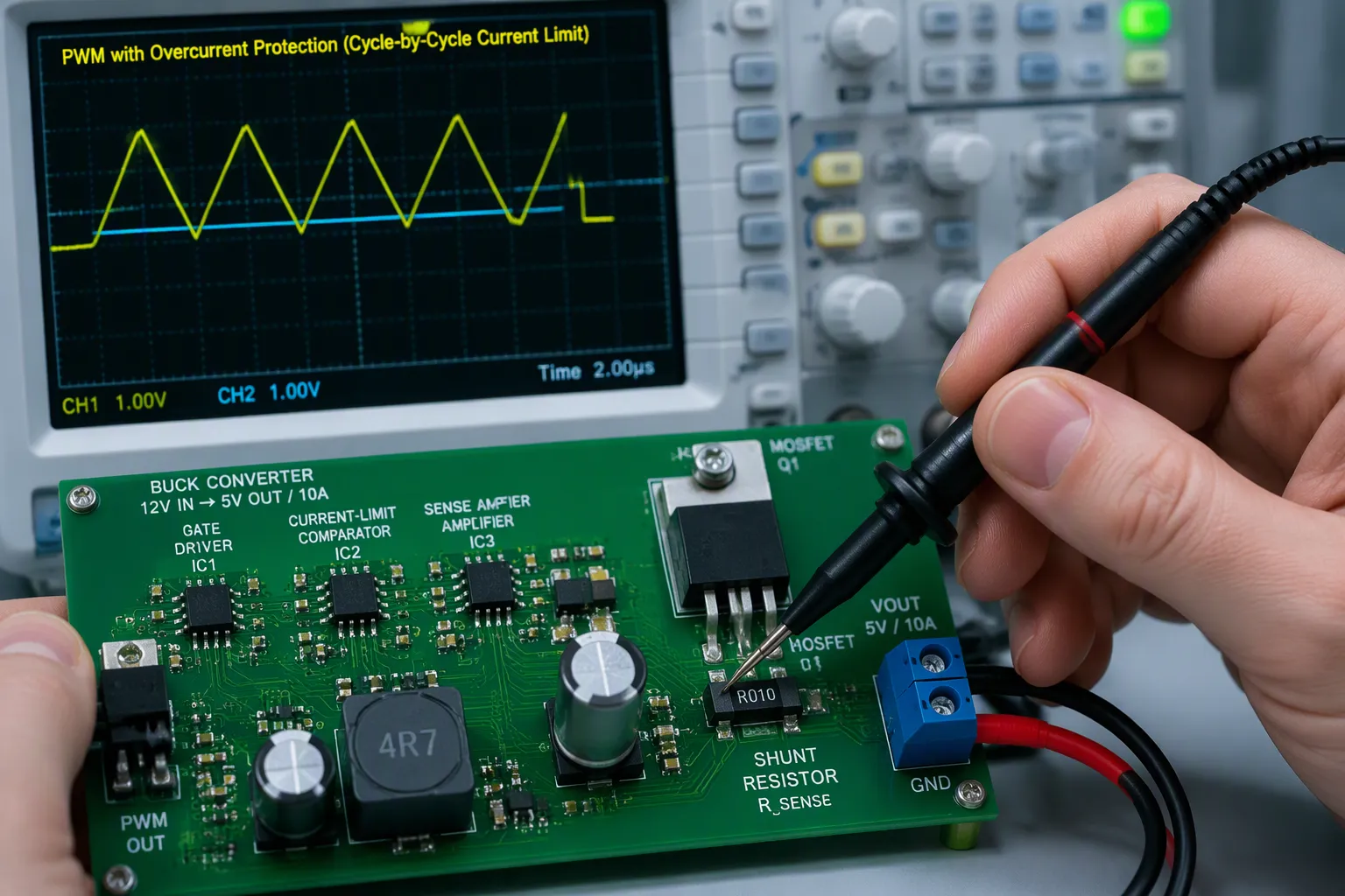
A controller checks the current every switching cycle. It compares the sensed level to the peak current limit threshold. When the level crosses that line, the controller turns the switch off. This is the heart of pwm control under fault. Peak current limiting acts on the top switch.
The detection path follows a fixed sequence:
A shunt resistor or sense amplifier makes a signal that matches the current.
The controller compares that signal to the threshold.
The driver turns off the MOSFET and cuts the on-state short.
The switch turns back on when the level falls below a lower bound.
The result is a triangular pwm waveform whose average follows the load. In a peak cmc buck converter, this same comparison sets the trip point for the top device.
The edge-control scheme matters here. The rising edge of the pwm signal passes straight through a diode. The trailing edge is managed for conduction. This split lets the controller cut the pulse short without fighting the gate driver.
A bad sense network can fool the whole loop. In a TPS40090-based design, the switching signal became uneven as input voltage rose, and the soft-start terminal kept charging. Over-voltage and under-voltage protection were ruled out. Overcurrent was the remaining suspect. The CSCN pin never reached its intended 1.5 V reference because it drew a lot of sink current. That fluctuation falsely triggered protection. Drive the sense network from a low-impedance source to keep the threshold accurate.
Shutdown, Duty-Cycle Limiting, and Soft Start
The controller has several response tools. Each one trades speed against stress.
Mekanisme | Response |
|---|---|
Peak current limiting | Turns off the high-side switch at the threshold |
Valley current limiting | Skips the next cycle when valley current is too high |
Modus cegukan | Shuts off after repeated trips, then retries |
Latch-off mode | Shuts down until you toggle ENABLE or VIN |
Mulai lembut | Limits first on-time so the output capacitor charges slowly |
Shutdown and latch-off handle long faults. Hiccup mode lowers power loss and heat. Latch-off mode stops battery drain. Both sit above the fast layer. Peak current limiting handles the first pulse. Cycle-by-cycle current limiting keeps each pulse short. A second cycle-by-cycle current limiting stage counts trips. After a set number of cycles, the ocp logic shuts the regulator down. The ocp path then retries or latches. Either way, the ocp response stays predictable.
Soft start protects the startup window. A high on-time at switch-on keeps the inductor current climbing. The inductor can saturate, and the switch current can spike. A low first on-time lets the output capacitor charge without that inrush. Peak current limiting caps the pulse during this ramp. This is the simplest overcurrent protection mechanism you can add.
The same logic runs inside any pwm power supply. Switch-mode power supplies rely on closed-loop feedback control to hold the output steady. That feedback control loop also carries the fault signal. Pulse width modulation sets the normal operating point. The ocp path overrides it when current runs away. You can see both roles in one pwm output control scheme. Output pwm voltage control and current limiting share the same comparator in many designs. Current-mode control makes that sharing clear.
Consider a 12 V to 3.3 V buck with a 5 A load. At startup, the output capacitor looks like a short. Without soft start, peak current limiting trips on the first pulse. Cycle-by-cycle current limiting keeps the pulse short, and the output voltage climbs slowly. With soft start, the duty cycle ramps slowly. The current stays under the limit, and the loop reaches regulation cleanly.
PWM Protection Design Considerations
Sensing Accuracy and Noise Immunity
Kamu harus balance sensing accuracy against noise immunity, and that is a hard trade-off. Modern wide-bandgap converters make strong EMI at high switching frequencies. That noise can cause false detection and wrong measurements. A protection sensor must catch fault currents fast, but it must also survive very high fault currents and reject switching noise. No single scheme meets accuracy, speed, size, thermal stability, and EMI immunity all at once.
Tujuan Desain | Trade-off / Cost |
|---|---|
Higher sensing accuracy | May make the sensor bigger |
Peningkatan kekebalan terhadap kebisingan | May need a more complex circuit |
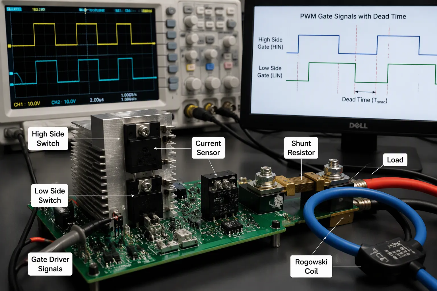
Resistor shunt | Wide bandwidth but poor isolation and accuracy that changes with temperature |
Kumparan Rogowski | Good high-frequency sensing but cannot detect DC |
In-line (phase) sensing gives the most accurate picture of the load current, because the sensor stays in series with the load no matter the switching state. But it puts the sensor in the worst noise spot: the common-mode voltage swings between the DC bus and ground at the PWM switching frequency, so the sensor sees extreme dV/dt transients. This requires strong galvanic isolation plus excellent Common-Mode Transient Immunity (CMTI) to keep high-frequency PWM noise from corrupting the analog output—so getting the most accuracy here directly adds to the noise-immunity burden on the design.
Good pwm in power supply design starts with a clean sense network. Drive the sense node from a low-impedance source. Keep the peak current limit threshold steady across temperature. A noisy sense line can trip the ocp path on a healthy load.
Dead Time and Fault Handling
Dalam prakteknya, deadtime is needed to avoid shoot-through in a real half-bridge.
A half-bridge with two outputs needs a gap between the top and bottom gate signals. Without that gap, both switches conduct at the same time. The DC bus then drives a huge current through the pair. The controller must set dead time or prevent overlap to block this shoot-through path.
A worked example shows how the parts work together. Suppose a peak cmc buck converter runs a 12 V rail into a shorted load. The peak current limit threshold trips on the first pulse. Peak current limiting cuts the high-side switch. Cycle-by-cycle current limiting holds each pulse short. After repeated trips, the ocp logic latches off. Peak current limiting and cycle-by-cycle current limiting work together here. The same pattern protects any pwm power supply. You can trace it in a pwm power supply circuit diagram or a pwm power supply circuit. The pwm waveform stays clean, and the output voltage recovers once you clear the fault. Switch-mode power supplies depend on this layered response.
PWM control gives you power regulation that works well. Overcurrent protection keeps things safe. When they work together, you get fast, reliable protection without slowing down normal operation. One control loop watches input voltage, load, and current, then drives the switch. That same loop has safeguards built in that act on the signal. Fault-responsive switching lets the PWM gating cut power the moment an overcurrent event shows up. Built-in diagnostics report faults as they happen.
You have to balance sensing accuracy against noise immunity, and dead time against shoot-through risk. The OCP path only works when the sense network stays clean. Modern designs push switching faster and rails tighter. That makes this combined approach a must, not a choice. Your output voltage stays steady, and your hardware survives the fault.
FAQ (Pertanyaan Umum)
Why does a slow protection trip damage hardware?
A slow trip lets the fault current climb far past the threshold before the switch turns off. The extra current stresses the MOSFET and the inductor. Fast cycle-by-cycle limiting stops each pulse at the limit, so the hardware never sees that runaway current.
Can you use one sense resistor for both regulation and protection?
Yes. Many controllers share one comparator between the feedback loop and the current limit. The same shunt signal sets the normal operating point and the trip point. You save parts and board space, but the sense network must stay clean for both roles.
What happens after the controller trips on a fault?
The first response cuts the pulse. Repeated trips then trigger hiccup mode or latch-off. Hiccup mode retries after a pause and lowers heat. Latch-off mode stays off until you toggle the enable pin or cycle the input voltage.
Why does shoot-through cause an overcurrent event?
Both switches conduct at the same time, so the DC bus drives a huge current straight through the pair. The ocp path may trip, but the stress arrives fast. You prevent it by setting dead time or blocking overlap between the two gate signals.
Does soft start replace overcurrent protection?
No. Soft start only limits the first on-time, so the output capacitor charges slowly and the inductor current stays low. A real short still needs the current limit. Soft start and protection work as layers, not substitutes.