A transceiver comes back from the field with a hole where its line driver used to be. The customer says lightning struck nearby, not a direct hit. You test the IC by itself and it passes every bench check. The real cause is somewhere else: the surge protector clamped too slowly, its leads were too long, and the path back to earth was never designed. The part did its job. The system did not.
Surge suppression and grounding are your job as the designer, not the IC vendor’s. Skip them and you get RMA cycles, repeat field failures, and safety risk. So how does transient voltage stress a junction under IEC 61000-4-5? Why must protection stages work together? Where does a surge protection device belong, and how do grounding and layout decide whether lightning/surge protection works at all?
주요 요점
Figure out your surge environment and test levels first. This will guide every choice you make later.
Make the protection stages work together. Add impedance between them so they share the surge energy.
Keep the surge protector’s wires short and straight. Long wires make the extra voltage higher.
Plan the path to earth before you lay out the board. A short ground path with low inductance makes the protection work.
Follow creepage, clearance, and DFM 규칙. These rules stop transients from jumping across gaps.
Surge Threats at the Board Level
IEC 61000-4-5 Test Levels
IEC 61000-4-5 sets the surge waveforms you design against. The combination wave generator is the most common source. It sends out a 1.2/50 µs open-circuit voltage and an 8/20 µs short-circuit current, so engineers call it the “1.2/50-8/20 µs” surge. Its effective output impedance is 2 Ω, which is the ratio of peak open-circuit voltage to peak short-circuit current. Outdoor telecommunication equipment faces a higher-energy generator instead, with a 10/700 µs voltage wave and a 5/320 µs current wave.
Waveform Set | 전압파형 | 현재 파형 | 일반적인 응용 프로그램 |
|---|---|---|---|
조합 파 | 1.2µs / 50µs | 8µs / 20µs | 대부분의 응용 프로그램 |
Higher-energy generator | 10µs / 700µs | 5µs / 320µs | Outdoor telecommunication networks |
Front time and duration are virtual parameters, not simple rise times. For the open-circuit voltage, front time equals 1.67 times the 30%–90% rise time. Match your product standard to a test level before you pick parts. The generator impedance tells you how much current a given voltage pushes into your board.
How Surges Stress Semiconductor Junctions
A lightning or switching surge reaches your board in two ways. Common-mode transient voltage pushes current through the interface cable and back through earth. Differential-mode transient voltage shows up across the signal pair itself. Both couple into traces as electrical surges and spikes, and both hit the weakest junction first.
Semiconductor junctions fail first because they crowd current into a tiny volume. A transient voltage that goes past the reverse breakdown region dumps energy into a small silicon area. Local heating follows, and the junction shorts. This is why a surge protector at the connector matters more than a robust IC. The clamp must divert energy before it reaches the die.
Define your surge environment and test level first. Every later choice, from the surge protection stage to the layout, depends on that number.
Staged Surge Suppression Architecture
One device cannot soak up a lightning surge and still clamp tightly at the IC. You need a staged protection system. Each stage handles the energy it is good at, and the stages share the stress.
Coordinating MOVs, GDTs, and TVS Diodes
The three-stage model puts a gas discharge tube (GDT) at the service entrance, a metal-oxide varistor (MOV) in the middle, and a transient-voltage-suppression diode (TVS) near the protected circuit. A service entrance surge protection stage diverts the bulk current. The middle stage absorbs what passes. The final stage clamps the residual voltage at the IC pin.
매개 변수 | GDT | MOV | TVS 다이오드 |
|---|---|---|---|
응답 속도 | 100ns – 1µs | 1~25ns | 서브나노초 |
Surge current handling | 5~100kA | 500 A – 40 kA | 10 – 500A |
에너지 흡수 | High (kJ via arc) | 10 J – 2 kJ | 0.1~50조 |
Clamping behavior | 바 | Moderate clamping ratio | Tight clamping ratio |
Coordination depends on decoupling impedance between stages. Add inductance or resistance so surge energy spreads across the chain. Without it, the fastest device fires first and absorbs the whole event. A TVS clamps the overshoot in picoseconds. Rising voltage across the series impedance then triggers the MOV in nanoseconds. Extreme current ignites the GDT arc within hundreds of nanoseconds and dumps tens of kiloamperes to ground.
Clamping Versus Crowbar Behavior
A metal oxide varistor and a transient voltage suppressor clamp. They hold the voltage at a defined level and dissipate the energy themselves. A GDT and a SIDACtor crowbar. They break over, then latch into a low-voltage conductive state.
A crowbar’s low holding voltage lets it carry a higher fault current with little power dissipation, so it can sustain higher currents for longer periods than a clamp.
That strength comes with a condition. The crowbar stays latched unless the circuit clears the follow current. You must add a fuse, a PTC, or source impedance that limits current below the holding level. Verify that clearing across temperature extremes. A clamping device needs no clearing, but it stresses itself on every event. MOVs degrade after repeated hits. TVS diodes outlast them but handle far less energy.
Backup fuses protect against a shorted surge protector. Size the fuse above the normal operating current and below the device’s fault current capability. Check the failure mode of each part. A shorted MOV or TVS usually means the surge exceeded its rating. Elevated leakage current points to degradation from repeated surges. Repeated failures mean you chose too small a device. Communication errors on data lines often trace to a high-capacitance part. Poor placement far from the connector also weakens any surge suppression and filtering scheme.
Selecting a Surge Protection Device
Sizing and Clamping Voltage
Begin with the standoff voltage. The reverse standoff voltage has to be higher than the highest normal line voltage. That includes supply tolerance, ripple, overshoot, and temperature changes. A 5V rail may reach 5.25V or 5.5V during normal operation, so a 5V standoff may leak or turn on in normal use. Do not mix up breakdown voltage with standoff voltage. Low leakage is promised at the standoff rating, not at the breakdown point.
매개 변수 | 의미 | 선택 규칙 |
|---|---|---|
Reverse standoff voltage | Highest continuous voltage with specified low leakage | Must be greater than the maximum valid line voltage |
클램핑 전압 | Voltage across the device during a defined pulse | Must stay below the protected circuit’s safe transient limit |
피크 펄스 전류 | Maximum pulse current for a given waveform | Must exceed the expected transient current |
Peak pulse power | Maximum short-duration pulse power | Must exceed the derated calculated pulse power |
Next, estimate the surge current and check the clamp. For a 24V industrial input, a 33V standoff works. With a 1000V source, a 54V clamp, and 42Ω source resistance, the 8/20 µs pulse current is about 22.5A. If the protected circuit can take 60V, that 54V clamp leaves only 6V of margin before PCB overshoot. Never ignore clamping voltage. A diode may live through the pulse but still let enough transient voltage through to damage the protected IC.
Do not pick a standoff voltage from the nominal rail alone. Make sure the datasheet waveform matches the expected threat, and apply temperature derating to peak pulse power.
Placement and Lead Length
넣어 서지 보호 장치 at the connector, before the trace goes anywhere else. Long connecting leads add impedance and inductive voltage drop. When high-frequency transient current flows, that impedance raises the leftover clamping voltage that reaches downstream equipment. The protection level drops, and sensitive loads see voltages above their impulse withstand rating.
Keep leads short, straight, and direct. The suggested maximum lead length between the arrester and the mains network or earth is 0.5 meters, often called the 50-centimetre rule. Cables between the arrester and equipment should not go past 10 meters. Beyond that, add a second coordinated surge protector closer to the equipment.
Lead length for connecting the surge arrester to equipment terminals and to ground should be minimized and installed as straight as possible, minimizing bends.
DFM constraints shape the choice here. Fine-pitch transient voltage suppressor packages limit pad size and standoff clearance. Place the part on the surge entry side of any split, and keep the return path on the same layer. A listed and properly rated surge protective device still fails if the assembly house cannot hold the pad geometry.
Grounding Design for Surge Protection
Protective Earth Versus Signal Ground
Protective earth and signal ground do different jobs. Protective earth carries fault current and keeps the chassis at earth potential. This way, a person who touches the enclosure stays safe. Signal ground is the reference for your circuit. It can sit at any voltage compared to the chassis. Treat them as separate nets until you decide where they meet.
아래 | 지도 |
|---|---|
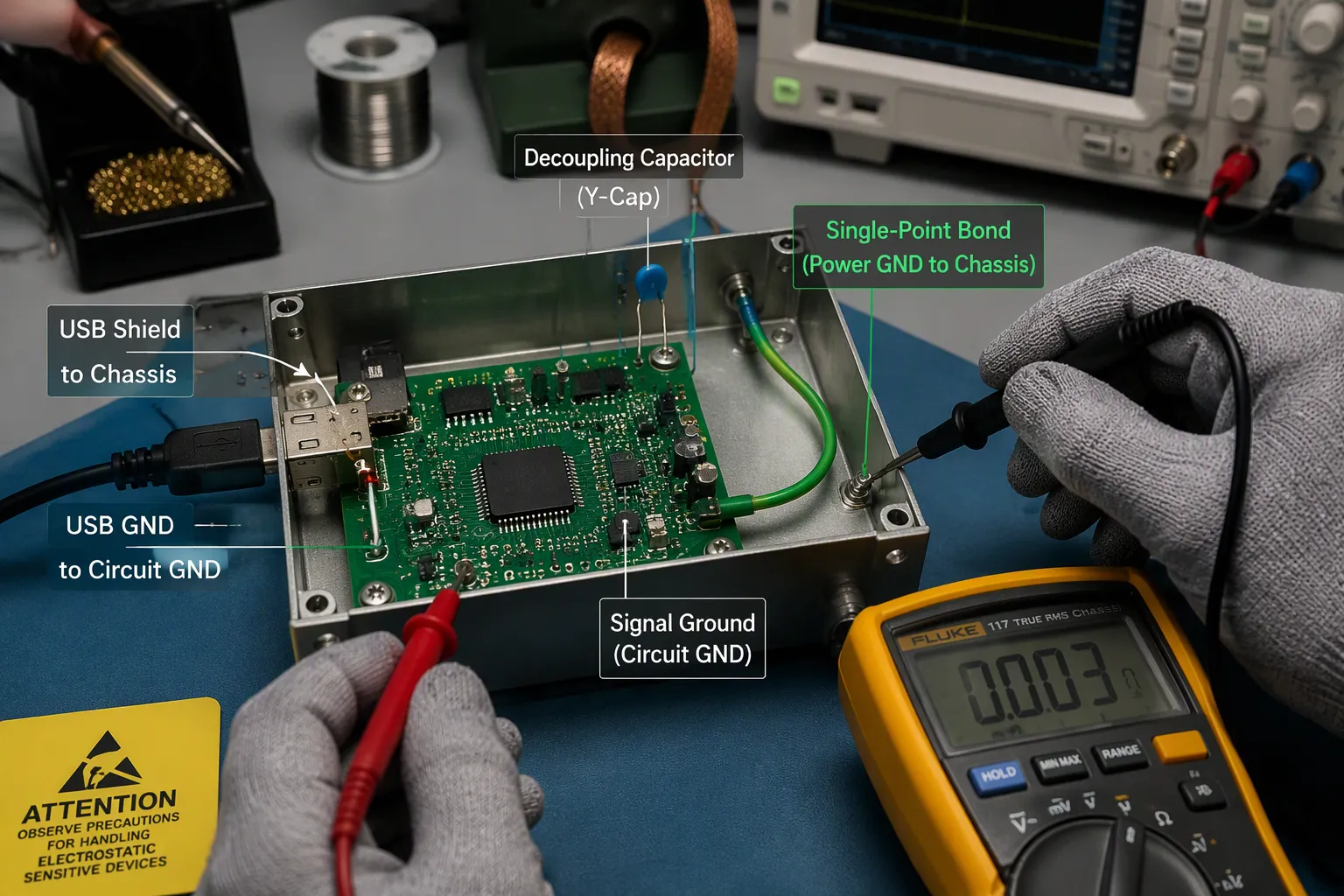
Signal ground vs chassis ground | Circuit ground does not have to connect to chassis ground. On a USB-powered device, the GND wire goes to circuit ground and the shield goes to chassis. |
Single-point bonding | Tie the circuit power ground to the chassis at one point only. |
High-frequency bonding | Add a small capacitor of a few hundred pF from circuit GND to the shield to shunt high-frequency noise. |
Shield handling | Keep the shield and signal return as separate points. A shield blocks fields and should not carry current unless you design it to. |
Noise and loops | Separating the circuit reference from the shield splits noise paths from signal return paths. This avoids ground loops, oscillation, and supply hum. |
Bond the chassis to signal ground at one point, then add the small capacitor for high-frequency return. This keeps the safety bond solid and gives noise a short path at high frequency.
Single-Point, Multipoint, and Hybrid Grounding
Single-point grounding ties every return to one common node. It limits ground loops and holds all parts at a common potential during a lightning storm. It stops working above roughly 10 MHz, where long conductors act as antennas. Multipoint grounding gives ground currents many paths and equalizes potentials. It also invites loops and stray current through building steel. Hybrid grounding mixes both: a single-point backbone with multipoint subsystems.
For circuits operating between 1 MHz and 30 MHz, a hybrid approach is used. If the ground wire length is less than 1/20 of the operating signal’s wavelength, use single-point grounding. Otherwise, use multi-point grounding.
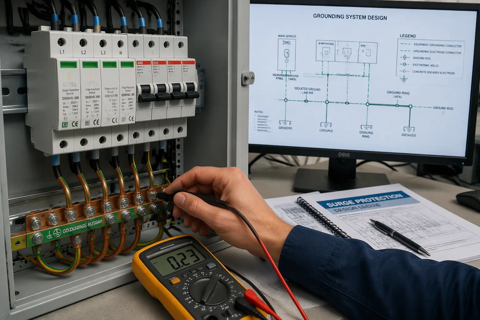
Plan ground plane splits and stitching with the return current in mind. A split under a signal forces its return current to detour, and that loop radiates. Stitch across the split with capacitors or a narrow bridge where a signal must cross. Design the earthing arrangement for the surge protective device and the protected equipment together. The surge protector needs a short, low-inductance pathway to earth. The equipment needs its own reference. Run the grounding conductor from the surge protective devices to a common earth point, and keep that conductor separate from signal returns. Bond the phase, neutral, and equipment grounding conductors at the service entrance as your local code requires. Then ground the suppressors at that same point. A long, shared ground wire raises the transient voltage across every stage and defeats the coordination you built. Effective lightning protection depends on this shared earth reference, not on the suppressor alone. Route the surge suppression return first, then place the signal grounds around it.
PCB Layout and Isolation Techniques
Creepage, Clearance, and Slotting
Creepage is the path along the surface between two conductors. Clearance is the straight-line gap through the air. A transient voltage will jump across either one if the distance is too short. Cut a slot between high-voltage pads and you make the surface path longer. A 1 mm wide slot between pads can almost double the surface path length. That sharply lowers the chance of tracking or arcing. A 2 mm wide slot adds several millimeters to the creepage path without making the board bigger.
Use slots and physical barriers when board size makes large creepage distances hard to keep. A compact 800V converter can meet its spacing with a 1 mm slot plus a good insulating material. An industrial motor controller at 1200V (pollution degree 2, IPC-2221, Group II material) pairs a slot with conformal coating to pass on a small board. Avoid sharp trace turns and edges, because they crowd the electric field. Keep very high voltage traces off internal layers. Any metal pattern with a sharp edge can raise the field across an insulator and cause flashover.
Common Mode Chokes, Y Capacitors, and Isolation Barriers
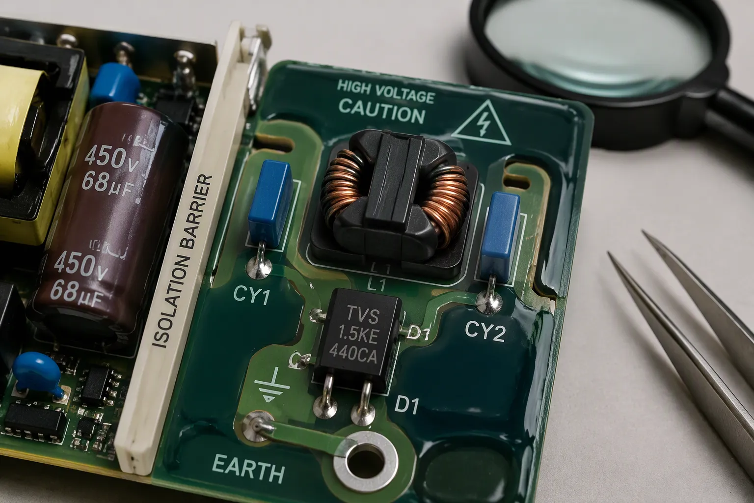
A common mode choke blocks noise that is common to two or more power lines. Its opposing windings cancel for differential current and show high impedance to common-mode noise. Place it near the mains input and coordinate it with X and Y capacitors and the surge protection stage. Y capacitors shunt common-mode noise to earth. X capacitors filter differential-mode noise across line and neutral. Together with the transient-voltage-suppression diode and the other surge protective devices, these parts form the surge suppression and high frequency filters that keep leftover transient voltage off the IC.
A ferrite choke saturates. A high-energy common-mode surge can saturate the core and pass straight through. Design separate surge protection in addition to the choke, and never treat the choke as the surge suppressor. Size Y capacitors by their class rating under IEC 60384-14, and confirm the part withstands your target peak voltage.
DFM shapes all of this. Copper sits about 0.3–0.4 mm off the outline for fab rules, yet creepage then runs around the edge to the chassis. An isolation slot cannot be plated, and routing needs roughly 1.0–1.5 mm, so the electrical path must clear the slot ends. Flux and solder balls in the isolation zone act as installed pollution. Treat that belt as a keepout for parts, vias, silk, and testpoints. Do not shrink creepage in CAD on the assumption of coating unless you specify and inspect it.
Constraint Area | Manufacturing Trade-off |
|---|---|
Board edge creepage | Copper pullback leaves a path around the edge to chassis |
Isolation slot | Cannot be plated; routing width forces the path around slot ends |
Vias along barrier | Narrow mask dams stitch pad-to-pad on the surface |
Assembly residue | Flux and solder balls act as pollution in the isolation zone |
등각 코팅 | Lowers pollution degree only if specified and inspected |
A short burst of high voltage comes in at the connector. It finds the weakest spot in a chip and breaks it. Staged protection slows that energy down. Grounding and layout then decide if the clamp holds. Surge protection is a whole system, not just one part.
Here are the key points again. First, define your surge environment and test levels. Make the MOV, GDT, and TVS stages work together by adding impedance between them. Keep the surge protector’s leads short and straight. Plan the path to earth before you do layout. Follow the rules for creepage, clearance, and DFM limits. Place each surge suppressor so it shunts current to chassis ground.
현재 상태를 확인하세요 surge suppression, grounding, and layout plan against these ideas before the next build.
FAQ
Why does a transceiver fail when the surge protector looks fine?
The protector may have clamped too slowly or sat too far from the connector. Long leads add inductive drop, so the leftover voltage at the IC rises above its limit. Check lead length and the return path to earth before you blame the part.
Can one TVS diode protect a board by itself?
No. A TVS clamps fast but handles little energy. A lightning surge exceeds its rating. You need a GDT or MOV stage ahead of it, with impedance between the stages so the energy spreads across the chain.
How short do surge protector leads need to be?
Keep the connection to the mains network or earth under 0.5 meters, straight and with few bends. Keep cables between the arrester and the equipment under 10 meters. Beyond that, add a second coordinated protector closer to the load.
Where should I bond chassis ground to signal ground?
Bond them at one point, then add a small capacitor of a few hundred pF for high-frequency return. This keeps the safety bond solid and gives noise a short path without creating a ground loop.