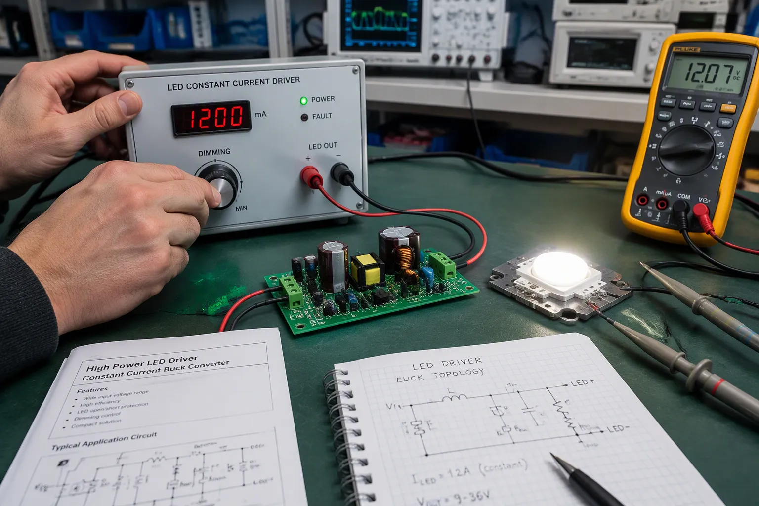
A dimmable led driver pairs a regulated output stage with a control interface. The led constant current driver holds the output steady while a dimming signal sets the target level. The regulation loop compares a sensed current against a reference. A dimming command shifts that reference, so controlled led brightness adjustments happen at the source. The LED string sees a clean, proportional drive level. Light output falls or rises smoothly, and the emission spectrum stays stable. Color shift and visible flicker do not appear. This dimmable led driver overview targets hardware engineers and electronics product teams. It stresses board-level design, method comparison, and manufacturing trade-offs.
الوجبات السريعة الرئيسية
Pick the dimming method that works with your current control system. This gives you smooth, flicker-free operation.
Use a precise current-sense resistor and careful layout to keep the LED current steady.
Keep the PWM frequency above 3 kHz. This helps prevent flicker you can see and health problems.
خطط ل thermal design and EMI layout early to prevent failures and ensure reliability.
Use a checklist for control, load, and compliance to avoid problems in the field.
How a Dimmable LED Driver Works
A dimmable led driver does two jobs at the same time. It keeps the LED current at a set value, and it changes that value when told to. The sections below cover the output stage, the sensing network, and the control path.
Constant Current Regulation and Current Sensing
Topology comes first. A linear driver uses a pass element as a variable resistor. A switching driver chops the input and filters the result through an inductor and capacitor. The table below compares the two at board level.
التنازل عن ميزة ممن أجل الحصول على أخرى | سائق خطي | Switching driver |
|---|---|---|
كفاءة الطاقة | Poor; the pass element burns (Vin − Vout) × Iload | High; typically around 90% |
تبديد الطاقة | Significant in the pass element | Low; the filter stores energy |
Cost and parts count | أقل | أكثر |
تعقيد التصميم | Simple pass element | Switch, filter, and tight fit in small form factors |
A buck works for strings below the supply rail, a boost works for longer strings, and a buck-boost handles rails that cross the string voltage. Linear stages fit low-current, cost-sensitive boards with plenty of headroom.
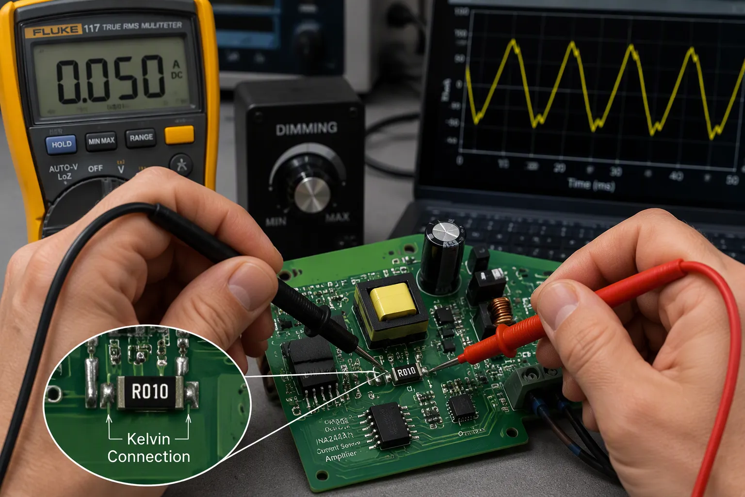
Accuracy depends on the sense resistor and how it is laid out. A tight tolerance part with low temperature drift keeps the constant current stable. Route the sense lines straight to the resistor terminals for a true Kelvin connection. Do not run sense traces parallel to high-current paths. Place the sense amplifier close to the resistor, keep the two traces symmetrical, and minimize loop area. Keep them away from switching nodes, and add guard traces when spacing alone fails. A clean ground return under the resistor stops load current from corrupting the measurement. This discipline separates constant current vs. constant voltage regulation in practice, because a voltage loop tolerates layout sloppiness that a current loop does not.
Dimming Control Mechanisms
Four dimming control mechanisms dominate تصميم المجلس. Analog dimming shifts the current reference, so the LED runs at a lower direct current. PWM dimming chops the LED current at a fixed frequency and varies the duty cycle. A shunt transistor across the string bypasses part of the constant current. External dimming signals, such as a 0-10V level or a digital bus command, feed any of these paths through an interface stage.
Analog and PWM behave differently in light output. Analog dimming makes no flicker, but it warms the color at low levels because LED color tracks current strength. PWM holds color steady at full drive, yet it runs at 100% modulation depth. Keep the PWM frequency above 3 kHz so long exposure causes no health symptoms. Below that, eye strain and camera artifacts appear.
Zero modulation means no flicker, whereas PWM driving yields 100% modulation depth; with 100% modulation the flicker frequency should exceed 3 kHz so that no health symptoms occur during indefinite exposure.
String Configuration and Dimming Interaction
String design shapes which method works. A series string shares one constant current, so every LED dims together and the driver must supply the full string voltage. Parallel branches split the current, and mismatch between branches causes uneven brightness during constant-current reduction. Match branches with ballast resistors or use separate channels. PWM chopping stresses parasitic capacitance in long strings, and analog dimming avoids that switching loss. A shunt transistor wastes the bypassed current as heat, so reserve it for short strings with thermal margin.
LED Constant Current Driver Dimming Methods

Each method has a different cost at the board level. The number of parts, isolation needs, flicker behavior, and wall-control compatibility set the options apart. The comparison below sums up the trade-offs.
الأسلوب | Board-level cost | العزلة | Flicker behavior | Wall-control fit |
|---|---|---|---|---|
TRIAC | Phase-cut front end, bleeder, damping network | Usually non-isolated | Risk when driver is not rated for TRIAC | Works with existing TRIAC wall dimmers |
ELV | Trailing-edge detection circuit | Usually non-isolated | Risk from dimmer–driver mismatch | Needs an ELV-rated dimmer |
0-10V | Two control wires, RC filter, reference stage | Often isolated on the control side | Seamless and flicker-free across the full range | Needs a 0-10V control, not an ELV dimmer |
PWM | Digital input pin, no filter | Depends on the interface stage | Clean at high frequency | Needs a PWM source |
DALI | Bus transceiver and protocol stack | Galvanic isolation typical | Smooth, digital setpoint | Needs a DALI controller |
Triac, ELV, and 0-10V Dimming
TRIAC and ELV both use phase-cut dimming. TRIAC cuts the leading edge, and ELV cuts the trailing edge. ELV dimmers first served low-voltage halogen loads on electronic transformers. Flicker and buzz on existing setups come from a dimmer–driver mismatch, not from the LED itself. A hardware team should pick triac dimmable led drivers rated for the control that is installed. Do not mix TRIAC and ELV fixtures on one dimmer. They will not dim the same way on a single zone, and there is a small chance of eventual LED, driver, or dimmer failure. Keep each type on its own zone.
ELV is not 0–10v dimming. ELV trims line voltage at the fixture. A 0-10V driver leaves power alone and reads a level from separate control wires. That separation gives seamless, flicker-free output across the full range. The 0-10V driver needs a 0-10V control, never an ELV dimmer. Dimming signals on long control cables suffer voltage drop, and each driver may draw 100–500 µA from the master, which caps device count.
PWM, Analog, and DALI Dimming
PWM dimming is sometimes called incompatible with simple constant current drivers. A basic constant current driver has no input that accepts a chopped command. Dedicated pwm dimmable led drivers add that input, so the driver reads the duty cycle and regulates current accordingly. Real PWM with an internal MCU accepts any peak voltage and a wide frequency range. Fake PWM built from an RC filter needs a 10V peak, or accuracy drops badly.
Analog control is still the most widely used scheme, defined by IEC60929 Annex E. DALI is a two-way digital protocol under IEC62386. DALI-1 addresses up to 64 drivers, and DALI-2 supports up to 128 devices with broader cross-brand dimming protocol compatibility. D4i adds diagnostics and energy reporting. Every DALI device needs testing with a professional DALI tester and listing on the DiiA website.
String design interacts with each method. A series string shares one current, so all LEDs dim together. Parallel branches need ballast resistors or separate channels to avoid uneven output. PWM chopping stresses parasitic capacitance in long strings, and analog dimming avoids that loss. A shunt transistor wastes bypassed current as heat, so reserve it for short strings with thermal margin. Teams selecting among types of dimmable led drivers should match the method to the string first, then confirm dimmer compatibility and dimming range against the datasheet.
Key Dimmable LED Driver Specs
Electrical and Dimming Performance
Begin with the output current and voltage ratings. The driver’s output voltage has to cover the LED string’s forward voltage. The minimum driver voltage should be at least about 2V above the LED forward voltage, which stops flickering. Check current accuracy over the whole dimming range, not only at full output. A driver that stays tight at 100% may drift a lot at low levels.
Dimming range and resolution set how low the fixture can go. PWM keeps the instantaneous current and color point steady, with dimming ratios of about 300:1 to 5000:1. Analog dimming is simpler, but it shifts forward voltage and color temperature at low brightness, and it only reaches about 10:1 to 20:1. Using both methods together extends the range. Confirm the minimum load and efficiency at the real operating point, because a lightly loaded switching stage loses efficiency.
Thermal, EMI, and Protection
Heat decides long-term reliability. Spread out MOSFETs, ثنائيات المقوم, transformers, and inductors so hotspots don’t build up, and put them near airflow or heat sinks. Large copper pours on surface and inner layers spread heat, and thermal via arrays under hot pads carry it to bottom copper or an external heat sink. For high power density, aluminum Metal Core PCBs or heavy copper boards beat FR-4, but they cost more.
EMI from switching stages needs careful layout. Keep the switching current loop area small from inductor to FET to ground, because loop area directly sets radiated EMI. Add OVP, OCP, OTP, and short-circuit protection, and pick the driver IC only after the topology matches the input-to-string voltage relationship.
الامتثال والتوافق
Put certification on the checklist early. Check for UL, CE, or RoHS marking, and confirm active PFC for commercial installations. Match the dimming method to the control that is installed, and test samples under real thermal and dimming conditions before release.
Note: treat the current-sense resistor footprint as functionally important. A production layout that swapped a Kelvin 4-pad shunt for a standard 2-pad footprint caused several percent unit-to-unit current variance until the sense traces were re-routed.
المواصفات
ما الذي يجب التحقق منه
دقة الإخراج الحالي
Tolerance across the full dimming range
نطاق التعتيم
PWM vs analog ratio, minimum level
التصميم الحراري
Copper area, thermal vias, substrate choice
الحماية
OVP, OCP, OTP, short circuit
الضوابط
UL, CE, RoHS, PFC
How to Choose the Right Dimmable LED Driver
Engineers who ask how to choose the right dimmable led driver usually run into the same field failures. The guidance below starts with symptoms, then maps what the application needs to specs.
Troubleshooting Common Dimming Issues
Flicker at low output often comes from a driver whose minimum output voltage sits too close to the string forward voltage. Buzz usually comes from a phase-cut dimmer fighting the driver input stage. Dead travel at the bottom of the dimming range points to a mismatch between the control’s low end and the driver’s rated minimum. Thermal derating problems show up when a fixture runs a driver near its limit inside a sealed housing.
Start troubleshooting dimmable led drivers with a symptom table. Check that the driver and dimmer match before you replace hardware.
عرض | سبب محتمل | الاختيار الأول |
|---|---|---|
Flicker at low level | Not enough voltage headroom | Minimum output voltage vs string voltage |
Audible buzz | Phase-cut waveform interaction | Dimmer type against driver rating |
Dead travel | Control and driver range mismatch | Rated minimum dimming level |
Dropout when hot | تخفيض التصنيف الحراري | درجة حرارة الهيكل عند التحميل الكامل |
Matching Driver Specs to Application Needs
Map the control system that is already installed first. A TRIAC wall dimmer needs a TRIAC-rated unit, and a building bus needs dimming protocol compatibility with that bus. Confirm dimmer compatibility against the manufacturer’s list. Then match the led constant current driver output to the string voltage and current, and check that the dimming range covers the lowest level the space needs.
Selection Checklist and DFM Trade-offs
Build a checklist around control system, load, and compliance. Check output current accuracy across the full range, protection circuits, and certification marks. Then weigh DFM constraints. Kelvin sense footprints, thermal via arrays, and creepage spacing for isolated control sides all affect panel density and assembly cost. Adjustable dimming controls add a connector and a test step. Confirm the contract manufacturer can test dimming at several setpoints, not just full output.
Tip: lock in the sense resistor footprint and dimming interface before layout release. Late changes ripple through stencils, test fixtures, and qualification samples.
A dimmable led driver works well at the board level when the current loop and the control interface agree. The sense network keeps current steady, and the dimming input shifts the reference. Match the dimming method to the installed control system, the string setup, the thermal budget, and the compliance marks. Use the selection checklist and the symptom table during specification. Plan for DFM limits early, including sense resistor footprints and test coverage at several dimming setpoints. Good matching at the schematic stage pays off on the production line. Teams that plan dimming and layout together build fixtures with stable output and fewer field returns.
الأسئلة الشائعة
Does analog dimming change the color of the light?
Yes. Analog control lowers the direct current through the LED, and the light shifts toward warmer tones at low levels. Teams that need a steady color point should pick PWM control instead. PWM keeps the instantaneous current steady and holds the color the same across the range.
Why does a fixture flicker at the bottom of its range?
The driver often lacks voltage headroom. The minimum output voltage sits too close to the string forward voltage. Engineers should make sure the driver output stays at least about 2V above the LED string voltage. A mismatch between control and driver range can also cause dead travel at the low end.
Can a basic constant current driver accept a PWM signal?
No. A simple constant current driver has no input that reads a chopped command. Dedicated dimmable drivers add that input and set current from the duty cycle. Buyers should check that the driver lists PWM dimming on its datasheet before they specify it for a project.
How many drivers can one DALI bus address?
DALI-1 addresses up to 64 drivers on a single bus. DALI-2 raises that limit to 128 devices and adds broader cross-brand compatibility. Each device still needs testing with a professional DALI tester and listing on the DiiA website before release.