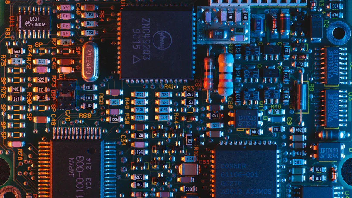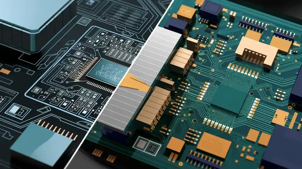
When you design a gps pcb, you control how well your gps works. Good gps pcb design improves accuracy and keeps your device reliable. If you make mistakes, you may see problems like longer trace lengths, more noise, and even short circuits. These issues can hurt your gps performance. Common problems include:
Increased trace lengths that weaken signal integrity
Overlapping parts that create noise and heat
Small gaps between parts that cause shorts
Careful planning helps you avoid these problems and build a strong gps device.
關鍵要點
Proper antenna placement on the top layer of the PCB enhances GPS signal reception and accuracy.
Use impedance matching techniques to ensure smooth signal transfer from the antenna to the receiver, reducing signal loss.
Follow datasheet guidelines for layout to avoid common design mistakes and improve GPS performance.
Implement controlled impedance routing to maintain signal integrity and reduce electromagnetic interference.
Select high-quality materials and maintain tight manufacturing tolerances to ensure reliable GPS functionality.
GPS Antenna Placement

You play a key role in gps pcb design when you choose where to place the gps antenna. The antenna location affects gps accuracy and performance. You want your device to receive clear signals for reliable navigation. Careful placement helps you avoid interference and signal loss.
Top Layer Positioning
You should place the gps antenna on the top layer of the pcb. This position gives the antenna a clear path to receive signals from satellites. You avoid obstacles that block or weaken the signal. You keep the antenna away from noisy components like processors and power circuits. You also make sure there is enough space around the antenna. This space helps the antenna radiate energy and improves performance.
Tip: Place the gps antenna near the edge of the pcb. You reduce interference and boost signal strength.
Impedance Matching for Performance
Impedance matching helps you maximize power transfer and minimize signal reflection. You want the signal to travel smoothly from the antenna to the gps receiver. You can use matching networks such as L-networks, π-networks, or T-networks. These networks help you adjust the impedance between the antenna and the pcb traces. You also match the trace characteristic impedance to the system impedance. This step reduces signal loss and improves gps pcb design.
Use matching networks to connect the antenna and receiver.
Match trace impedance to system impedance.
Avoid sharp bends in traces to keep signal integrity.
You improve gps performance when you follow these steps. You keep the signal strong and clear for accurate navigation.
Layout Following Datasheet Guidelines
You should always follow the datasheet guidelines for gps antenna layout. The datasheet gives you important information about spacing, trace width, and ground connections. You avoid common mistakes by checking the datasheet before you design a gps pcb. You keep the antenna away from metal parts and large ground planes. You use recommended materials for the pcb to support gnss signals.
Note: The datasheet helps you choose the right layout for your gps pcb design. You get better accuracy and performance when you follow these instructions.
You build a strong foundation for gps devices when you focus on antenna placement. You avoid signal loss and interference. You help your device achieve reliable navigation and robust performance.
Layer Stackup in GPS PCB Design

Multi-Layer Configuration
You build a strong foundation for gps pcb design when you use a multi-layer stackup. Multiple layers help you manage signal paths and reduce interference. You improve gps performance and accuracy by separating high-speed traces from power and ground planes. You keep the gps antenna on the top layer for clear navigation signals. You can see a typical high-performance gps pcb stackup 在下表中:
層數 | 產品說明 |
|---|---|
1 | High-speed signal traces and components |
2 | 地平面 |
3 | Power plane (e.g., 3.3V) |
4 | Power plane (e.g., 5V) |
5 | 地平面 |
6 | Additional signal traces or low-speed I/O |
You use this structure to keep signals clean and reduce noise. You also make routing easier for complex gps circuits.
Ground and Power Plane Setup
You set up ground and power planes to protect sensitive gps signals. You place ground planes close to signal layers to shield them from interference. You use separate power planes for different voltages to prevent cross-talk. You keep the ground plane continuous under the gps antenna and signal traces. This step helps you maintain signal integrity and boost gps performance.
Tip: You avoid splitting ground planes. You keep them solid to support reliable navigation and gnss operation.
介電材料選擇
You choose the right dielectric material to minimize signal loss in your pcb. You select materials with a low dielectric constant for high-speed gps signals. You improve performance and reduce crosstalk between traces. You can see the advantages of these materials in the table below:
企業優勢 | 產品說明 |
|---|---|
High-speed signal propagation | Lower losses due to low dielectric constant |
Reduced crosstalk | Minimizes interference between traces and vias |
Limits capacitive coupling | Reduces circuit complexity and improves performance |
Mismatched trace lengths | Lowers adverse effects in parallel nets |
你來選 materials like Rogers 4350B, RT Duroid 5880, and Isola-I speed for gps pcb design. These materials help you achieve strong signal quality and reliable gps accuracy.
You build a gps pcb that supports robust navigation and gnss performance when you focus on layer stackup. You protect signals, reduce noise, and keep your device reliable.
Signal Integrity and RF Performance
You need to protect gps signals from noise and interference to achieve the best accuracy and performance. Good gps pcb design helps you keep signals clean and strong. You can use several techniques to improve signal integrity and support reliable navigation.
電磁幹擾與串擾抑制
Electromagnetic interference (EMI) and crosstalk can weaken gps signals and reduce accuracy. You can take these steps to reduce EMI and crosstalk in your pcb:
Place all external connections on one edge of the pcb. This setup helps you control noise and keeps signals organized.
Avoid routing high-speed traces near the edge. You maintain a good reference ground and prevent unwanted noise.
Mount the pcb on a metal chassis if you have high-speed circuits between connectors. This method shorts out induced voltage and protects your gps antenna.
Check for I/O traces near high-speed traces. You stop crosstalk before it starts.
Ground heatsinks with a low-impedance bond. This action reduces electric field coupling and keeps your gps signals clear.
You improve gps performance and make your device more reliable when you follow these steps.
Waveguide and Back-Drilling Techniques
You can use waveguide and back-drilling techniques to boost RF performance in your gps pcb. Back drilling removes unused parts of vias, which helps reduce signal reflection and delay. This method works best in multi-layer pcbs with high-frequency gps signals. For example, back drilling can decrease signal delay from 12ps/in to 5ps/in when signal frequencies go above 15GHz. You get faster and cleaner gps signals, which leads to better navigation and gnss accuracy. For single or double-layer boards, back drilling may not give you enough benefit for the cost.
Shielding and Decoupling
Shielding and decoupling protect your gps circuits from noise and interference. You can use these methods to keep your gps pcb design strong:
Use metal enclosures and ground planes to block outside noise.
Isolate critical circuits with pcb-level shields and conductive cans.
Prevent noise from spreading by using isolation techniques.
Choose feed-through or stand-off capacitors with low lead inductance for high-frequency filtering.
Use solid-state capacitors in circuits with high ripple or voltage changes.
These steps help you maintain signal quality and improve gps performance. You support reliable navigation and strong gnss operation by keeping noise away from your gps antenna.
Routing Strategies for GPS PCB
受控阻抗佈線
You improve gps pcb performance when you use controlled impedance routing. You keep signals clean and strong by following these best practices:
保持一個 constant reference plane under high-speed traces. This step helps the return path of the signal and avoids noise.
Avoid routing traces over split planes. The signal return path cannot follow the trace, which leads to EMI and weak gps performance.
Maintain proper trace width and spacing. Use the 3W rule, where the ground plane should be at least three times the trace width on each side.
Match trace lengths for differential pairs. You minimize propagation delay mismatches and keep gps signals accurate.
You support reliable navigation and strong gnss operation when you follow these steps.
Trace Length Optimization
You boost gps accuracy when you optimize trace lengths in your pcb. Short traces help signals travel faster and reduce errors. You keep signal integrity high, which improves timing and positioning accuracy for gps systems. You also make your device more reliable. You prevent unexpected failures in systems that depend on gps signals. You increase system efficiency because you reduce the need for signal re-transmission and lower errors.
Tip: Keep traces as short and direct as possible. You help your gps antenna deliver clear signals for precise navigation.
High-Density Signal Paths
You face challenges when you route high-density signal paths in your gps pcb. You can use these strategies to overcome them:
保持走線短 and straight. You reduce errors and reflections.
Route high-speed signals over a solid ground plane. You maintain signal integrity.
Increase spacing between traces. You minimize crosstalk.
Match trace lengths for differential pairs. You avoid skew and keep gps signals accurate.
Avoid routing high-speed signals near power sections. You prevent interference.
You build a pcb that supports strong gps performance and reliable navigation when you use these routing strategies.
Manufacturing for GPS PCB Performance
Material and Tolerance Choices
You need to select the right materials to achieve strong gps performance. The material you choose affects signal quality and reliability. Some materials work better for high-frequency gps applications. You can see the main options in 下表:
材料類型 | 關鍵屬性 | 最佳用例 |
|---|---|---|
高Tg FR-4 | High glass transition temperature, moderate dielectric constant | Consumer-grade automotive gps units |
PTFE-Based Laminates | Low dielectric constant, very low loss | High-frequency gps and radar systems |
Ceramic-Filled Materials | Low dielectric constant, high thermal conductivity | Aerospace and military navigation systems |
聚酰亞胺 | Excellent thermal stability, low expansion | Marine or space navigation systems |
You should also pay attention to manufacturing tolerances. Tight tolerances help you keep signal paths accurate. This step supports consistent gps pcb performance.
DFM and Testing
You improve your pcb production when you use design for manufacturability (DFM) best practices. Start DFM early in your design process. Check your design at each stage to avoid costly mistakes. Follow these tips:
Review your schematic, component placement, and routing for errors.
Keep enough space between drill holes and copper traces.
Use correct aspect ratios for holes and board thickness.
Run DFM analysis before final approval.
These steps help you reduce costs, improve reliability, and speed up your time to market. You also need to test your gps pcb before mass production. Important tests include:
通電測試
GNSS signal test
Antenna connection test
溫度循環測試
振動測試
Final function test
Outdoor and mobile devices need extra checks. Test for temperature changes, vibration, battery behavior, and wireless stability before large production.
質量保證
You must use strong quality assurance methods to keep your gps pcb reliable. Use both manual and automated inspections. The table below shows common quality checks:
測試方法 | 產品說明 |
|---|---|
線上測驗 (ICT) | Checks circuits for open or short circuits. |
飛針測試 | Finds loose connections without power. |
功能測試 | Confirms the pcb works as expected. |
自動化光學檢查 | Uses cameras to find missing parts or soldering problems. |
X射線檢查 | Looks inside the pcb for hidden shorts or openings. |
電氣測試 | Measures output signals to check performance. |
視力檢查 | Finds physical damage that could hurt performance. |
You should also track your components and assembly steps. This traceability helps you find and fix problems quickly. When you combine these steps with robust gnss integration, you get better positioning accuracy and stronger signal reliability. Your gps pcb will perform well even in tough environments.
You achieve optimal gps performance when you focus on antenna placement, signal integrity, and careful manufacturing. Follow datasheet guidelines to select materials that prevent corrosion and electrical issues. Use simulation and testing to validate your design. 最新進展, such as antenna integration and improved shielding, help you build reliable gps devices. Industry standards like ISO 9001 和 ISO 9100 ensure quality and precision. Keep improving your skills and pay attention to every detail for the best results.
標準版 | 目的 | Impact on GPS PCBs |
|---|---|---|
ISO 9001 | 質量管理體系 | Ensures reliability and precision |
ISO 9100 | 航空航太品質管理 | Maintains high standards |
常見問題
What is the most important factor for GPS PCB performance?
Antenna placement matters most. You should keep the antenna on the top layer and away from noisy parts. This step helps you get clear signals and better GPS accuracy.
How do you reduce noise in a GPS PCB?
您可以:
Use solid ground planes.
Keep traces short.
Add shielding around sensitive circuits.
These steps help you block interference and keep signals clean.
Which materials work best for high-frequency GPS PCBs?
材料 | 好處 |
|---|---|
PTFE Laminates | 低訊號損失 |
Ceramic-Filled | 高熱穩定性 |
高Tg FR-4 | 適用於大多數用途 |
You should pick materials based on your device’s needs.
Why should you follow datasheet guidelines?
You get the best results when you follow datasheet rules. These guides show you the right trace width, spacing, and layout. You avoid mistakes and improve GPS reliability.